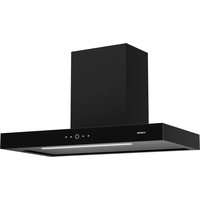
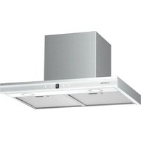
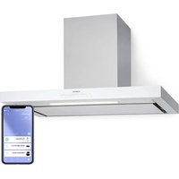
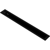
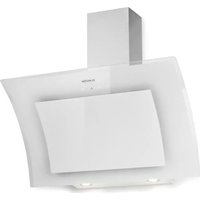
Futurelight Smart - Basket Klarstein - Free user manual and instructions
Find the device manual for free Futurelight Smart Klarstein in PDF.

User questions about Futurelight Smart Klarstein
0 question about this device. Answer the ones you know or ask your own.
Ask a new question about this device
Download the instructions for your Basket in PDF format for free! Find your manual Futurelight Smart - Klarstein and take your electronic device back in hand. On this page are published all the documents necessary for the use of your device. Futurelight Smart by Klarstein.
USER MANUAL Futurelight Smart Klarstein
text_image
COOKINGCO COOKINGCO KINGCOOKING KINGCOOKING COOKINGCO KINGCOOKING KINGCOOKING KINGCOOKING
KLARSTEIN
www.klarstein.com

text_image
QR code image containing encoded data, no visible human-readable textINHALTSVERZEICHNIS
Produktdatenblatt 4
natural_image
Technical line drawing of a device with top, front, and side views (no text or symbols)Member of Berlin Brands Group
Handwerkerstr. 11
15366 Dahlwitz-Hoppegarten
Deutschland
natural_image
Symbol of a trash bin crossed with a diagonal line, no text or numbers presentBerlin Brands Group UK Ltd
PO Box 1145
Oxford, OX1 9UW
United Kingdom
Congratulations on purchasing this device. Please read the following instructions carefully and follow them to prevent possible damages. We assume no liability for damage caused by disregard of the instructions and improper use. Scan the QR code to get access to the latest user manual and more product information.

text_image
QR code image containing encoded data, no visible human-readable textCONTENTS
Product Data Sheet 28
Safety Instructions 30
Device Overview and Individual Parts 32
Installation 33
Operation 41
Device Control by Smartphone 42
Cleaning and Maintenance 43
Troubleshooting 47
Disposal Considerations 48
Declaration of Conformity 48
TECHNICAL DATA
| Item number 10038708, 10038709, 10038710 | |
| Power supply 220-240 V ~ 50 Hz | |
| WiFi standard 802.11 b/g/n | |
| WiFi frequency 2.4 GHz | |
| WiFi radio-frequency power (max.) 20 dBm | |
| Note: You can purchase an activated carbon filter separately for this cooker hood under item number 10035387. Please visit our website: www.hifi-tower.co.uk | |
PRODUCT DATA SHEET
Information according to Regulation (EU) No. 65/2014
Measurement and calculation methods according to EN 61591:1997+A1:2006+A2:2011+A11:2014+A12:2015
| Item number 10038708, 10038709, | 10038710 | ||
| Description Symbol Value Unit | |||
| Annual Energy Consumption AEC | hood | 60.6 kWh/Year | |
| Energy Efficiency class C | |||
| Fluid Dynamic Efficiency FDE | hood | 16.1 | |
| Fluid Dynamic Efficiency class D | |||
| Lighting Efficiency LE | hood | 9.4 Lux/W | |
| Lighting Efficiency class A | |||
| Grease Filtering Efficiency GFE | hood | 63.2 % | |
| Grease Filtering Efficiency class E | |||
| Air flow at minimum and maximum speed in normal use, intensive or boost excluded | 226.7/402.0 m3/h | ||
| Air flow at intensive or boost setting | - | ||
| Airborne acoustical A-weighted sound power emissions at minimum and maximum speed available in normal use | 48/62 | dB | |
| Airborne acoustical A-weighted sound power emissions at intensive or boost setting | - | dB | |
| Power consumption in off mode | P_o | - | W |
| Power consumption in standby mode | P_s | 1.68 (WIFI is connected, according to EU801/2013, it is within 2W) | W |
| Contact details | Chal-Tec GmbH, Wallstraße 16, 10179, Berlin, Germany | ||
Information according to Regulation (EU) No. 66/2014
Measurement and calculation methods according to EN 61591:1997+A1:2006+A2:2011+A11:2014+A12:2015
| Item number 10038708, 10038709, | 10038710 | ||
| Description Symbol Value Unit | |||
| Annual Energy Consumption AEC | hood | 60.6 kWh/Year | |
| Time increase factor f 1.4 | |||
| Fluid Dynamic Efficiency FDE | hood | 16.1 | |
| Energy Efficiency Index EEI | hood | 78.0 | |
| Measured air flow rate at best efficiency point | QBEP | 205.8 m3/h | |
| Measured air pressure at best efficiency point | PBEP | 287 Pa | |
| Maximum air flow Q | max | 413.2 m3/h | |
| Measured electric power input at best efficiency point | WBEP | 101.7 W | |
| Nominal power of the lighting system | WL | 11.8 W | |
| Average illumination of the lighting system on the cooking surface | Emiddle | 111 | |
| Measured power consumption in standby mode | Po | 1.68 (WIFI is connected, according to EU801/2013, it is within 2W) | W |
| Measured power consumption off mode | Ps | - | W |
| Sound power level L | WA | 62 dB | |
| Contact details Chal-Tec GmbH, Wallstraße 16, 10179, Berlin, Germany | |||
SAFETY INSTRUCTIONS
- Read all instructions carefully before use and keep the user manual in a safe place for future reference.
- The installation work may only be carried out by an electrician or a qualified person. Before using the cooker hood, make sure that the voltage (V) and frequency (Hz) indicated on the cooker hood correspond to the voltage and frequency of the power supply in your household.
- We accept no liability for damage caused by improper use or installation.
• Children under 8 years of age must not use the cooker hood. - The appliance is intended for use in the home and similar environments only. It is not intended for commercial use.
- Clean the appliance and the filter regularly to keep the appliance working efficiently.
• Always disconnect the power plug from the socket before cleaning. - Clean the appliance exactly as indicated in the operating instructions.
- Do not use an open fire under the extractor hood.
- If the unit is not functioning normally, contact the manufacturer or a specialist company.
• Children from the age of 8 years and mentally, sensory and physically impaired persons may only use the device if they have been informed in detail about the functions and safety precautions by a supervisor responsible for them beforehand and understand the associated risks. - If the power cord is damaged, it must be replaced by the manufacturer, an authorised specialist company or a similarly qualified person.
- If the cooker hood is used with cookers that burn gas or other fuels, there must be adequate ventilation in the room.
- Do not flambé under the extractor hood.
- Caution: The surface of the unit may become hot during operation.
Important instructions for installation
- The air must not be discharged into a flue used for extracting flue gases from gas or other fuels (does not apply to appliances that only return the air to the room).
- Observe all regional regulations for the installation of ventilation systems.
Important notes on exhaust air operation
WARNING
Danger of poisoning from recirculated exhaust gases! Do not operate the appliance in extract air mode if it is operated together with a room air-dependent fi replace and sufficient air circulation is not guaranteed.
Room air-dependent fi replaces such as gas, oil, wood or coal heaters, boilers or instantaneous water heaters draw the air from the room and lead it outdoors through an exhaust pipe or chimney. In extract air mode, air is extracted from the kitchen and neighbouring rooms. Without sufficient supply air, negative pressure is created. Toxic gases from the chimney or exhaust pipe can be sucked back into the living rooms.
- Make sure that sufficient fresh air supply is guaranteed and that the air can circulate.
- A supply air/exhaust air wall box is not sufficient to ensure compliance with the limit value.
Safe operation is only possible if the negative pressure at the location of the fi replace does not exceed 4 Pa (0.04 mbar). This can be achieved if the air required for combustion can flow in through non-closable openings in doors and windows in conjunction with a supply air / exhaust air wall box. In any case, have a master chimney sweep advise you and assess the entire ventilation system of the house. If necessary, they can tell you the necessary measure for ventilation.
If the cooker hood is used exclusively in recirculation mode, operation is possible without restriction.
Important note on dismantling the unit
- Disassembly is the same as installation/assembly in reverse order.
- Have a second person help you during disassembly to avoid injury.
DEVICE OVERVIEW AND INDIVIDUAL PARTS
| 1 Ceiling mount | |
| 2 Wiring plate | |
| 3 Decorative panel | |
| 4 Wire ropes | |
| 5 Housing | |
| 6 Activated carbon filter | |
| 7 Grease filter | |
| For installation you will also need: • Fixings to secure the unit housing and anti-tilt brackets • Fixations for attaching the mounting brackets |
INSTALLATION
Before installation
- Remove all the protective film and take out the filters before installing the cooker hood.
Location
- The extractor hood must be fitted to the ceiling. Keep a minimum distance of 60 cm from electric hobs and 65 cm from gas burners.
Dimensions:
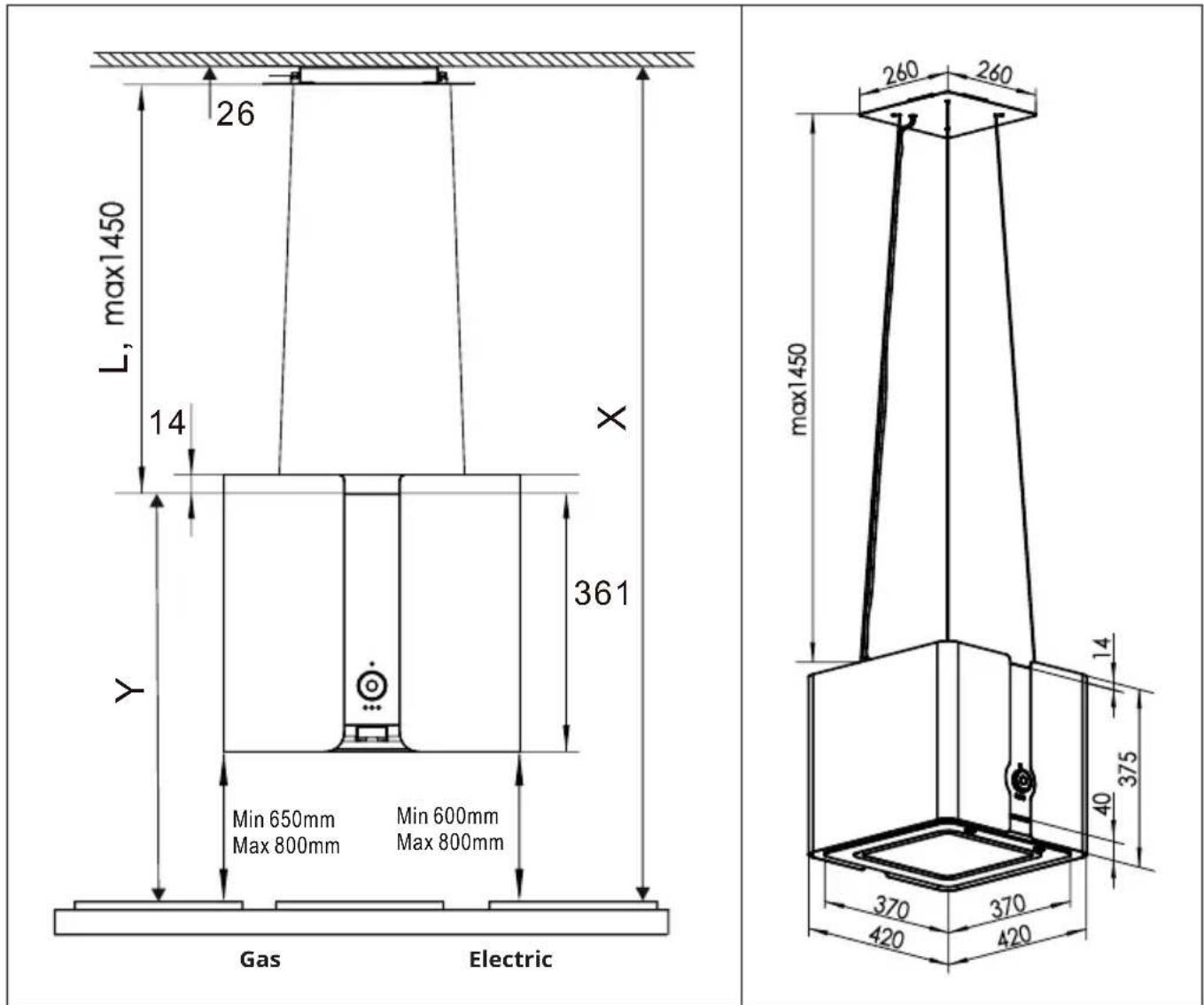
text_image
26 L, max1450 14 X 361 Y Min 650mm Min 600mm Max 800mm Max 800mm Gas Electric max1450 260 260 14 375 40 370 370 420 420Minimum distances (between cooker hood and top of cooker)
| Cooker type Minimum distance | distance Maximum distance | |
| Gas 650 mm 800 mm | ||
| Electric 600 mm 800 mm |
Note: If a larger minimum distance for cooker hoods is specified in the operating instructions of the cooker, this minimum distance and not the one mentioned above must be observed.
Installation on the ceiling
Follow the direction shown in figure 6 to hold the mounting brackets to the ceiling. Mark the location of the 4 holes on the ceiling where the cooker hood is to be positioned.
| 1 | |
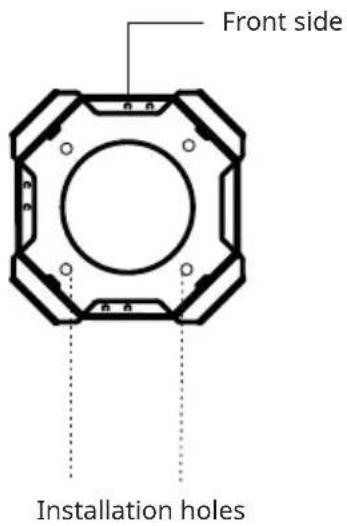 | Hold the mounting bracket the right way up (as shown in the illustration) on the ceiling and mark 4 holes where the hood is to be fitted. |
| 2 | |
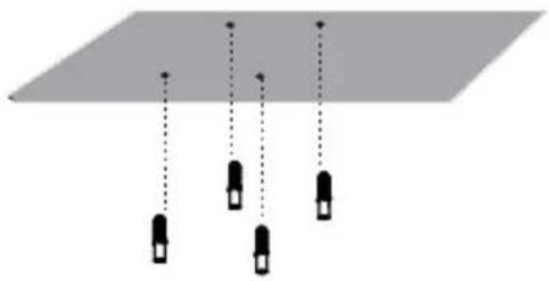 | Drill 4 holes with a diameter of 10 mm into the ceiling and then insert the dowels into the holes. |
| 3 | |
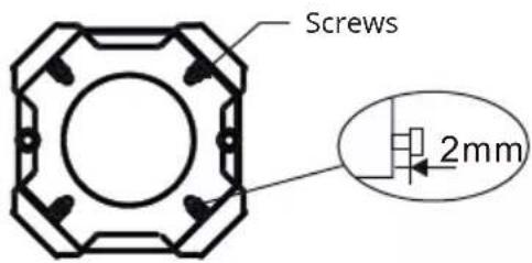 | Adjust the 4 screws on the bracket so that they protrude 2 mm. |
| 4 | |
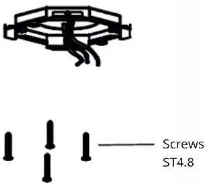 | Pull the power cable through the hole in the bracket and fi x the bracket with four screws ST4.8. |
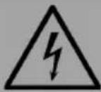
WARNING
Electrocution hazard! Failure to install the screws or bracket in accordance with these instructions may result in electrical hazards.
| 5 | |
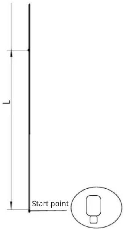 | Measure the length of the wire ropes (L) and refer to the dimension given under 'Dimensions': L = X-Y-26 (mm). Mark a line on the wire ropes.Note:The extractor hood should be installed at a height of 65-80 cm (gas) or 60-80 cm (electric cooker) above the starting point of the hob. If a larger minimum distance for cooker hoods is specified in the operating instructions of the cooker, this minimum distance and not the one mentioned above must be observed. |
| 6 | |
 |  |
| Wire | |
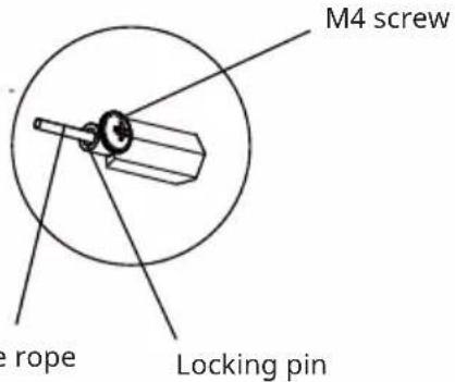
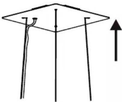
| Pass the wire ropes through the screws on the bracket. Adjust the length of the ropes to the marking line and fix them with the securing pins. | |
| 7 | |
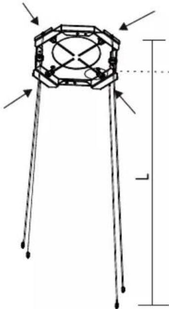
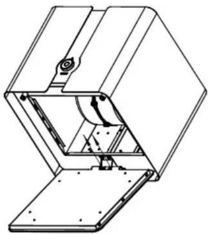
| Guide the 4 wire ropes through the holes in the decorative panel and attach them to the mounting bracket with 2 magnets. Note: The opening for the power cable in the decorative panel must be positioned as shown in the illustration. | |
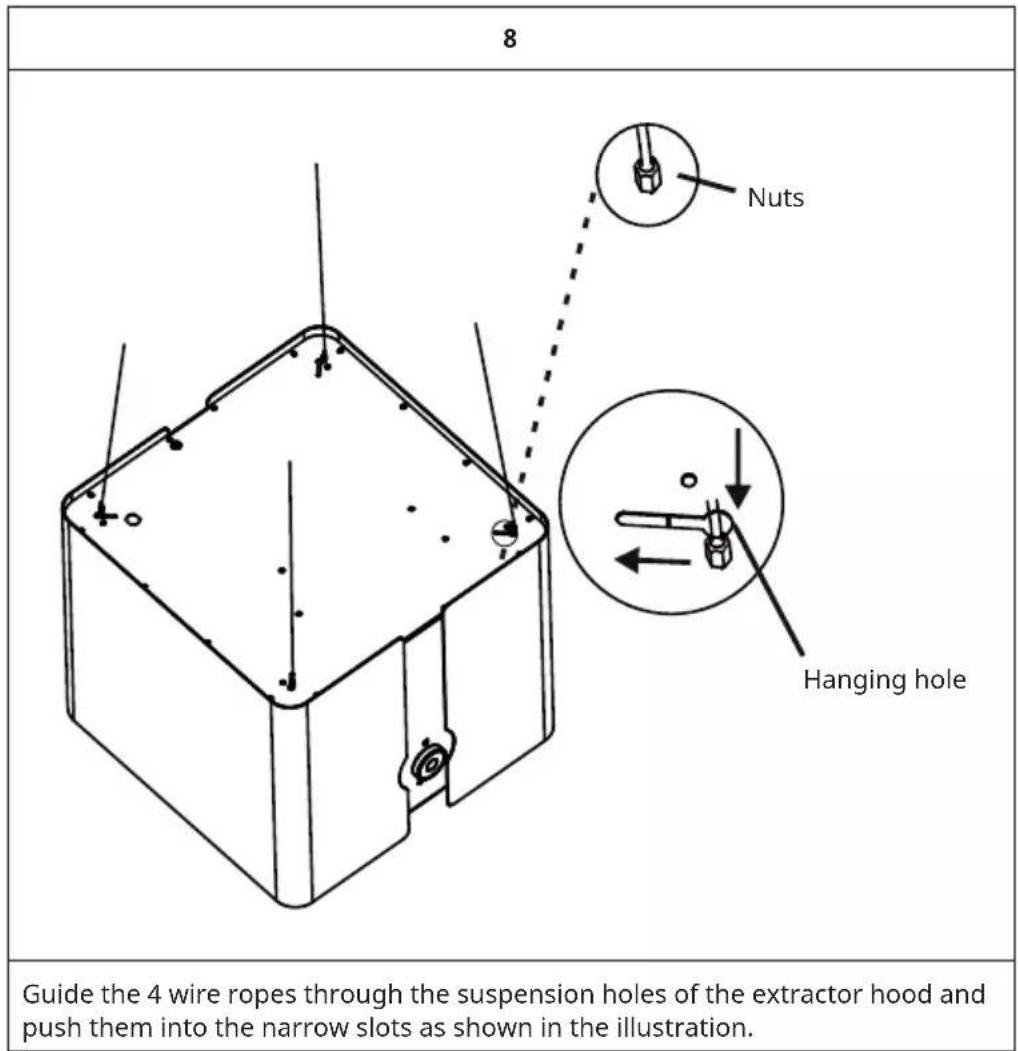
text_image
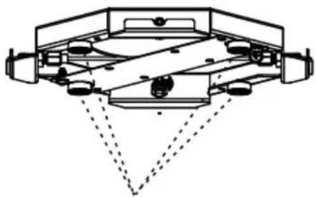
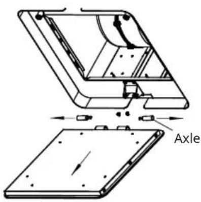
8 Nuts Hanging hole Guide the 4 wire ropes through the suspension holes of the extractor hood and push them into the narrow slots as shown in the illustration.9
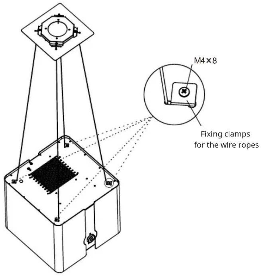
text_image
M4×8 Fixing clamps for the wire ropesFasten the wire ropes with screws to the 4 small fastening clips.
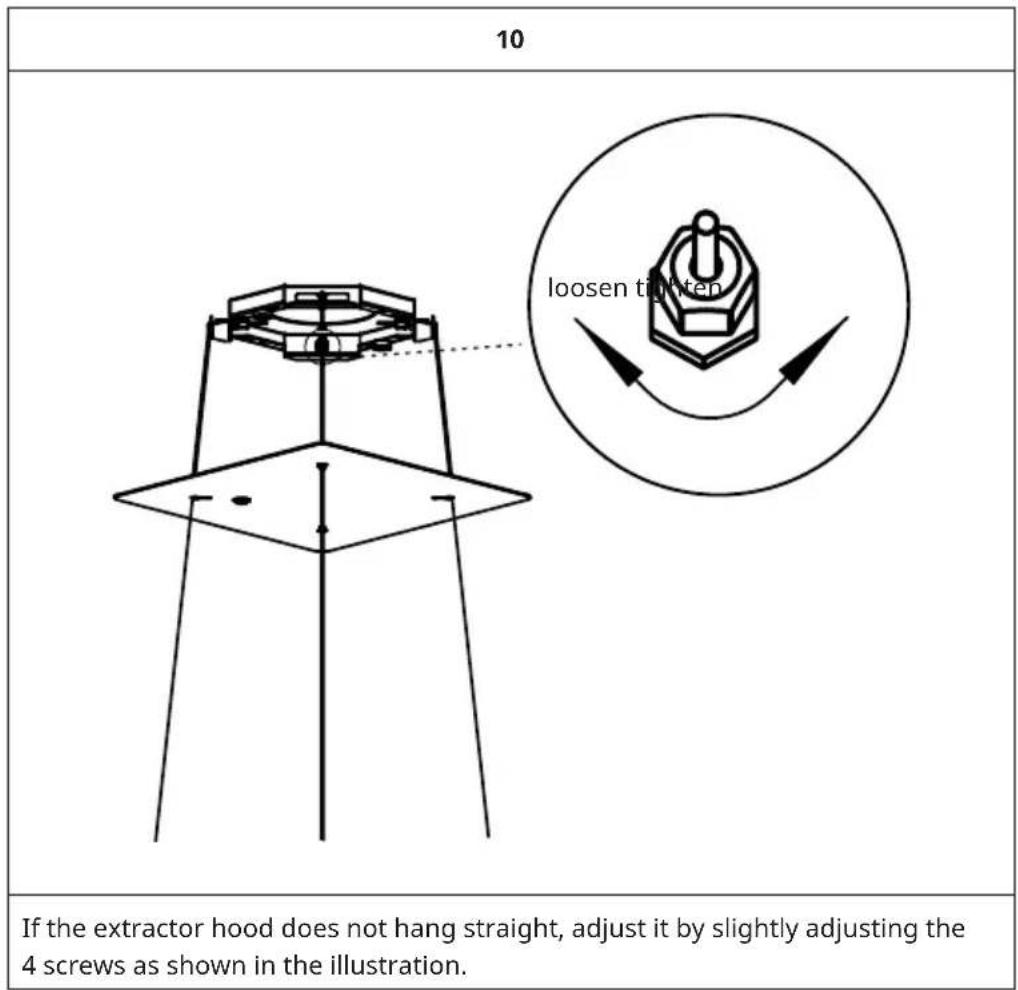
text_image
10 If the extractor hood does not hang straight, adjust it by slightly adjusting the 4 screws as shown in the illustration.| 11 | |
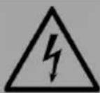
| Wire the cables according to the marking of the wires (L, N & earth). Note: This installation step MUST be carried out by a qualified electrician! | |
| WARNING Electrocution hazard! This unit is a protection class I unit. This unit must be earthed. | |
| 12 | |
 |  |
| Magnets | |
| Stow all the wiring in the mounting bracket. Then attach the other two magnets to the bracket. A total of 4 magnets are required to securely fasten the decorative panel. | |
| 11 | |
 | Finally, slide the decorative panel up to the mounting bracket. |
OPERATION
- The best results can be achieved if you use the appliance on a low setting in normal conditions and on a high setting for concentrated odours.
- Switch on the cooker hood for a few minutes before you start cooking.
- The cooker hood should be left on for at least 5 minutes after cooking until all odours have dissipated.
- The control panel is located on the front of the unit.
Control panel
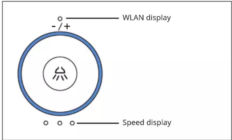
text_image
- /+ WLAN display Speed displaySwitching the light on and off
Press the light button ⌘ to switch on the light at a low brightness level. Press the light button ⌘ again to increase the brightness. If you press the light button ⌘ again, the light is switched off.
Switching the fan on and off
Turn the control dial clockwise to increase the fan speed. Turn the control dial counter-clockwise to decrease the fan speed. The speed levels can be set as follows: 0-1-2-3-2-1-0.
Control via hand movement sensor
The cooker hood has a hand movement sensor located on the light. Move your hand to the right to increase the fan speed. Move your hand to the left to decrease the fan speed. The speed levels can be set as follows: 0-1-2-3-2-1-0.
DEVICE CONTROL BY SMARTPHONE
If you integrate the device into your home WiFi, you can conveniently operate it via the associated Klarstein app. The app not only allows you to remotely control the device via your smartphone, but also gives you access to recipes and additional information.
Follow these steps to connect your smartphone to your Klarstein device:
- Download the Klarstein app first by scanning the QR code with your smartphone (see below), or download it directly from App Store or Google Play.
- Make sure your smartphone is connected to the same WiFi network that your Klarstein device is to be connected to.
- Open the Klarstein app.
- Sign in to your account. If you do not have an account, sign up in the Klarstein app.
- Follow the instructions from the app.
App Download
Use the scan function of your smartphone to scan the QR code and save the app on your smartphone.
Note: The app provides further information on how to use the app and help on how to connect to your device as soon as you open it for the first time.
| iOS Android | |
 |  |
Troubleshooting connection problems
If your Klarstein device cannot be found in the WLAN, check the following:
• Is the device plugged in?
- Is the WiFi feature of my phone enabled?
- Is the WiFi function of the Klarstein device activated? (Follow the instructions in the app)
- Has the WLAN password been entered correctly?
- Are the router, Klarstein device and smartphone in the immediate vicinity during the connection attempt? (Ideally no more than 5 m apart)
- If you have deactivated the 2.4 GHz band in the settings of your wireless router, activate it in your router settings.
Note: For further help, follow the instructions in the app when setting up the connection.
CLEANING AND MAINTENANCE
Cleaning instructions
Note: The outer surfaces are very sensitive. Take extreme care when cleaning to avoid scratches and abrasions. Follow the cleaning instructions to achieve the best results without damaging the cooker hood.
- Switch off the extractor hood and pull the plug out of the socket before cleaning and maintenance.
- Clean the outer surfaces of the cooker hood with a damp cloth and a solution of water and mild detergent. Do not use abrasive cleaners. Use a soft cloth for cleaning to avoid scratches. If the outer surfaces are still damp after cleaning, rub them with a dry cloth.
- Never use corrosive, abrasive or flammable cleaning agents or products containing bleach.
- Never insert sharp objects into the protective cover of the motor.
- Always clean the control panel and filter cover with a damp cloth and mild detergent only.
- It is extremely important to clean the appliance regularly and replace the filters at the recommended intervals. Failure to observe this will result in grease deposits which can cause a fire.
- Clean the appliance regularly after use to remove all residues from cooking, especially residues from acidic fruits, yoghurt and milk-based products.
Removing the grease filter
natural_image
Technical line drawing of a device with top, front, and side views (no text or symbols)Open the light panel, push the grease filter upwards and then pull it out downwards.
Cleaning the grease filters
Note: The metal grease filters must be removed and cleaned at least every 4 weeks, either by hand or in the dishwasher.
- Hand wash: Soak the grease filters in hot water with a grease solvent for about one hour. Then rinse the grease filters thoroughly with hot water. Repeat this step if necessary. Replace the grease filters only when they are completely dry.
- Dishwasher: Place the grease filters in the dishwasher. Select the strongest cleaning programme with the highest temperature (at least 65 °C). Repeat the procedure. Replace the grease filters only when they are completely dry. If you clean the grease filters in the dishwasher, slight discolouration may occur on the filters. This has no influence on the filter performance.
Cleaning the inner casing
WARNING
Electrocution hazard! Switch off the unit before cleaning the inner casing.
- Clean the inner casing with warm water and a grease cleaner (never use aggressive cleaning agents, scouring powder or steel brushes).
Replacing the LED lighting
- If one of the lights is defective, the entire lighting must be replaced.
- Do not replace the lighting yourself. This should only be done by a qualified professional. Contact the customer service if you would like to have the LED lighting replaced.
WARNING
Electrocution hazard! Make sure that the unit is switched off before carrying out any maintenance work.
| 1 | 2 |
 |  |
| Open the light panel and remove the fi Iters (as shown in the illustration for removing the grease fi Iters). Disconnect all cable connections that are connected to the LED lighting. Then loosen the two screws as shown in the illustration. | Loosen the two axles. |
| 3 | 4 |
 |  |
| Loosen the 8 screws. Insert the new LED lighting. | |
Replacing the activated carbon filter
- The activated carbon filter should only be used if you want to use the unit in recirculation mode.
- The activated carbon filter cannot be cleaned or reprocessed and should generally be changed every 4 months.
Inserting the activated carbon filter
natural_image
Diagram of a mechanical assembly showing a wheel assembly and a motor drive system (no text or labels)Mount one activated carbon filter on the left and one on the right side so that the plastic grids protecting the fan wheel are covered, as shown in the illustration.
Note: Always state the model and serial number when reordering activated carbon filters. This information can be found on the type plate on the inside of the unit.
TROUBLESHOOTING
| Problem Solution | |
| The appliance does not work. Make sure | that the plug of the cooker hood is inserted in the socket. |
| Check whether a fan speed has been selected. | |
| Poor suction. Make sure that the fan speed has been set according to the requirements. | |
| The unit switches off during operation. The emergency safety system was triggered. | |
Note: If you have followed all of the above instructions and still have difficulty using the appliance, contact customer service.
DISPOSAL CONSIDERATIONS
natural_image
Symbol of a trash bin crossed with a diagonal line, no text or numbers presentIf there is a legal regulation for the disposal of electrical and electronic devices in your country, this symbol on the product or on the packaging indicates that this product must not be disposed of with household waste. Instead, it must be taken to a collection point for the recycling of electrical and electronic equipment. By disposing of it in accordance with the rules, you are protecting the environment and the health of your fellow human beings from negative consequences. For information about the recycling and disposal of this product, please contact your local authority or your household waste disposal service.
This product contains batteries. If there is a legal regulation for the disposal of batteries in your country, the batteries must not be disposed of with household waste. Find out about local regulations for disposing of batteries. By disposing of them in accordance with the rules, you are protecting the environment and the health of your fellow human beings from negative consequences.
DECLARATION OF CONFORMITY

text_image
CE UK CAManufacturer:
Chal-Tec GmbH, Wallstrasse 16, 10179 Berlin, Germany.
Importer for Great Britain:
Berlin Brands Group UK Ltd
PO Box 1145
Oxford, OX1 9UW
United Kingdom
Hereby, Chal-Tec GmbH declares that the radio equipment type Futurelight Smart is in compliance with Directive 2014/53/EU. The full text of the EU declaration of conformity is available at the following internet address: use.berlin/10038708
For Great Britain: Hereby, Chal-Tec GmbH declares that the radio equipment type Futurelight Smart is in compliance with the relevant statutory requirements. The full text of the declaration of conformity is available at the following internet address: use.berlin/10038708
Cher client, chère cliente,
text_image
QR code image containing encoded data, no visible human-readable textSOMMAIRE
natural_image
Simple line drawing of a mechanical or electrical component with no text, numbers, or symbolsnatural_image
Technical line drawing of a device with top, front, and side views (no text or symbols)natural_image
Symbol of a trash bin crossed with a diagonal line, representing no waste or discharge (no text or labels)DÉCLARATION DE CONFORMITÉ

text_image
CE UK CAFabricant :
Chal-Tec GmbH, Wallstraße 16, 10179 Berlin, Allemagne.
Berlin Brands Group UK Ltd
PO Box 1145
Oxford, OX1 9UW
United Kingdom
text_image
QR code image containing encoded data, no visible human-readable textÍNDICE
text_image
afl ojar arietarnatural_image
Simple line drawing of a mechanical or electrical component with no text, numbers, or symbolsnatural_image
Technical line drawing of a device with top, front, and side views (no text or symbols)natural_image
Diagram of a mechanical assembly showing a wheel assembly and a motor drive system (no text or labels)natural_image
Symbol of a trash bin crossed with a diagonal line, no text or numbers presentBerlin Brands Group UK Ltd
PO Box 1145
Oxford, OX1 9UW
United Kingdom
text_image
QR code image containing encoded data, no visible human-readable textINDICE
natural_image
Technical line drawing of a device with top, front, and side views (no text or symbols)natural_image
Symbol of a trash bin crossed with a diagonal line, no text or numbers presentBerlin Brands Group UK Ltd
PO Box 1145
Oxford, OX1 9UW
United Kingdom