
SmartEdge - Basket Klarstein - Free user manual and instructions
Find the device manual for free SmartEdge Klarstein in PDF.

| Product type | Range hood |
| Brand | Klarstein |
| Model | SmartEdge |
| Model numbers | 10046679, 10046680 |
| Energy efficiency class | A+ |
| Annual energy consumption | 15.1 kWh/year |
| Fluid dynamic efficiency | 30.4 (class A) |
| Lighting efficiency | 16.0 Lux/W (class D) |
| Grease filtering efficiency | 67.1% (class D) |
| Airflow (min) | 177 m³/h |
| Airflow (max) | 530 m³/h |
| Noise (min) | 34 dB |
| Noise (max) | 61 dB |
| Power supply | 220-240 V ~ 50/60 Hz |
| Number of speeds | 9 |
| Smartphone control | Yes, via Klarstein app |
| Delay shut-off timer | Yes, 1 minute |
| LED lighting | Yes |
| Minimum distance above hob | 65-75 cm |
| Grease filter | Metallic, machine washable |
| Activated carbon filter | Not washable, replace annually |
| Installation mode | Island |
| Extraction mode | Extraction or recirculation |
Frequently Asked Questions - SmartEdge Klarstein
User questions about SmartEdge Klarstein
0 question about this device. Answer the ones you know or ask your own.
Ask a new question about this device
Download the instructions for your Basket in PDF format for free! Find your manual SmartEdge - Klarstein and take your electronic device back in hand. On this page are published all the documents necessary for the use of your device. SmartEdge by Klarstein.
USER MANUAL SmartEdge Klarstein
area
| Category | Value | | -------- | ----- | | 1 | 100 | | 2 | 100 | | 3 | 100 | | 4 | 100 | | 5 | 100 | | 6 | 100 | | 7 | 100 | | 8 | 100 | | 9 | 100 | | 10 | 100 | | 11 | 100 | | 12 | 100 | | 13 | 100 | | 14 | 100 | | 15 | 100 | | 16 | 100 | | 17 | 100 | | 18 | 100 | | 19 | 100 | | 20 | 100 | | 21 | 100 | | 22 | 100 | | 23 | 100 | | 24 | 100 | | 25 | 100 | | 26 | 100 | | 27 | 100 | | 28 | 100 | | 29 | 100 | | 30 | 100 | | 31 | 100 | | 32 | 100 | | 33 | 100 | | 34 | 100 | | 35 | 100 | | 36 | 100 | | 37 | 100 | | 38 | 100 | | 39 | 100 | | 40 | 100 | | 41 | 100 | | 42 | 100 | | 43 | 100 | | 44 | 100 | | 45 | 100 | | 46 | 100 | | 47 | 100 | | 48 | 100 | | 49 | 100 | | 50 | 100 | | 51 | 100 | | 52 | 100 | | 53 | 100 | | 54 | 100 | | 55 | 100 | | 56 | 100 | | 57 | 100 | | 58 | 100 | | 59 | 100 | | 60 | 100 | | 61 | 100 | | 62 | 100 | | 63 | 100 | | 64 | 100 | | 65 | 100 | | 66 | 100 | | 67 | 100 | | 68 | 100 | | 69 | 100 | | 70 | 100 | | 71 | 100 | | 72 | 100 | | 73 | 100 | | 74 | 100 | | 75 | 100 | | 76 | 100 | | 77 | 100 | | 78 | 100 | | 79 | 100 | | 80 | 100 | | Note: The actual values are not provided in the code. I have used the label 'Value' as a placeholder for the value detection. You would need to run the code to get the actual values from the code list. Please note that the actual values would be the result of this example. You would need to run the code to get the actual values from the code list. You would need to run the code to get the actual values from the code list. You would need to run the code to get the actual values from the code list. You would need to run the code to get the actual values from the code list. You would need to run the code to get the actual values from the code list. You would need to run the code to get the actual values from the code list. You would need to run the code to get the actual values from you would need to run the code. You would need to run the code to get the actual values from you would need to run the code.INHALT
Technische Daten 3
natural_image
Line drawing of a hammer with a handle and base (no text or symbols)
natural_image
Line drawing of a handheld electric drill (no text or symbols)natural_image
Simple diagram of a rectangular box with three circular holes and a central icon (no text or symbols)Wasserwaage
INSTALLATION
natural_image
Hand inserting a plug into an electrical socket (no text or symbols visible)natural_image
Diagram showing a mechanical component before and after assembly, with dimension label A (no text or symbols present)natural_image
Technical diagram of a reinforced concrete column with embedded rebar and bolt holes, shown in two circular views (no text or labels)Hinweise
natural_image
Technical line drawing of a mechanical component with mounting holes and internal features, shown in two views (no text or symbols)natural_image
Technical line drawing of a vertical industrial platform with a magnified inset showing internal components (no text or symbols)natural_image
Isometric diagram of a vertical cylindrical structure with two downward arrows indicating force or displacement (no text or symbols)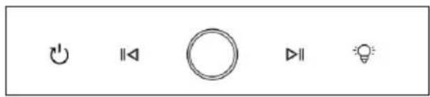
12345
natural_image
Diagram showing a circular fan with internal components and a recycling bin, illustrating the process of waste sorting (no text or symbols present)Austausch der Lampe
flowchart
graph LR
    A["Light bulb with light bulb"] --> B["No protection symbol"]
    B --> C["Thermal relay with 10° phase"]
    C --> D["Switch with 'RUSE' and 'OFF' buttons"]
natural_image
Symbol of a trash bin with crossed lines indicating no waste, and a solid black rectangle below (no text or labels)Name: Customer service Website:
Congratulations on purchasing this device. Please read the following instructions carefully and follow them to prevent possible damages. We assume no liability for damage caused by disregard of the instructions and improper use. Scan the QR code to get access to the latest user manual and more product information.

CONTENTS
Technical Data 21
Safety Instructions 22
Scope of Supply 24
Installation 25
Operation 29
Device Control by Smartphone 31
Cleaning and Maintenance 33
Troubleshooting 35
Notes on Environmental Protection 36
Disposal Considerations 36
Manufacturer & Importer (UK) 36
TECHNICAL DATA
Item number 10046679, 10046680
Power supply 220-240 V\~ 50-60 Hz
SAFETY INSTRUCTIONS
- Read all instructions carefully before use and keep this user manual in a safe place for future reference.
- The installation work may only be carried out by an electrician or a qualified person. Before using the cooker hood, make sure that the voltage (V) and frequency (Hz) indicated on the cooker hood correspond to the voltage and frequency of the power supply in your household.
• We accept no liability for damage caused by improper use or installation.
• Children under 8 years of age must not use the cooker hood. - The appliance is intended for use in the home and similar environments only. It is not intended for commercial use.
- Clean the appliance and the filter regularly to keep the appliance working efficiently.
• Always disconnect the power plug from the socket before cleaning. - Clean the appliance exactly as indicated in the operating instructions.
- Do not use an open fire under the extractor hood.
- If the unit is not functioning normally, contact the manufacturer or a specialist company.
• Children from the age of 8 years and mentally, sensory and physically impaired persons may only use the device if they have been informed in detail about the functions and safety precautions by a supervisor responsible for them beforehand and understand the associated risks. - If the power cord is damaged, it must be replaced by the manufacturer, an authorised specialist company or a similarly qualified person.
- If the cooker hood is used with cookers that burn gas or other fuels, there must be adequate ventilation in the room.
- Do not flambé under the extractor hood.
- Caution: The surface of the unit may become hot during operation.
Important instructions for installation
- The air must not be discharged into a flue used for extracting flue gases from gas or other fuels (does not apply to appliances that only return the air to the room).
- Observe all regional regulations for the installation of ventilation systems.
Important notes on exhaust air operation

WARNING
Danger of poisoning from recirculated exhaust gases! Do not operate the appliance in extract air mode if it is operated together with a room air-dependent fireplace and sufficient air circulation is not guaranteed.
Room air-dependent fireplaces such as gas, oil, wood or coal heaters, boilers or instantaneous water heaters draw the air from the room and lead it outdoors through an exhaust pipe or chimney. In extract air mode, air is extracted from the kitchen and neighbouring rooms. Without sufficient supply air, negative pressure is created. Toxic gases from the chimney or exhaust pipe can be sucked back into the living rooms.
- Make sure that sufficient fresh air supply is guaranteed and that the air can circulate.
- A supply air/exhaust air wall box is not sufficient to ensure compliance with the limit value.
Safe operation is only possible if the negative pressure at the location of the fireplace does not exceed 4 Pa (0.04 mbar). This can be achieved if the air required for combustion can flow in through non-closable openings in doors and windows in conjunction with a supply air / exhaust air wall box. In any case, have a professional chimney sweep advise you and assess the entire ventilation system of the house. If necessary, they can tell you the necessary measure for ventilation.
If the cooker hood is used exclusively in recirculation mode, operation is possible without restriction.
Important note on dismantling the unit
- Disassembly is the same as installation/assembly in reverse order.
- Have a second person help you during disassembly to avoid injury.
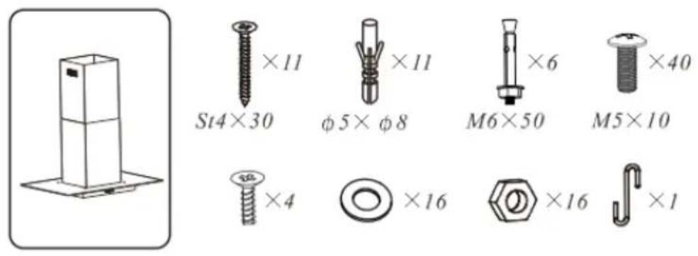
SCOPE OF SUPPLY
Scope of supply
Tools required
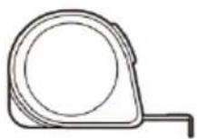
measuring tape
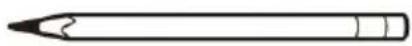
marker
screw driver hammer
natural_image
Line drawing of a hammer with a handle and base (no text or symbols)
natural_image
Line drawing of a handheld electric drill (no text or symbols)electric drill level
natural_image
Simple diagram of a rectangular box with three circular holes and a central icon (no text or symbols)INSTALLATION
Prepare for installation
flowchart
graph TD
    A["Top Roof"] --> B["Airflow Up"]
    B --> C{Return Flow}
    C -->|Yes| D["Downward Arrow to Top Roof"]
    C -->|No| E["Upward Arrow to Front Roof"]
    D --> F["Checkmark X"]
    E --> G["Checkmark X"]
    style A fill:#f9f,stroke:#333
    style B fill:#ccf,stroke:#333
    style C fill:#cfc,stroke:#333
    style D fill:#ffc,stroke:#333
    style E fill:#fcc,stroke:#333
    style F fill:#fff,stroke:#333
    style G fill:#fff,stroke:#333
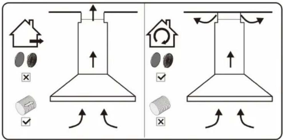
Ducted option Recirculation option
If you have an outlet to the outside, your cooker hood can be connected as above picture by means of an pipe (with an interior diameter of 150mm). If you do not have an outlet to the outside, you can go with recirculation mode by using carbon filter.
natural_image
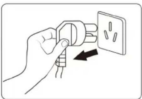
Hand holding a plug with an outlet, showing internal socket arrangement (no text or symbols)Before installation, turn the unit off and unplug it from the outlet.
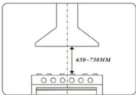
The cooker hood should be placed at a distance of 65-75 cm above the cooktop for the best effect.
Air outlet installation method
Place the T-shaped air outlet bracket underneath the inner chimney bracket and fix the T-shaped outlet on the T-shape outlet bracket with 2 screws.
natural_image
Diagram showing a mechanical component before and after assembly, with dimension label A (no text or symbols present)- Fix the pipe.
- Tighten up the screw from two side of chimney to fix the T-shape outlet after installing the chimney.
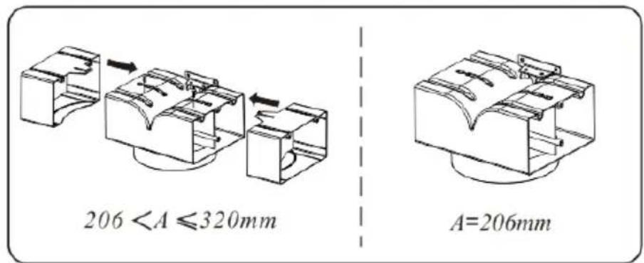
Choose suitable adjustment according to the size of chimney and fix the adjustment by the screws.
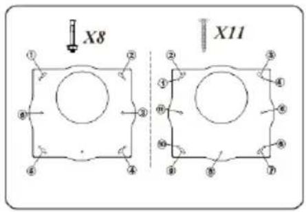
Island model installation
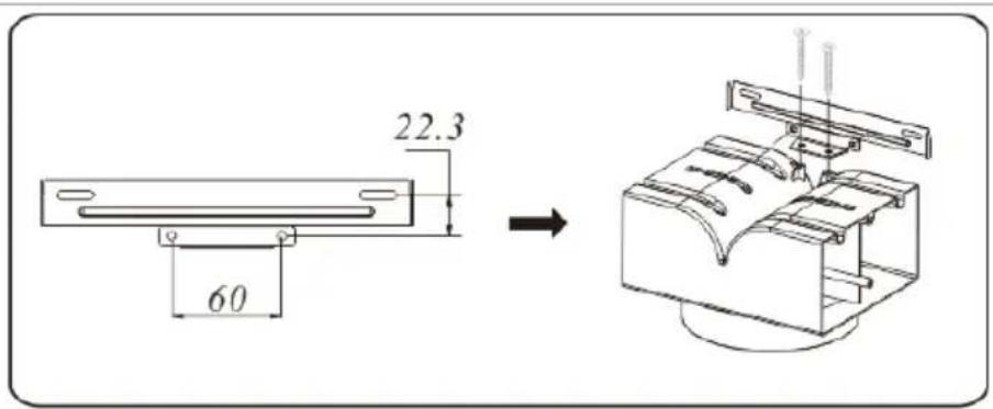
Position the hanging plate on the ceiling and then mark the position of the screw holes. The hanging plate should be securely fixed to the ceiling.
(1) 11×ST4 (30 mm) screws for wooden ceiling.
(2) 6×expansion bolts for cement ceiling.
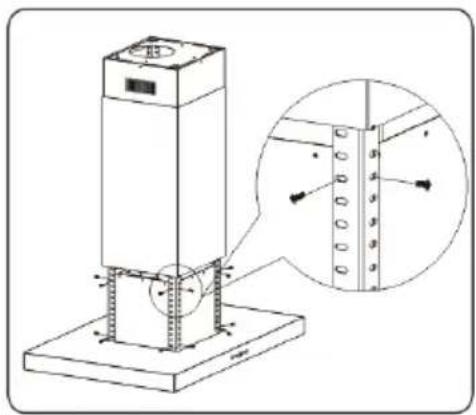
Fix 4 angle bars to the hanging plate, insert and tighten with 8 M5*10 screws.
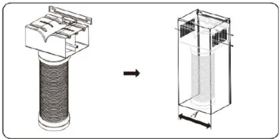
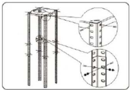
Put and extend the another 4 angle bars to the required height and fix them to the existing angle bars with 16 M5*10 screws and nuts and flat washers.
natural_image
Technical diagram of a reinforced concrete column with embedded rebar and bolt holes, shown in two circular views (no text or labels)Notes
• The angle bars must have an overlap of at least 100 mm.
- The above angle bars are outside to cover below angle bars.
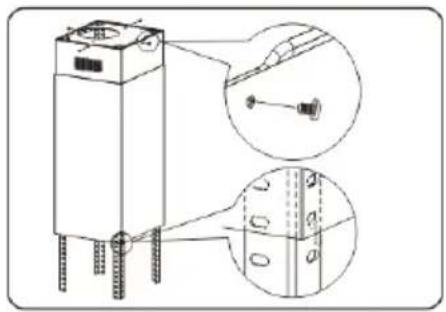
Tear off the film of chimneys and then put the inner chimney outside the angle bars and fix the inner chimney to the hanging plate with 4 ST4*6 screws. Then put the outer chimney outside the inner chimney and use the hood to catch it.
natural_image
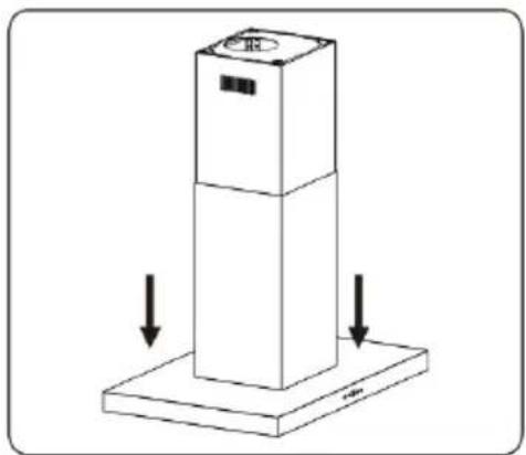
Technical line drawing of a mechanical device with mounting holes and internal components, shown in two views (no text or symbols)Put the body inside the angle bars and fix it to the each angle bar with 16 M5*10 screws.
Note: This stage of the installation process must be completed by two people.
natural_image
Technical line drawing of a vertical industrial platform with a magnified inset showing internal components (no text or symbols)Take away the hood and lay down the outer chimney, thus the installation is finished.
natural_image
Isometric diagram of a vertical cylindrical object with two downward arrows indicating force or movement (no text or symbols)OPERATION

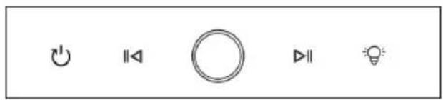
12345
1 Timer button
2 Decrease fan level button
3 ON/OFF button
4 Increase fan level button
5 Lighting button
Power on after plugged
All indicator lights turn on and emit a beep sound when plugged (with a beep sound every time the button is pressed). The button indicator lights and digital tubes are white, the display screen shows the number "8", lights up for 1 second and then turns off, entering the shutdown state.
ON/OFF button
To switch the cooker hood on: In the plugged standby state, short press the On/Off button. All indicator lights will light up at half brightness, the display screen will show "0", and enter standby mode. If there is no operation in this state for 2 minutes, it will return to off mode.
To switch the cooker hood off: In standby or power on mode, short press the On/Off button to turn off all functions and return to the off state.
Delayed shutdown: In the power on state, short press the Timer button to emit a beep sound, and the indicator light will flash white at a frequency of 1 second, entering the countdown to delayed shutdown (default is 1 minute and cannot be adjusted). At this time, the gear can also be switched, and after the countdown ends, all functions will be turned off and returned to the off state.
Lighting function
Short press the Lighting button. The indicator lights will all turn on, and the lighting will turn on. Short press the Lighting button again to turn off the indicator light and the lighting fixture (the lighting fixture is not controlled by the power button).
Fan power adjument
There are 9 fan speeds, which can be set by pressing the Inscrease/Decrease fan speed buttons.
Increase button: In standby mode, press the Increase button. The buzzer will sound once, the indicator light will be fully on for 2 seconds, and then enter a semi-lit state. The display screen will show "1", and the motor will start running in gear 1. Press the Increase button again, and the indicator light will be fully on for 2 seconds before entering a semi lit state. The motor gear will be increased by one gear (the highest gear is 9th gear), and the display screen will show the corresponding gear (without cycling).
Decrease button: In the power on state, press the Decrease button, the buzzer will sound once, and the indicator light will be fully on for 2 seconds before entering a semi-lit state. The motor gear will be decreased by one gear (the lowest gear is 0), and the display screen will show the motor gear. When the motor gear is set to "0", the motor stops running and returns to standby mode.
DEVICE CONTROL BY SMARTPHONE
If you integrate the device into your home WiFi, you can conveniently operate it via the associated Klarstein app. The app not only allows you to remotely control the device via your smartphone, but also gives you access to recipes and additional information.
Follow these steps to connect your smartphone to your Klarstein device:
- Download the Klarstein app first by scanning the QR code with your smartphone (see below), or download it directly from App Store or Google Play.
- Make sure your smartphone is connected to the same WiFi network that your Klarstein device is to be connected to.
- Open the Klarstein app.
- Sign in to your account. If you do not have an account, sign up in the Klarstein app.
- Follow the instructions from the app.
App Download
Use the scan function of your smartphone to scan the QR code and save the app on your smartphone.
Note: The app provides further information on how to use the app and help on how to connect to your device as soon as you open it for the first time.
| iOS Android | |
 |  |
Troubleshooting connection problems
If your Klarstein device cannot be found in the WLAN, check the following:
- The device is not plugged in. Make sure that your device is plugged into an electric socket.
- The device is not in pairing mode. Make sure that the WiFi indicator (LED) on the smart device control panel is blinking as described in the 'Reset WiFi settings' instruction of your smart device (instructions are usually available on device connection process).
- The WiFi access point does not operate on 2.4 GHz. Make sure that your access point operates on 2.4 GHz band and you have a separate SSID on 2.4 GHz band. If you are not sure about the operating band of your access point, please contact your internet provider company.
Important: please note that if your WiFi router is dual band - operating on both 2.4 GHz and 5 GHz band - you need to separate the SSIDs for each band and use the 2.4 GHz SSID for connection.
-
Firewall settings of your WiFi network; the firewall setting of your WiFi network may not allow the Klarstein app to configure the WiFi settings on your smart device. Please make sure that you are not using a public WiFi network, e.g. airports, dormitories, companies, etc.
-
Different credentials used in smartphone and the app. Make sure that the WiFi credentials entered in the Klarstein app are the same as the ones that your smartphone is connected to.
Following the above mentioned points, if your smart device still fails to connect to the app, please contact us via email for support: appsupport@go-bbg.com
CLEANING AND MAINTENANCE
Unplug the extractor hood before cleaning or servicing.
- Clean the surface of the hood regularly. Use mild soap or detergent to clean the hood.
- Do not use aggressive alkaline solutions or abrasive cleaners.
- Avoid using abrasive cleaners or dishwashing detergents.
- The grease filter can be washed out with mild soap or a mild detergent. (Heavy grease deposits may be difficult to remove and the filter may need to be replaced).
- The activated carbon filter cannot be cleaned and must be replaced regularly.
Note: The cleaning water must not penetrate into the electrical parts of the motor, control switch, etc.
Stainless steel
The stainless steel must be cleaned regularly (e.g.weekly) to ensure a long life expectancy.Dry with a clean soft cloth. A specialized stainlesssteel cleaning fluid may be used.
Control panel surface
The inlay control panel can be cleaned using warmsoapy water. Ensure the cloth is clean and well wrungbefore cleaning. Use a dry soft cloth to remove anyexcess moisture left after cleaning.
Active and active charcoal filter replacement
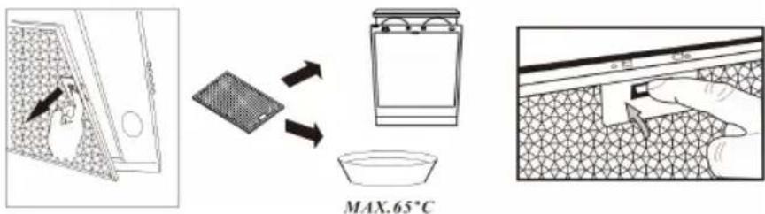
Grease mesh grease filters (monthly cleaning)
- The mesh filters can be cleaned by hand. Soak them for about 3 minutes in water with a mild detergent and then brush it gently with a soft brush. Do not apply too much pressure so as to avoid any damage to it. (Leave to dry naturally out of direct sun light)
- Filters should be washed separately to crockery and kitchen utensils. It is advisable not to use rinse aid.
- Remove the filter as shown in the following diagrams.
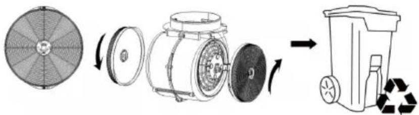
Activated charcoal filter (annual cleaning)
- Apply solely to unit that installed as a recirculation unit (not vented to the outside).
- This filter traps odours and must be replaced at least once a year depending on how frequent the cooker hood used.
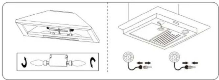
• Install the activated carbon filter on the housing and turn it in clockwise direction. Repeat the same on the other side but in clockwise direction.
natural_image
Diagram showing a circular fan blade, a cylindrical device with rotating parts, and a recycling bin (no text or symbols)Lamp replacement
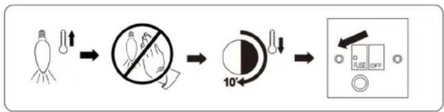
- Switch the unit off and unplug the appliance.
- Unscrew the incandescent bulb or disconnect the LED lamp wire and take out the lamp.
- Replace with the same type and rated bulb/LED lamp
The bulb may be hot, leave it 10 minutes before replacement.
flowchart
graph LR
    A["Light Bulb"] --> B["Light Bulb with Light Bulb"]
    B --> C["No Glare"]
    C --> D["10° Angle"]
    D --> E["Switch: O, R, S, F, G, H, I, J, K, L, M, N, O, P, Q, R, S, T, U, V, W, X, Y, Z"]
TROUBLESHOOTING
| Fault Possible Cause Solution | ||
| Light on, but motor does not work. | Fan switch turned off. Select a fan switch position. | |
| Fan switch failed. Contact service centre. | ||
| Motor failed Contact service centre. | ||
| Both light and fan do not work. | House fuses blown Reset/Replace fuses. | |
| Mains power cable is loose or disconnected | Refit mains power cable to power outlet. | |
| Oil leakage. One way valve | and the outlet are not tightly sealed | Take down the one way valve and seal with sealant. |
| Leakage from the connection of chimney and cover | Take chimney down and seal. | |
| Insufficient suction The distance between the cooker hood and the gas top is too far. | Refit the cooker hood to the correct distance. | |
| The suction power is insufficient. | The distance between the cooker hood and the gas top is too far | Refit the cooker hood to the correct distance. |
Notes:
Any electrical repairs to this appliance must conform to your local, state and federal laws. Please contact the service centre if in any doubt before undertaking any of the above. Always disconnect the unit from the power source when opening the unit.
NOTES ON ENVIRONMENTAL PROTECTION
- During cooking, make sure that there is sufficient air supply so that the cooker hood can operate efficiently and with low operating noise.
- Adjust the fan speed to the amount of steam produced during cooking. Use the intensive mode only when necessary. The lower the fan speed, the less energy is consumed.
- If large amounts of steam are produced during cooking, select a higher fan speed in good time. If the cooking steam has already dispersed in the kitchen, the cooker hood must be operated longer.
- Switch off the cooker hood when you no longer need it.
- Switch off the lighting when you no longer need it.
- Clean the filter at regular intervals and replace it if necessary to increase the effectiveness of the ventilation system and prevent fire hazards.
- Always put the lid on when cooking to reduce cooking steam and condensation.
DISPOSAL CONSIDERATIONS
natural_image
Symbol of a trash bin with crossed lines indicating no waste, and a solid rectangle below (no text or labels)If there is a legal regulation for the disposal of electrical and electronic devices in your country, this symbol on the product or on the packaging indicates that this product must not be disposed of with household waste. Instead, it must be taken to a collection point for the recycling of electrical and electronic equipment. By disposing of it in accordance with the rules, you are protecting the environment and the health of your fellow human beings from negative consequences. For information about the recycling and disposal of this product, please contact your local authority or your household waste disposal service.
MANUFACTURER & IMPORTER (UK)
Manufacturer:
Chal-Tec GmbH, Wallstrasse 16, 10179 Berlin, Germany.
Importer for Great Britain:
Berlin Brands Group UK Limited
PO Box 42
272 Kensington High Street
London, W8 6ND
United Kingdom
Nom: Customer service
Site web: https://www.elektronik-star.de/lnfo/Impressum/
Courriel: info@electronic-star.de
Téléphone: +49303001385500
Adresse:
Wallstraße 16
10179 berlin
Allemagne
Chère cliente, cher client,
SOMMAIRE
Fiche technique 39
natural_image
Line drawing of a hammer with a handle and base (no text or symbols)
natural_image
Line drawing of a handheld electric drill (no text or symbols)Perceuse électrique

natural_image
Simple diagram of a rectangular box with three circular holes and a central icon (no text or symbols)Niveau
INSTALLATION
natural_image
Hand holding a plug with a socket, showing an electrical switch (no text or symbols present)natural_image
Technical illustration of a mechanical component before and after assembly, showing internal structure and dimension label A (no text or symbols present)natural_image
Technical diagram of a reinforced concrete column with rebar and bolt holes, showing cross-sectional views (no text or labels)Remarques
natural_image
Technical line drawing of a mechanical component with two views (top and side), no visible text or symbolsnatural_image
Technical line drawing of a vertical industrial platform with a magnified inset showing internal components (no text or symbols)natural_image
Isometric diagram of a vertical cylindrical object with two downward arrows indicating force or movement (no text or symbols)FONCTIONNEMENT
12345
natural_image
Diagram showing a circular fan blade, a cylindrical device with rotating parts, and a recycling bin (no text or symbols)natural_image
Symbol of a trash bin with crossed lines indicating no waste, and a solid rectangle below (no text or labels)Nom: Customer service
Site web: https://www.elektronik-star.de/lnfo/Impressum/
Courriel: info@electronic-star.de
Téléphone: +49303001385500
Adresse:
Wallstraße 16
10179 berlin
Allemagne
Gentile cliente,
INDICE
Dati tecnici 57
natural_image
Line drawing of a hammer with a handle and base (no text or symbols)
natural_image
Line drawing of a handheld electric drill (no text or symbols)natural_image
Simple diagram of a rectangular box with three circular holes and a central icon (no text or symbols)INSTALLAZIONE
natural_image
Hand holding a plug with an outlet, showing internal socket arrangement (no text or symbols)natural_image
Diagram showing a mechanical component before and after assembly, with dimension label A (no text or symbols present)natural_image
Technical diagram of a reinforced concrete column with rebar and bolt holes, showing cross-sectional views (no text or labels)Note
natural_image
Technical line drawing of a cylindrical electronic component with mounting holes and internal wiring, shown with two magnified views (no text or symbols)natural_image
Technical line drawing of a vertical industrial platform with a magnified inset showing internal components (no text or symbols)natural_image
Isometric diagram of a vertical cylindrical object with two downward arrows indicating force or movement (no text or symbols)
12345
natural_image
Diagram showing a circular fan blade, a cylindrical device with rotating parts, and a recycling bin (no text or symbols)flowchart
graph LR
    A["Light bulb with light bulb"] --> B["No-dissipation symbol"]
    B --> C["10° angle adjustment"]
    C --> D["Switch state selection: O, R, S, OFF"]
natural_image
Symbol of a trash bin crossed with a diagonal line, representing waste sorting or restriction (no text or labels)
Nome: Customer service
Sito web: https://www.elektronik-star.de/lnfo/Impressum/
E-mail: info@electronic-star.de
ÍNDICE
Datos técnicos 75
natural_image
Line drawing of a hammer with a handle and base (no text or symbols)
natural_image
Line drawing of a handheld electric drill (no text or symbols)natural_image
Simple diagram with three circles and a central rectangular block (no text or symbols)INSTALACIÓN
natural_image
Hand inserting a plug into an electrical socket (no text or symbols visible)natural_image
Diagram showing a mechanical component before and after assembly, with dimension label A (no text or symbols present)natural_image
Technical diagram of a reinforced concrete column with rebar and bolt holes, showing cross-sectional views (no text or labels)Notas
natural_image
Technical line drawing of a mechanical device with mounting holes and internal components, shown in two views (no text or symbols)natural_image
Technical line drawing of a vertical industrial platform with a magnified inset showing internal components (no text or symbols)natural_image
Diagram of a vertical cylindrical device with two downward arrows indicating force or movement (no text or symbols present)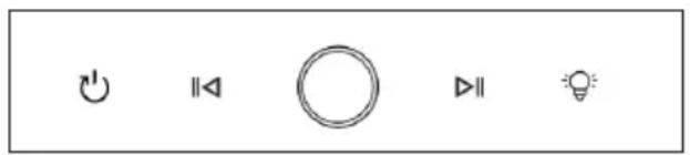
12345
natural_image
Diagram showing a circular fan blade, a cylindrical device with rotating parts, and a recycling bin (no text or symbols)natural_image
Symbol of a trash bin with crossed lines indicating no waste, and a solid rectangle below (no text or labels)
- INHALT
- INSTALLATION
- Hinweise
- Austausch der Lampe
- CONTENTS
- TECHNICAL DATA
- SAFETY INSTRUCTIONS
- Important instructions for installation
- Important notes on exhaust air operation
- WARNING
- Important note on dismantling the unit
- SCOPE OF SUPPLY
- Air outlet installation method
- Island model installation
- Notes
- OPERATION
- Power on after plugged
- ON/OFF button
- Lighting function
- Fan power adjument
- DEVICE CONTROL BY SMARTPHONE
- Follow these steps to connect your smartphone to your Klarstein device:
- App Download
- Troubleshooting connection problems
- CLEANING AND MAINTENANCE
- Unplug the extractor hood before cleaning or servicing.
- Stainless steel
- Control panel surface
- Active and active charcoal filter replacement
- Grease mesh grease filters (monthly cleaning)
- Activated charcoal filter (annual cleaning)
- Lamp replacement
- TROUBLESHOOTING
- Notes:
- NOTES ON ENVIRONMENTAL PROTECTION
- DISPOSAL CONSIDERATIONS
- MANUFACTURER & IMPORTER (UK)
- Manufacturer:
- Importer for Great Britain:
- SOMMAIRE
- Remarques
- FONCTIONNEMENT
- Gentile cliente,
- INDICE
- INSTALLAZIONE
- Note
- ÍNDICE
- INSTALACIÓN
- Notas
Brand : Klarstein
Model : SmartEdge
Category : Basket