
Alinea Smart - Basket Klarstein - Free user manual and instructions
Find the device manual for free Alinea Smart Klarstein in PDF.

| Brand | Klarstein |
| Model | Alinea Smart |
| Product type | Range hood |
| Power supply | 220-240 V ~ 50/60 Hz |
| WiFi standard | 802.11 b/g/n (2.4 GHz) |
| WiFi transmission power (max) | < 20 dBm |
| Energy efficiency class | A++ |
| Annual energy consumption | 11.6 kWh/year |
| Max airflow (intensive mode) | 577.8 m³/h |
| Max noise level (intensive mode) | 65 dB |
| Number of speeds | 3 + booster |
| Lighting | Adjustable LED (color temperature 2800-6500 K, brightness 50-100%) |
| Recommended mounting height | 65-75 cm above the cooktop |
| Exhaust duct diameter | 150 mm |
| Grease filter | Metal, dishwasher safe (max 30°C) |
| Charcoal filter (optional) | Reference 10030727, replace every 3-6 months |
| Remote control | Via Klarstein app (iOS/Android) |
| Special functions | Auto-off, booster function, lighting adjustment |
| Article numbers | 10041171, 10041172, 10041173, 10041174 |
| Installation options | Wall mounting, exhaust duct or recirculation |
Frequently Asked Questions - Alinea Smart Klarstein
User questions about Alinea Smart Klarstein
0 question about this device. Answer the ones you know or ask your own.
Ask a new question about this device
Download the instructions for your Basket in PDF format for free! Find your manual Alinea Smart - Klarstein and take your electronic device back in hand. On this page are published all the documents necessary for the use of your device. Alinea Smart by Klarstein.
USER MANUAL Alinea Smart Klarstein
INHALTSVERZEICHNIS
Technische Daten 4
natural_image
Diagram showing a brick wall with electrical outlets and a mechanical component with a rotating arrow (no text or symbols)natural_image
Simple line drawing of two 3D rectangular blocks with internal cutouts and directional arrows (no text or symbols)Schraube (4 mm x 8 mm)
Schraube (4 mm x 30 mm)
Schachthalterung
INFORMATIONEN ZUM LUFTSTROM
natural_image
Pure electrical circuit lines without any symbols
natural_image
Technical line drawing of a mechanical component with no visible text or symbols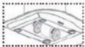
natural_image
Simple line drawing of a curved mechanical component with two circular holes (no text or symbols)natural_image
Line drawing of a cabinet with an open door and directional arrows indicating movement (no text or symbols)
natural_image
Line drawing of a simple cabinet or display unit with a top shelf and side legs (no text or symbols)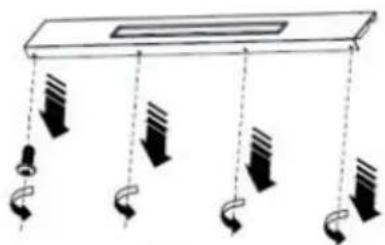
natural_image
Pure diagram of hanging objects with arrows indicating direction (no text or symbols)
natural_image
Symbol of a trash bin crossed with a diagonal line, no text or numbers presentBerlin Brands Group UK Ltd
PO Box 1145
Oxford, OX1 9UW
United Kingdom
Member of Berlin Brands Group
Handwerkerstr. 11
15366 Dahlwitz-Hoppegarten
Deutschland
Congratulations on purchasing this device. Please read the following instructions carefully and follow them to prevent possible damages. We assume no liability for damage caused by disregard of the instructions and improper use. Scan the QR code to get access to the latest user manual and more product information.

CONTENTS
Technical Data 28
Safety Instructions 28
Installation 30
Wall Mounting 31
Airflow Information 35
Install Activated Carbon Filter (Optional) 36
Getting Started 37
Operation 38
Notes on Environmental Protection 39
Device Control via Smartphone 40
Cleaning and Maintenance 42
Dismantling the Cooker Bonnet 44
Troubleshooting 45
Disposal Considerations 46
Declaration of Conformity 46
Product Data Sheet 47
TECHNICAL DATA
| Item number 10041171, 100411 | 72, 10041173, 10041174 |
| WiFi standard | 802.11 b/g/n |
| WiFi frequency | 2.4 GHz |
| WiFi transmission power (max.) | < 20 dBm |
| Power supply 220-240 V ~ 50/60 Hz | |
| Note: You can also purchase an activated carbon filter for this cooker hood under item number 10030727. To do so, visit our website: www.klarstein.co.uk | |
SAFETY INSTRUCTIONS
- Read all instructions carefully before use and keep the user manual in a safe place for future reference.
- The installation work may only be carried out by an electrician or a qualified person. Before using the cooker hood, make sure that the voltage (V) and frequency (Hz) indicated on the cooker hood correspond to the voltage and frequency of the power supply in your household.
• We accept no liability for damage caused by improper use or installation.
• Children under 8 years of age must not use the cooker hood. - The device is not intended for commercial use, only for household and similar use.
- Clean the appliance and the filter regularly to keep the appliance working efficiently.
• Always disconnect the power plug from the socket before cleaning. - Clean the appliance exactly as indicated in the operating instructions.
- Do not use an open fire under the extractor hood.
- If the unit is not functioning normally, contact the manufacturer or a specialist company.
- Children from the age of 8 years and mentally, sensory and physically impaired persons may only use the device if they have been informed in detail about the functions and safety precautions by a supervisor responsible for them beforehand and understand the associated risks.
- If the power cord is damaged, it must be replaced by the manufacturer, an authorised specialist company or a similarly qualified person.
- If the cooker hood is used with cookers that burn gas or other fuels, there must be adequate ventilation in the room.
- Do not flambé under the extractor hood.
- Caution: The surface of the unit may become hot during operation.
Important instructions for installation
- The air must not be discharged into a fl ue used for extracting fl ue gases from gas or other fuels (does not apply to appliances that only return the air to the room).
- Observe all regional regulations for the installation of ventilation systems.
Important notes on exhaust air operation
WARNING
Danger of poisoning from recirculated exhaust gases! Do not operate the appliance in extract air mode if it is operated together with a room air-dependent fi replace and sufficient air circulation is not guaranteed.
Room air-dependent fi replaces such as gas, oil, wood or coal heaters, boilers or instantaneous water heaters draw the air from the room and lead it outdoors through an exhaust pipe or chimney. In extract air mode, air is extracted from the kitchen and neighbouring rooms. Without sufficient supply air, negative pressure is created. Toxic gases from the chimney or exhaust pipe can be sucked back into the living rooms.
- Make sure that sufficient fresh air supply is guaranteed and that the air can circulate.
- A supply air/exhaust air wall box is not sufficient to ensure compliance with the limit value.
Safe operation is only possible if the negative pressure at the location of the fi replace does not exceed 4 Pa (0.04 mbar). This can be achieved if the air required for combustion can flow in through non-closable openings in doors and windows in conjunction with a supply air / exhaust air wall box. In any case, have a master chimney sweep advise you and assess the entire ventilation system of the house. If necessary, they can tell you the necessary measure for ventilation.
If the cooker hood is used exclusively in recirculation mode, operation is possible without restriction.
Important note on dismantling the unit
- Disassembly is the same as installation/assembly in reverse order.
- Have a second person help you during disassembly to avoid injury.
INSTALLATION
Important information before installing the appliance
- Clean the surrounding area thoroughly before and after installation so that no dust or construction debris can be sucked in during commissioning.
- Only place the appliance in a suitable location.
- Check the wall for its load-bearing capacity.
- Check the routing of electrical and other cables on and in the wall or ceiling so that they are not drilled into.
- Check the condition and load-bearing capacity of the electrical cables.
• Installation of the unit by a specialist is recommended. - The extractor bonnet should be installed at a height of 65-75 cm above the hob. When installing, strictly observe the minimum distance between the hob and the extractor bonnet and follow the description of the work steps in the "Wall mounting" section and all other instructions.
Installation with exhaust air opening to the outside
- In the version with exhaust air to the outside, the vapours are extracted via an exhaust air hose attached to the connection ring.
- The diameter of the exhaust air hose must correspond to the diameter of the connection ring.
- The exhaust air hose must not be routed through a shaft together with gas pipes, hot air pipes etc.
- Route the exhaust hose as straight as possible away from the bonnet. The maximum permissible outward bending is 120^ .
- If a smoke check damper is used or planned, check that it can open and close freely after the exhaust air hose has been installed.
- The cooker bonnet can be equipped with one (top) or two (top and rear) exhaust openings. As a rule, the cooker bonnet is initially equipped for use of the upper extractor opening as a cooker bonnet.
- The openings that are not needed are covered with a plastic cover. This plastic cover can be easily removed by turning it anticlockwise and optionally attached to another opening that is not needed.
Use of the cooker bonnet as an exhaust bonnet (with exhaust air to the outside):
- If the cooker bonnet is equipped with a carbon filter at the factory, this must be removed for exhaust air operation. Use only makes sense if you operate your cooker bonnet in recirculation mode.
Conversion of the cooker bonnet into a recirculation bonnet:
- If you want to use the cooker bonnet as a recirculation bonnet, you must fit the activated charcoal filter(s) to the fan motor before using the bonnet. If not included in the scope of delivery, you must obtain the activated charcoal filter(s) from the supplier of your cooker bonnet.
WALL MOUNTING
Power connection
- Do not connect the unit to the mains until it has been properly installed.
- Never install the appliance if the information on the rating plate (V) does not match your mains voltage. The rating plate is located inside the appliance, behind the grease filter.
- If the cooker bonnet is equipped with a standard plug, connect it to an easily accessible standard socket.
- If the appliance is not equipped with a connection plug, a two-pole, standard-compliant switch with a contact gap of 3 mm must be installed by an authorised specialist in an easily accessible place.
- When the cooker bonnet is connected to the mains, all indicator lights light up briefly and the cooker bonnet switches to standby mode (accompanied by a beep).
Installation with exhaust air (fume cupboard outside):
Note: Failure to fit the screws or fixing device in accordance with these instructions may result in electrical hazards.
Note: Observe the safety instructions for operating the unit when the air is discharged to the outside. If the cooker hood is in operation at the same time as an appliance that draws its energy from a source other than electricity, the negative pressure in the room must not exceed 4 Pa (4 x 10⁻⁵ bar).
Mounting the cooker bonnet
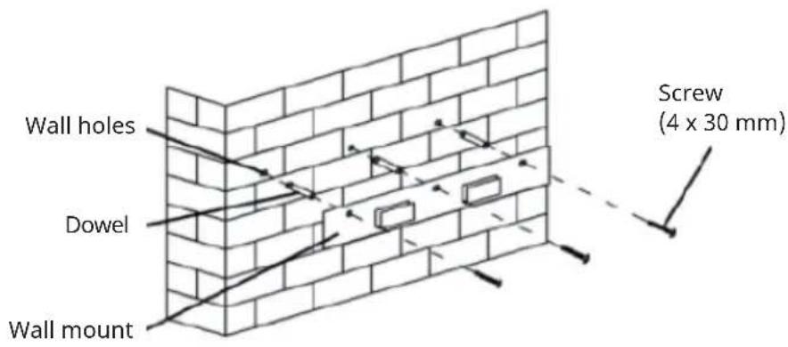
- Drill 3 x 8 mm holes for the wall bracket.
- Fix the bracket to the wall with dowels and screws and tighten.
natural_image
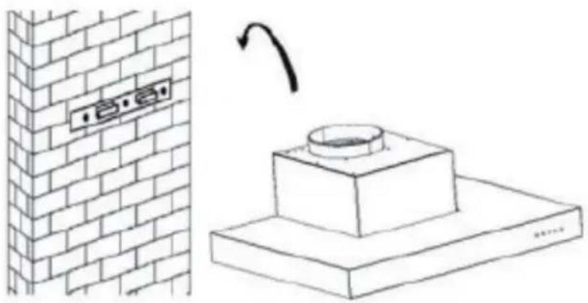
Diagram showing a brick wall with electrical outlets and a mechanical component with a rotating arrow (no text or symbols)- Lift the cooker bonnet and hang it on the wall bracket.
- Remove the metal grease filter and mark the mounting holes on the back of the cooker bonnet on the wall.
- Remove the cooker bonnet again. Drill four holes with a diameter of 8 mm at the marked points. Insert the dowels into the holes.
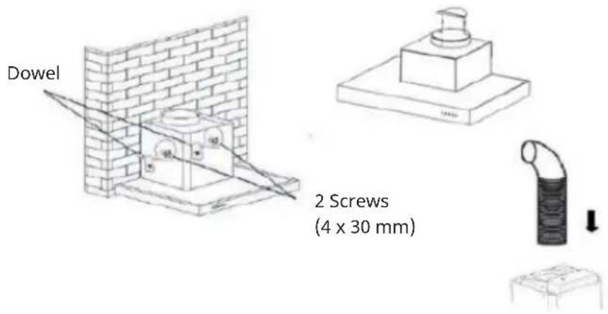
- Hang the cooker bonnet on the wall bracket and fix it to the dowels with the screws from the inside of the bonnet.
- Attach the exhaust air hose to the outlet.
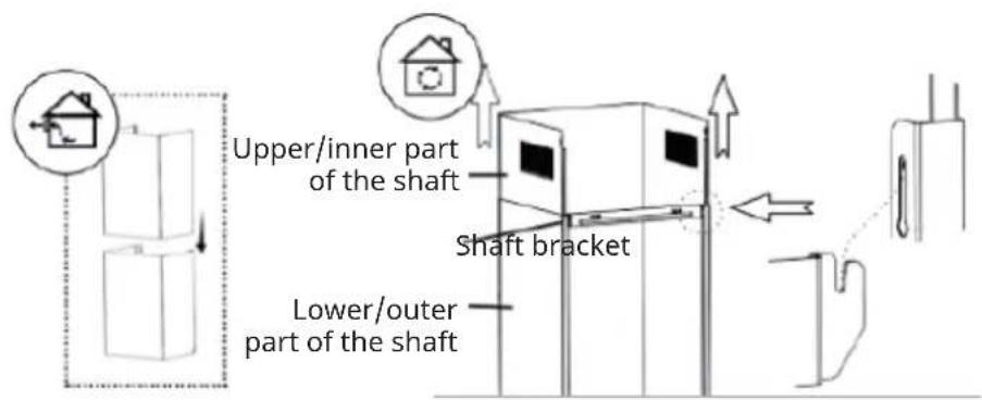
- Push the upper part of the shaft into the lower part. Pay attention to the position of the ventilation openings depending on whether they are used for exhaust air or recirculation air (see illustration).
- Attach the shaft bracket to the lower/outer part of the shaft.
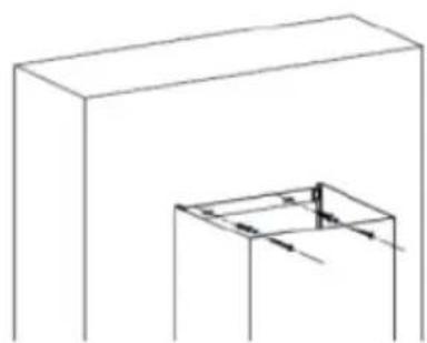
natural_image
Simple line drawing of two 3D rectangular blocks with internal cutouts and directional arrows (no text or symbols)- Place the shaft on the housing of the cooker bonnet.
- Mark the mounting holes on the wall and pre-drill the holes at the marks.
• Fix the lower shaft bracket to the wall with 2 dowels and screws (4 mm x 30 mm).
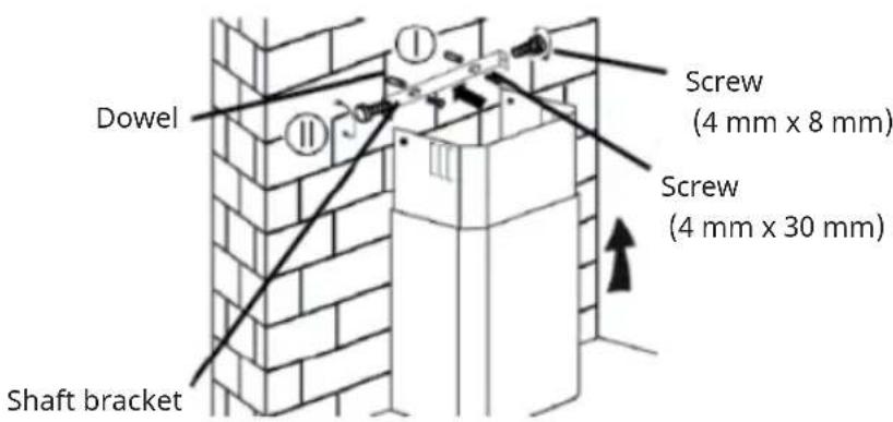
- Pull the upper/inner part of the shaft up to the desired height. Mark the mounting holes for the upper shaft bracket on the wall and pre-drill the holes at the marked locations.
- Fix the upper shaft bracket to the wall with 2 dowels and 2 screws (4 x 30 mm) in the pre-drilled holes.
- Fasten the upper/inner part of the shaft to the bracket with 2 screws (4 x 8 mm).
AIRFLOW INFORMATION
Note: The illustrations are for reference only. The product you have purchased and the local conditions may differ from these.
| 123 | ||
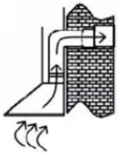 | 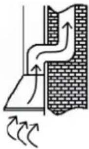 | 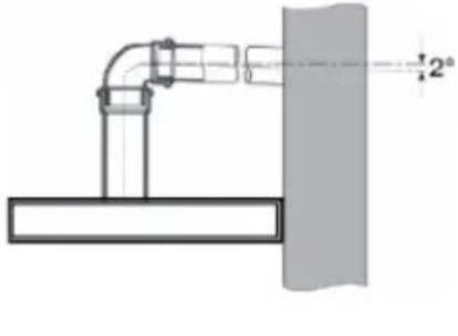 |
| Exhaust air into the open | Exhaust air via air shaft/chimney | Angle of inclination of the exhaust air duct |
- The exhaust duct should be as short and straight as possible.
- To avoid excessive noise or reduced extraction performance, the diameter of the exhaust duct should not be smaller than 150 mm.
- Only use or shape arches with a large radius, small radii reduce the extraction performance of the cooker bonnet.
- Only use smooth piping or flexible hoses made of non-combustible material for the exhaust air line.
- If the exhaust air duct is laid horizontally, a minimum gradient of 1 cm per metre or an angle of inclination of 2° must be maintained (Figure 3), otherwise condensation can get into the extractor fan motor.
- If the exhaust air is directed into an exhaust air duct, the end of the connection piece must be aligned in the direction of flow.
- If the extract air duct is routed through cool rooms, attics, etc., there may be a large temperature gradient within the individual duct sections, resulting in condensation or condensation water. Therefore, it is necessary to insulate the exhaust air duct. In some cases, a condensation water barrier must be installed in addition to adequate insulation.
- The manufacturer is not liable for faults resulting from non-compliance with the above instructions and regulations.
Use as recirculation bonnet
This appliance has been prepared for recirculation operation at the factory. To do this, check inside the cooker bonnet that the activated charcoal filters have been fitted to the right and left of the motor appliance.
INSTALL ACTIVATED CARBON FILTER (OPTIONAL)
Note: You can purchase an additional activated charcoal filter for this cooker bonnet under item number 10030727. To do so, visit our website: www.klarstein.co.uk
- Remove the metal grease filter.
- The carbon filter is mounted in two parts to the right and left of the motor. Check that the teeth correspond with the direction of rotation of the respective side.
- Turn the activated carbon filter onto the motor housing (usually clockwise).
natural_image
Pure electrical circuit lines without any symbols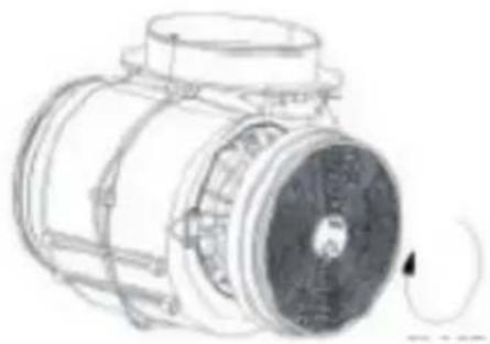
natural_image
Technical line drawing of a mechanical component with no visible text or symbols
natural_image
Simple line drawing of a curved mechanical component with two circular holes (no text or symbols)Note: The illustrations are for reference only. The actual product may differ from these.
GETTING STARTED
Before first use
- Make sure that the cooker bonnet has not been damaged during transport.
- Installation and connection to the power supply must be carried out by qualified persons in accordance with the operating instructions and in compliance with local requirements.
Instructions for use
- The appliance must only be used with the grease filter in place. Otherwise grease could be deposited in the appliance.
- Do not use naked flames under the cooker bonnet. High flames could damage the cooker bonnet or cause a fire of the grease deposits in the cooker bonnet.
- When using a gas cooker, make sure that it is not used without cooking utensils. Open flames could damage parts of the appliance due to the rising heat.
- Due to the risk of fire, when deep-frying and cooking with oil, it must be ensured that permanent monitoring of the preparation is guaranteed.
Note: The risk of spontaneous combustion increases the more often oils or greases are reused.
Exhaust air mode
The extracted air is discharged to the outside via the exhaust air pipe. For this purpose, your house must have an exhaust air shaft or an exhaust air duct to the outside.
When operating the cooker bonnet in exhaust air mode and simultaneously operating chimney-dependent firing systems (e.g. coal stove), a sufficient supply of fresh air must be ensured in the installation room of the cooker bonnet. In any case, contact your responsible chimney sweep. If there is no permanently installed exhaust air pipe or no separate exhaust air shaft, you must switch the cooker bonnet to recirculation mode (see chapter "Installation").
Convection functionality
The extracted air is filtered through a carbon filter (also called an activated carbon filter) and circulated in the room. The charcoal filter retains the odours produced during cooking and the filtered air is returned to the kitchen through side or top air vents.
If the cooker bonnet is used in recirculation mode, a room air dependent fire can be operated at the same time.
It is recommended to switch on the appliance a few minutes before starting to cook. To improve the performance of the cooker bonnet, you should pull out the steam collector (if present). Set the power level according to the amount of steam and odour to be extracted. Leave the cooker bonnet running for approx. 5 to 10 minutes after cooking. This frees the kitchen air from residual vapours and odours.
OPERATION
Control panel
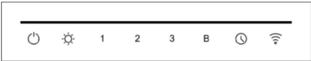
Button functions
| On / off button | |
| Light buttonBriefly press this button to switch the light on or offAdjust the colour temperature (Kelvin): Press and hold this button in operating mode/standby mode to adjust the Kelvin value. In Kelvin adjustment mode, the light button flashes. Press "1" briefly to adjust the Kelvin value (Kelvin value from 280 K to 6500 K). There are a total of 6 adjustment levels.The brightness can be adjusted by briefly pressing the WLAN key.There are a total of 3 brightness settings: 100 %, 75 % or 50 %, which are cycled through by pressing the WLAN button several times. | |
| 1 | Level 1 - low speed |
| 2 | Level 2 - medium speed |
| 3 | Level 3 - high speed |
| B | Booster functionAfter 5 minutes, the speed automatically changes to level 3. |
| Automatic switch-offPress this button briefly to switch the appliance off automatically after 5 minutes. Hold the button down for a long time to deactivate the automatic switch-off. |

WLAN button
- In standby mode, press and hold the Wi-Fi button to activate the Wi-Fi function. The WLAN symbol starts flashing. Establish the connection to the WLAN network (see section "Device control via smartphone"). As soon as the connection has been successfully established, the WLAN symbol lights up permanently. If no WLAN connection is established within 3 minutes, the WLAN symbol stops flashing and the appliance automatically switches to standby mode.
NOTES ON ENVIRONMENTAL PROTECTION
- Make sure there is sufficient air supply during cooking so that the cooker hood can work efficiently and with low operating noise.
- Adjust the fan speed to the amount of steam produced while cooking. Use the intensive mode only when necessary. The lower the fan speed, the less energy is consumed.
- If large amounts of steam are produced when cooking, select a higher fan speed in time. If the cooking steam has already spread throughout the kitchen, the cooker hood must be operated for longer.
- Switch off the cooker hood when it is no longer needed.
- Switch off the lighting when it is no longer needed.
- Clean the filter at regular intervals and replace it if necessary to increase the effectiveness of the ventilation system and prevent fire hazards.
- Always put the lid on when cooking to reduce cooking steam and condensation.
DEVICE CONTROL VIA SMARTPHONE
If you integrate your Klarstein appliance into your home WLAN, you can operate it conveniently via the associated Klarstein app. The app not only allows you to control the appliance remotely via your smartphone, but also gives you access to recipes and further information.
Follow these steps to connect your smartphone to your Klarstein appliance:
- First download the Klarstein app by scanning the QR code with your smartphone (see below) or download it directly from the App Store or Google Play.
- Make sure that your smartphone is connected to the same WiFi network that your Klarstein device is to be connected to.
- Open the Klarstein app.
- Log in with your account. If you don't have an account yet, register in the Klarstein app.
- Follow the instructions in the app.
App download
Use the scan function of your mobile phone to scan the QR code and save the app on your smartphone.
Note: Further instructions on how to use the app and help on how to connect to your device are provided by the app when you open it for the first time.
| iOS Android | |
Troubleshooting connection problems
If your Klarstein device cannot be found in the WLAN, check the following:
- The device is not plugged in. Make sure that your unit is plugged into a power outlet.
- The unit is not in pairing mode. Make sure that the WiFi indicator (LED) on the control panel of the smart device is flashing as described in the "Reset WiFi settings" instruction of your smart device (instructions can usually be found under Device connection).
- The WiFi access point does not operate on 2.4 GHz. Make sure your access point is operating on the 2.4 GHz band and that you have your own SSID on the 2.4 GHz band. If you are unsure about the operating band of your access point, please contact your internet provider.
Important: Please note that if your WiFi router has a dual band - i.e. operates in both the 2.4 GHz and 5 GHz bands - you must separate the SSIDs for each band and use the 2.4 GHz SSID for the connection
-
Check the firewall settings of your WiFi network. The firewall setting of your WiFi network may not allow the Klarstein App to configure the WiFi settings on your smart device. Please ensure that you do not use a public WiFi network, e.g. airports, dormitories, companies, etc.
-
Different login data in the smartphone and in the app. Make sure that the WiFi login details entered in the Klarstein app match those to which your smartphone is connected.
If you have followed the above points and your smartphone still cannot connect to the app, please contact us by email for assistance: appsupport@go-bbg.com
CLEANING AND MAINTENANCE
CAUTION
Risk of electric shock! Do not use a steam cleaner for the cleaning.
- Make sure that the appliance is switched off.
- Unplug the appliance before cleaning it.
• Always allow the appliance and its components to cool down before cleaning them. - Do not use cloths, chemicals or alcohol for cleaning as these may damage the surface. Electrical/electronic parts must not be cleaned.
- Do not use harsh or corrosive cleaning agents. Do not use abrasive cleaning agents or alkaline rinsing agents (pH value above 7).
- Maintenance and inspection should be carried out regularly. In case of visible damage, strong odour or excessive overheating of components, stop using the appliance.
- Clean the appliance according to the instructions. There is a fire hazard if this is not observed.
Stainless steel surfaces
Clean the stainless steel surface weekly. For cleaning, use a soft cloth and lukewarm water and use a cleaning agent suitable for stainless steel. Make sure you wipe along the grain of the stainless steel to avoid unsightly scratches.
Control panel interface
Clean the control panel surface weekly. Use a soft cloth and lukewarm water for cleaning. Make sure that the cloth is clean and not too wet before cleaning. Wipe away excess moisture with a dry, soft cloth.
Monthly cleaning of the grease fi Iters
Clean the fi liter every month to avoid a fi re hazard. The fi liter collects grease, smoke and dust and thus influences the efficiency of the cooker hood. If the fi liter is not cleaned, grease residues will collect there.
To clean the grease filters:
- Remove the grease filter.
-
Perform one of the following steps to clean the filter:
-
Manual cleaning (max. 30 °C): Soak the filter in water with a mild, non-caustic grease-dissolving detergent for about 3 minutes
- Cleaning in the dishwasher (max. 30 °C): Place the filter in the dishwasher and run a programme with a mild, non-caustic, grease-dissolving detergent.
Note: It is advisable not to use rinse aid. The filter should be cleaned separately from dishes and kitchen utensils. Carefully brush the filter with a soft brush. Do not apply too much pressure to avoid damaging the filter. The filter may fade to grey. This is normal and is not covered by the warranty.
Replace activated carbon filter
Replace the activated charcoal filter every 3 to 6 months (see section: "Install activated carbon filter (optional)").
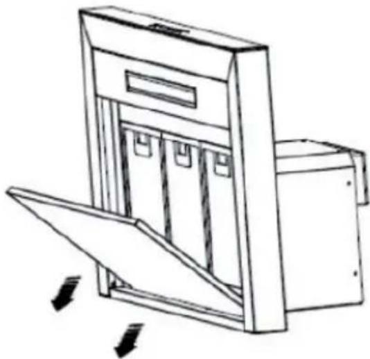
Replacing the lamp
- The lamp may only be replaced by a qualified electrician.
- Disconnect all power connections before opening the appliance.
- There is a risk of burns! Always allow the lamp to cool down before replacing it.
- Always use gloves or a cloth to avoid direct contact with your hands. Direct contact can shorten the life of the lamp.
- Replace the lamp with a lamp of the same type and amperage.
natural_image
Line drawing of a cabinet with an open door and directional arrows indicating movement (no text or symbols)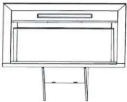
natural_image
Line drawing of a simple cabinet or display unit with a top shelf and side legs (no text or symbols)
natural_image
Pure diagram of hanging objects with arrows indicating direction (no text or symbols)
Note: Remember to reattach everything after inserting the new lamp and fix all screws in the same position
DISMANTLING THE COOKER BONNET
- Make sure that the on/off switch is in the "0" position.
- Unplug the power cord from the wall socket.
- Remove the cooker bonnet from the wall or cabinet.
- Remove the filter. Dispose of the filters at a collection point for the recycling of waste electrical and electronic equipment.
- Remove the motor. Dispose of the motor at a collection point for the recycling of waste electrical and electronic equipment.
- Dispose of the rest of the cooker bonnet at your local recycling centre.
TROUBLESHOOTING
- Repairs to the electrical system may only be carried out by a qualified electrician, and local regulations must be observed. If in doubt, contact the manufacturer, customer service or an authorised specialist company.
- Disconnect all power connections before opening the appliance.
| Problem Potential cause | Solution | |
| The light turns on but the engine does not run. | The ventilation is blocked. | Switch off the appliance and have it repaired by qualified personnel. |
| The engine is damaged. | ||
| The light is off and the engine does not run. | The lamp is broken. Replace the bulb. | |
| The plug is loose. Plug the power plug securely into the wall socket. | ||
| The housing vibrates. The motor blade of the fan is damaged. | Switch off the appliance and have it repaired by qualified personnel. | |
| The air is not extracted properly. | The distance between the cooker and the extractor bonnet is too far. | Reduce the distance to 65-75 cm. |
DISPOSAL CONSIDERATIONS
natural_image
Symbol of a trash bin crossed with a diagonal line, no text or numbers presentIf there is a legal regulation for the disposal of electrical and electronic devices in your country, this symbol on the product or on the packaging indicates that this product must not be disposed of with household waste. Instead, it must be taken to a collection point for the recycling of electrical and electronic equipment. By disposing of it in accordance with the rules, you are protecting the environment and the health of your fellow human beings from negative consequences. For information about the recycling and disposal of this product, please contact your local authority or your household waste disposal service.
DECLARATION OF CONFORMITY
CE UK CA
Manufacturer:
Chal-Tec GmbH, Wallstrasse 16, 10179 Berlin, Germany.
Importer for Great Britain:
Berlin Brands Group UK Ltd
PO Box 1145
Oxford, OX1 9UW
United Kingdom
Hereby, Chal-Tec GmbH declares that the radio equipment type Alinea Smart is in compliance with Directive 2014/53/EU. The full text of the EU declaration of conformity is available at the following internet address: use.berlin/10041171
For Great Britain: Hereby, Chal-Tec GmbH declares that the radio equipment type Alinea Smart is in compliance with the relevant statutory requirements. The full text of the declaration of conformity is available at the following internet address: use.berlin/10041171
PRODUCT DATA SHEET
Information according to Regulation (EU) No. 65/2014
Measurement and calculation methods according to EN 61591:1997+A1:2006+A2:2011+A11:2014+A12:2015
| Item number | 10041171, 10041172, 10041173, 10041174 | ||
| Description Symbol Value Unit | |||
| Annual Energy Consumption AEC | hood | 11,6 kWh/Year | |
| Energy Efficiency class A++ | |||
| Fluid Dynamic Efficiency FDE | hood | 32,8 | |
| Fluid Dynamic Efficiency class A | |||
| Lighting Efficiency LE | hood | 49 (10041171 & 10041773)44 (10041772 & 10041174) | Lux/W |
| Lighting Efficiency class A | |||
| Grease Filtering Efficiency GFE | hood | 66,1 (10041171 & 10041773)66,8 (10041772 & 10041174) | % |
| Grease Filtering Efficiency class D | |||
| air flow at minimum and maximum speed in normal use, intensive or boost excluded | 316,0 / 505,9 m^3/h | ||
| air flow at intensive or boost setting | 577,8 m^3/h | ||
| airborne acoustical A-weighted sound power emissions at minimum and maximum speed available in normal use | 52 / 63 dB | ||
| airborne acoustical A-weighted sound power emissions at intensive or boost setting | 65 | dB | |
| power consumption in off mode | P_o | 0,41 W | |
| power consumption in standby mode | P_s | 0.90 W | |
| Contact details Chal-Tec GmbH, Wallstraße 16, 10179, Berlin, Germany | |||
Cher client, chère cliente,
SOMMAIRE
Fiche technique 50
natural_image
Diagram showing a brick wall with electrical outlets and a mechanical component with a rotating arrow (no text or symbols)natural_image
Simple line drawing of two 3D rectangular blocks with internal cutouts and directional arrows (no text or symbols)Vis
(4 mm × 8 mm)
Vis
(4 mm × 30 mm)
Support de puits

natural_image
Technical line drawing of a mechanical component with no visible text or symbols
natural_image
Simple line drawing of a curved object with circular elements inside, no text or symbols present.natural_image
Line drawing of a mechanical device with a folding blade and internal compartments, showing directional arrows (no text or symbols)
natural_image
Line drawing of a simple cabinet or display unit with a top shelf and side legs (no text or symbols)
natural_image
Pure diagram of hanging objects with arrows indicating direction (no text or symbols)natural_image
Symbol of a trash bin crossed with a diagonal line, no text or numbers presentDÉCLARATION DE CONFORMITÉ

Fabricant :
Chal-Tec GmbH, Wallstraße 16, 10179 Berlin, Allemagne.
Berlin Brands Group UK Ltd
PO Box 1145
Oxford, OX1 9UW
United Kingdom
FICHE DE DONNÉES PRODUIT
ÍNDICE
Datos técnicos 72
natural_image
Diagram showing a brick wall with electrical outlets and a mechanical component with a rotating arrow (no text or symbols)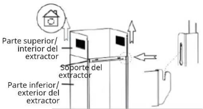
natural_image
Simple line drawing of two 3D rectangular blocks with internal cutouts and directional arrows (no text or symbols)natural_image
Pure electrical circuit lines without any symbols
natural_image
Technical line drawing of a mechanical component with no visible text or symbols
natural_image
Technical line drawing of a mechanical component with no visible text or symbolsnatural_image
Line drawing of a mechanical device with a folding blade and internal compartments, showing directional arrows (no text or symbols)
natural_image
Line drawing of a simple cabinet or display unit with a top shelf and side legs (no text or symbols)
natural_image
Pure diagram of hanging objects with arrows indicating direction (no text or symbols)natural_image
Symbol of a trash bin crossed with a diagonal line, no text or numbers presentBerlin Brands Group UK Ltd
PO Box 1145
Oxford, OX1 9UW
United Kingdom
INDICE
Dati tecnici 94
natural_image
Simple line drawing of two 3D rectangular blocks with internal cutouts and directional arrows (no text or symbols)
natural_image
Technical line drawing of a mechanical component with no visible text or symbols
natural_image
Simple line drawing of a curved object with circular elements, no text or symbols presentnatural_image
Line drawing of a mechanical device with a folding blade and internal compartments, showing directional arrows (no text or symbols)
natural_image
Line drawing of a simple cabinet or display unit with a top shelf and side legs (no text or symbols)
natural_image
Pure diagram of hanging objects with arrows indicating direction (no text or symbols)natural_image
Symbol of a trash bin crossed with a diagonal line, no text or numbers presentBerlin Brands Group UK Ltd
PO Box 1145
Oxford, OX1 9UW
United Kingdom

- INHALTSVERZEICHNIS
- INFORMATIONEN ZUM LUFTSTROM
- Member of Berlin Brands Group
- Dahlwitz-Hoppegarten
- CONTENTS
- TECHNICAL DATA
- SAFETY INSTRUCTIONS
- Important instructions for installation
- Important notes on exhaust air operation
- WARNING
- Important note on dismantling the unit
- INSTALLATION
- Important information before installing the appliance
- Installation with exhaust air opening to the outside
- Use of the cooker bonnet as an exhaust bonnet (with exhaust air to the outside):
- Conversion of the cooker bonnet into a recirculation bonnet:
- WALL MOUNTING
- Power connection
- Installation with exhaust air (fume cupboard outside):
- Mounting the cooker bonnet
- AIRFLOW INFORMATION
- Use as recirculation bonnet
- INSTALL ACTIVATED CARBON FILTER (OPTIONAL)
- GETTING STARTED
- Before first use
- Instructions for use
- Exhaust air mode
- Convection functionality
- OPERATION
- WLAN button
- NOTES ON ENVIRONMENTAL PROTECTION
- DEVICE CONTROL VIA SMARTPHONE
- App download
- Troubleshooting connection problems
- CLEANING AND MAINTENANCE
- CAUTION
- Stainless steel surfaces
- Control panel interface
- Monthly cleaning of the grease fi Iters
- To clean the grease filters:
- Replace activated carbon filter
- Replacing the lamp
- DISMANTLING THE COOKER BONNET
- TROUBLESHOOTING
- DISPOSAL CONSIDERATIONS
- DECLARATION OF CONFORMITY
- CE UK CA
- Manufacturer:
- Importer for Great Britain:
- PRODUCT DATA SHEET
- Information according to Regulation (EU) No. 65/2014
- SOMMAIRE
- DÉCLARATION DE CONFORMITÉ
- Fabricant :
- FICHE DE DONNÉES PRODUIT
- ÍNDICE
- INDICE
Brand : Klarstein
Model : Alinea Smart
Category : Basket