USER MANUAL Brisa Klarstein
Berlin Brands Group UK Limited
PO Box 42
272 Kensington High Street
London, W8 6ND
United Kingdom
Dear customer,
Congratulations on your purchase. Please read the following instructions carefully and follow them to prevent potential damage. We accept no liability for damage caused by disregarding the instructions and improper use. Please scan the QR code to access the latest operating instructions and further information about the product.

CONTENTS
Safety Instructions 26
Device Overview 28
Installation 29
Installation of the Cooker Bonnet 34
Operation 38
Cleaning and Maintenance 39
Troubleshooting 41
Notes on Environmental Protection 41
Product Data Sheet 42
Disposal Considerations 44
Manufacturer & Importer (UK) 44
TECHNICAL DATA
| Article number | 10041402, 10046381, 10046382 |
| Power supply 220-240 V ~ 50/60 Hz | |
SAFETY INSTRUCTIONS
- Read all instructions carefully before use and keep this user manual in a safe place for future reference.
- The installation work may only be carried out by an electrician or a qualified person. Before using the cooker hood, make sure that the voltage (V) and frequency (Hz) indicated on the cooker hood correspond to the voltage and frequency of the power supply in your household.
- We accept no liability for damage caused by improper use or installation.
Children under 8 years of age must not use the cooker hood.
- The appliance is intended for use in the home and similar environments only. It is not intended for commercial use.
- Clean the appliance and the filter regularly to keep the appliance working efficiently.
- Always disconnect the power plug from the socket before cleaning.
- Clean the appliance exactly as indicated in the operating instructions.
- Do not use an open fire under the extractor hood.
- If the unit is not functioning normally, contact the manufacturer or a specialist company.
- Children from the age of 8 years and mentally, sensory and physically impaired persons may only use the device if they have been informed in detail about the functions and safety precautions by a supervisor responsible for them beforehand and understand the associated risks.
- If the power cord is damaged, it must be replaced by the manufacturer, an authorised specialist company or a similarly qualified person.
- If the cooker hood is used with cookers that burn gas or other fuels, there must be adequate ventilation in the room.
- Do not flambé under the extractor hood.
- Caution: The surface of the unit may become hot during operation.
Important instructions for installation
- The air must not be discharged into a flue used for extracting flue gases from gas or other fuels (does not apply to appliances that only return the air to the room).
- Observe all regional regulations for the installation of ventilation systems.
Important notes on exhaust air operation
WARNING
Danger of poisoning from recirculated exhaust gases! Do not operate the appliance in extract air mode if it is operated together with a room air-dependent fireplace and sufficient air circulation is not guaranteed.
Room air-dependent fireplaces such as gas, oil, wood or coal heaters, boilers or instantaneous water heaters draw the air from the room and lead it outdoors through an exhaust pipe or chimney. In extract air mode, air is extracted from the kitchen and neighbouring rooms. Without sufficient supply air, negative pressure is created. Toxic gases from the chimney or exhaust pipe can be sucked back into the living rooms.
- Make sure that sufficient fresh air supply is guaranteed and that the air can circulate.
- A supply air/exhaust air wall box is not sufficient to ensure compliance with the limit value.
Safe operation is only possible if the negative pressure at the location of the fireplace does not exceed 4 Pa (0.04 mbar). This can be achieved if the air required for combustion can flow in through non-closable openings in doors and windows in conjunction with a supply air / exhaust air wall box. In any case, have a professional chimney sweep advise you and assess the entire ventilation system of the house. If necessary, they can tell you the necessary measure for ventilation.
If the cooker hood is used exclusively in recirculation mode, operation is possible without restriction.
Important note on dismantling the unit
- Disassembly is the same as installation/assembly in reverse order.
- Have a second person help you during disassembly to avoid injury.
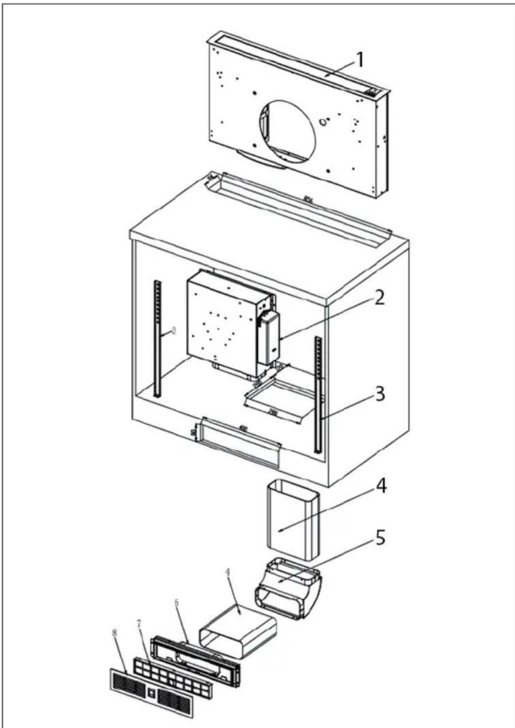
| 1 | Cooker Hood | 5 | Support plate for plastic pipe |
| 2 | Motor housing | 6 | Air outlet |
| 3 | Mounting panel | 7 | Activated carbon filter |
| 4 | Plastic pipe | 8 | Cover of the activated carbon filter |
INSTALLATION
Installation with exhaust air
Note: Observe the safety instructions for operating the unit when the air is discharged to the outside. If the cooker hood is in operation at the same time as an appliance that draws its energy from a source other than electricity, the negative pressure in the room must not exceed 4 Pa (4 x 10⁻⁵ bar).
Installation with convection function
If you do not have an outdoor extractor, you do not need an exhaust air pipe. The installation corresponds to installation with external ventilation.
Preparation
If you have an extractor to the outside, you can install the extractor hood as shown in the picture on the right. The flue should have a diameter of at least 150mm and be made of enamel, aluminium or a flexible, heat-resistant tube.
- Switch off the device before installation and pull the power plug out.
- The extractor hood should be placed at a height of 65 - 75cm above the hob.
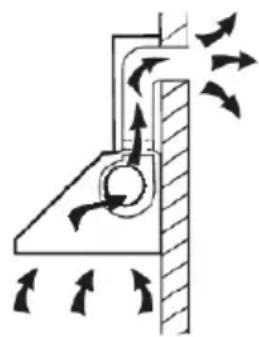
During installation, the minimum distance between the hob and the cooker bonnet must be strictly observed and the numbering of the work steps as well as the additional instructions must be followed.
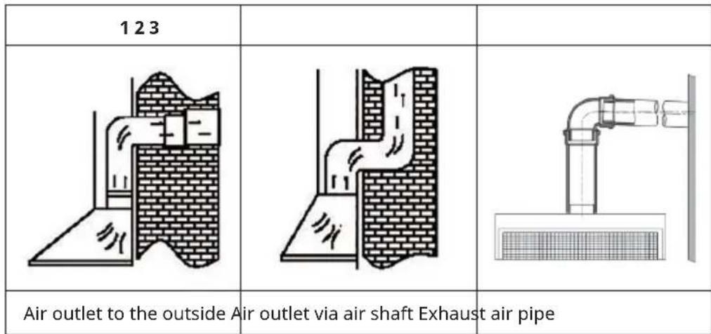
Installation with exhaust air to the outside
The vapours are extracted with an exhaust air hose attached to the connection ring.
The diameter of the exhaust hose must match the diameter of the connection ring. If a smoke check valve is used or planned, it must be checked that it can be opened and closed easily after the exhaust air hose has been installed. The cooker hood can be equipped with one (top) or two (top and rear) exhaust openings.
Generally, the cooker bonnet is initially equipped for use of the upper extractor opening as a extractor bonnet. The openings that are not needed are covered with a plastic cover. This plastic cover can be easily removed by turning it anticlockwise and optionally attached to another opening that is not needed.
Use of the cooker bonnet as an exhaust bonnet (with exhaust air to the outside)
If the cooker bonnet is equipped with an activated carbon filter at the factory, this must be removed. It is only useful if you operate your cooker bonnet in recirculation mode.
Conversion of the cooker hood into a recirculation hood
If you want to use a suitably equipped cooker bonnet as a recirculation bonnet, you must fit the activated charcoal filter(s) to the fan motor before using the bonnet. The activated charcoal filter(s) is/are included with some models. Otherwise, you must obtain the activated charcoal filter(s) from the supplier of your cooker bonnet.
Important notes for the installation of exhaust air pipes
The following rules must be strictly observed to guarantee optimum air extraction: Failure to follow these instructions will reduce the performance and increase the noise level of the cooker hood.
- Lay the exhaust pipe as short and straight as possible.
- To avoid excessive noise or reduced extraction performance, the diameter of the exhaust pipe should not be smaller than 150~mm .
- Do not use a smaller exhaust pipe and do not constrict it.
- Only use or shape bends with a large radius. Small radius bends reduce the extraction performance of the bonnet.
- Only use smooth piping or flexible hoses made of non-flammable materials as exhaust air pipes.
- When using flexible pipes, the pipe must always be installed tightly in order to minimise pressure loss.
-
If the exhaust air pipe is laid horizontally, a minimum gradient of 1 cm per metre or an angle of inclination of 2^ must be maintained. Otherwise condensation water could run into the motor of the cooker bonnet.
-
The angle of the bend of the exhaust air pipe should not be less than 120^ . Align the pipe horizontally. Alternatively, the pipe should go up from the starting point and be led to an outer wall.
- If the exhaust air is led into an exhaust air duct, the end of the inlet connection must be directed in the direction of flow.
- Do not connect the hood's exhaust pipe to an existing ventilation system that is being used for another device, such as a fireplace.
- If the extract air pipe is routed through cool rooms, attics, etc., there may be a large temperature gradient within the individual parts of the pipe, resulting in condensation. This requires insulation of the exhaust air pipe.
- In some cases, a condensation water barrier must be installed in addition to sufficient insulation.
- All installation work must only be carried out by a qualified electrician or a qualified person.
- After installation, make sure that the cooker hood is horizontal in order to prevent grease from collecting on one side.
- Make sure that the exhaust duct selected for installation complies with the relevant standards and is fire resistant.
Electrical connection
Before connecting the cooker bonnet, check that the voltage (V) indicated on the type plate corresponds to the power supply in your home. Never install the appliance if the information on the rating plate does not match your mains voltage. The type plate is located inside the appliance, behind the grease filter.
If the appliance is not equipped with a connection plug, a two-pole, standard-compliant switch with a contact gap of 3mm must be installed by an authorised specialist in an easily accessible place. If the cooker bonnet is equipped with a standard plug, connect it to an easily accessible power socket.
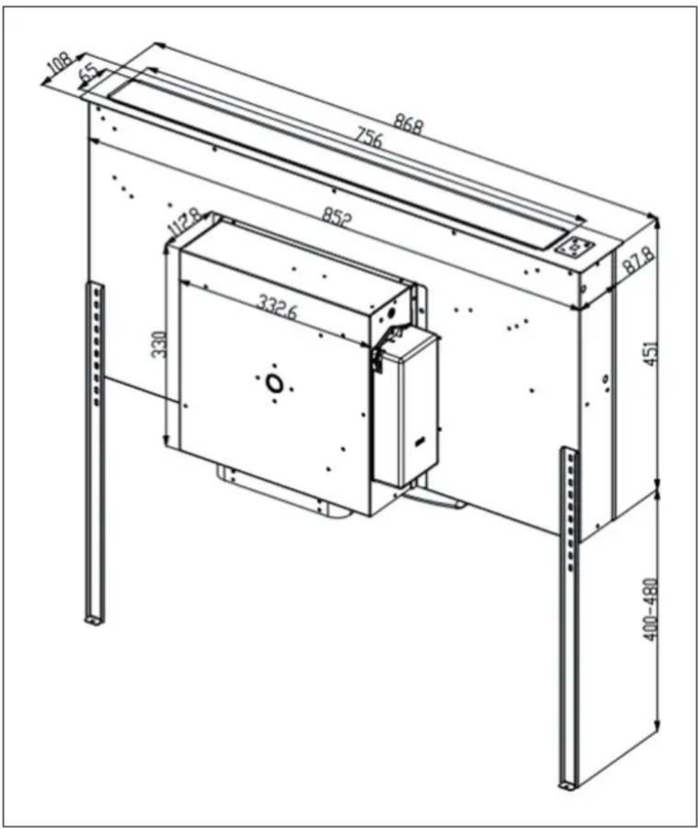
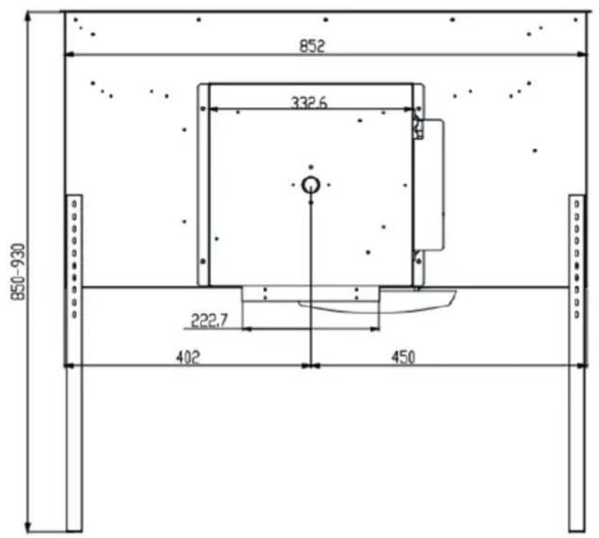
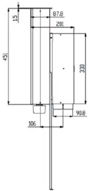
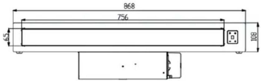
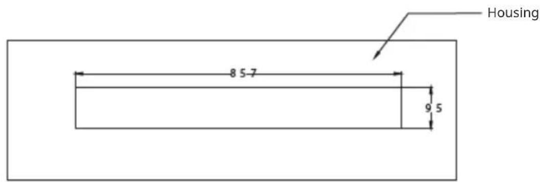
Hole size: 857 × 95 ~mm
INSTALLATION OF THE COOKER BONNET
Parts overview
1
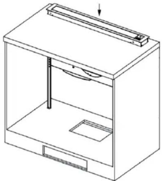
Cut out the opening according to the indicated hole size. Install the cooker bonnet in the housing.
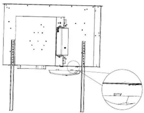
2
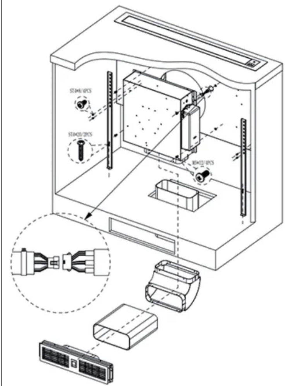
- Align part E to the appropriate height.
- Connect part A and part E with 4 screws (part H).
- Secure part E to the plate with 2 screws (part F).
- Connect part A and part B with 4 screws (part G).
- Join part B and part C with aluminium foil tape (part J).
- Connect part C and part D with screws or aluminium foil tape (part J).
- Connect part I and part C with aluminium foil tape (part J).
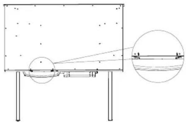
3
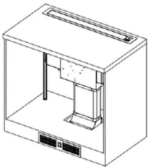
The installation is now complete.
4
According to the bayonet position of the oil tank card slot, it is the direction of the click point.
5
The oil tank is fitted to the bottom of the range hood and pushed into the back of the range hood until it is stuck.
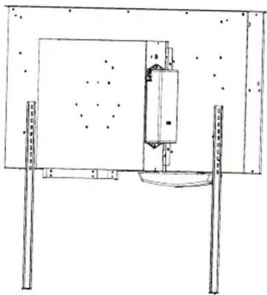
6
Now the oil cup is installed.
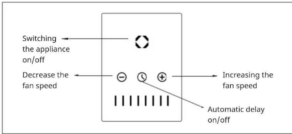
OPERATION
Raising/lowering the cooker bonnet
When pressing the pull-out button for 2 seconds, the cooker bonnet starts to lift and remains in the highest available position. Press the button again to lower the cooker bonnet again.
Note: Make sure that the core is not blocked or obstructed during retraction and extension. There is a risk of lifting a container (handle, etc.) and possibly spilling hot contents.
Set the line level
In operating mode, briefly press the or button to decrease or increase the speed by one level (from level 1 to 8). Press and hold the button to activate the booster function. After 5 minutes, the speed automatically changes to level 8.
Automatic delay
Press the button to activate a 5-minute delay. When the button starts flashing, the automatic delay is activated
CLEANING AND MAINTENANCE
Note: Disconnect the cooker bonnet from the power supply before carrying out maintenance or cleaning work by pulling out the appliance plug or completely unscrewing the circuit breaker of the domestic installation or the screw fuse of the domestic installation.
- The extractor hood must not be cleaned with a steam cleaner.
- Do not use cleaning agents containing alcohol to clean appliances with a matt black surface. These can lead to discolouration.
- Failure to observe the maintenance and cleaning instructions may result in a fire hazard due to grease deposits.
- The grease filters of your appliance must be cleaned or replaced regularly.
- Filters saturated with grease can quickly catch fire and also spread unpleasant odours.
- Grease filters clogged with dirt particles considerably impair the function of the appliance.
- When cleaning in the area of the controls, make absolutely sure that no water enters the electronics.
Special notes for devices with stainless steel housing
- For cleaning stainless steel surfaces, a commercially available, non-abrasive stainless steel cleaning agent should be used.
- To prevent rapid re-soiling of the surfaces, it is recommended to treat them with a stainless steel preservative.
- Apply the agent sparingly over the entire surface with a soft cloth.
- Never use stainless steel cleaning agent near the operating elements.
- When cleaning metal grease filters, take care not to damage the fabric.
- Frequent cleaning or the use of aggressive cleaning agents may cause colour changes on the metal surface. These do not affect the function of the filter and are no reason for complaint.
Changing the grease filter
- Change paper grease filters monthly.
- Change paper grease filters with alarm every two months or when the colour of the surface becomes visible through the mesh openings. This filter is coloured on one side; after installation, this colouring must no longer be visible through the mesh openings.
-
Foam grease filters must be soaked in warm soapy water for 1 to 2 hours once a month. Do not squeeze the grease filters and repeat the procedure if necessary. Replace the foam grease filter with a new one after a maximum of 5-6 washing cycles.
-
Metal grease filters do not need to be replaced when they are over-saturated, but washed once a month by hand or in the dishwasher (60^) . Allow the filter to dry thoroughly and carefully reinsert it in the cooker bonnet. Do not use alkaline dishwashing detergents (pH value above 7).
Activated carbon filter
a) Conventional activated carbon filters (usually round) cannot be washed or reused. With normal use and depending on the size, they should be replaced every 4 to 6 months. Follow the relevant instructions on the packaging.
b) Washable and reusable activated charcoal filters (usually square) should be cleaned once a month in the dishwasher using a commercial detergent and the intensive rinse programme (at the highest temperature). Washable and reusable activated charcoal filters absorb kitchen odours for a maximum of 3 years when cleaned monthly. After this period, the filter should be replaced with a new one.
- Washable and reusable activated charcoal filters should be washed separately to avoid deposits of food residues that can later cause unpleasant odours. After washing, the washable and reusable activated carbon filter must be reactivated. This is done by drying the cleaned filter in the oven at 100^ for 10 minutes. Read on the packaging whether your activated charcoal filter is washable and reusable. If there is no indication on the packaging, it is a conventional, non-washable activated charcoal filter.
- After each change or washing of a grease filter or charcoal filter, clean all exposed lower parts of the extractor bonnet with a mild grease solvent. For daily cleaning of the outer surfaces of the bonnet, use a soft cloth moistened with alcohol or a mild liquid cleaner. Never use an abrasive cleaner. There is a risk of fire if the instructions for cleaning the extractor bonnet and changing or cleaning the filters are not followed.
WARNING
Risk of fire! Always follow the instructions for cleaning the cooker bonnet and filters.
Lighting
This appliance has a built-in LED strip. This strip does not need to be replaced.
TROUBLESHOOTING
| Problem Potential cause | Solution | |
| The light turns on but the motor does not run. | The rotor blade of the fan is blocked. | Switch off the appliance and have it repaired by qualified personnel only. |
| The motor is broken. |
| The light is off and the motor does not run. | The light is broken. Have the plug is loose. Plug the | the light replaced. |
| The plug is loose. Plug the | power plug securely into the wall socket. |
| The housing vibrates. The | rotor blade of the fan is damaged. | Switch off the appliance and have it repaired by qualified personnel only. |
| The motor is not firmly seated. |
| The casing is loosely hanging. | Remove the appliance and make sure that the bracket is properly attached. |
| The air is not being properly extracted. | The distance between the cooker and the extractor hood is too far. | Reduce the distance to 65-75 cm. |
NOTES ON ENVIRONMENTAL PROTECTION
- Make sure there is sufficient air supply during cooking so that the cooker hood can work efficiently and with low operating noise.
- Adjust the fan speed to the amount of steam produced while cooking. Use the intensive mode only when necessary. The lower the fan speed, the less energy is consumed.
- If large amounts of steam are produced when cooking, select a higher fan speed in time. If the cooking steam has already spread throughout the kitchen, the cooker hood must be operated for longer.
- Switch off the cooker hood when it is no longer needed.
- Switch off the lighting when it is no longer needed.
- Clean the filter at regular intervals and replace it if necessary to increase the effectiveness of the ventilation system and prevent fire hazards.
- Always put the lid on when cooking to reduce cooking steam and condensation.
PRODUCT DATA SHEET
Measurement and calculation methods according to EN 61591:1997+A1:2006+A2:2011+A11:2014+A12:2015
| Item number | 10041402, 10046381, 10046382 |
| Description Symbol Value Unit | | | |
| Annual Energy Consumption AEC | hood | 37.0 kWh/Year | |
| Energy Efficiency class A+ | | | |
| Fluid Dynamic Efficiency FDE | hood | 32.9 | |
| Fluid Dynamic Efficiency class A | | | |
| Lighting Efficiency LE | hood | - Lux/W | |
| Lighting Efficiency class - | | | |
| Grease Filtering Efficiency GFE | hood | 68.5 % | |
| Grease Filtering Efficiency class D | | | |
| Air flow at minimum and maximum speed in normal use, intensive or boost excluded | | 243.3/495.2 m³/h | |
| Air flow at intensive or boost setting | | 708.3 m³/h | |
| Airborne acoustical A-weighted sound power emissions at minimum and maximum speed available in normal use | | 42/60 | dB |
| Airborne acoustical A-weighted sound power emissions at intensive or boost setting | | 66 | dB |
| Power consumption in off mode | Po | - | W |
| Power consumption in standby mode | Ps | 0.70 W | |
| Contact details | Chal-Tec GmbH, Wallstraße 16, 10179, Berlin, Germany |
Measurement and calculation methods according to EN 61591:1997+A1:2006+A2:2011+A11:2014+A12:2015
| Item number | 10041402, 10046381, 10046382 |
| Designation Symbol Value Unit | | | |
| Annual Energy Consumption AEC | hood | 37.0 kWh/year | |
| Time extension factor f 0.8 | | | |
| Fluid Dynamic Efficiency FDE | hood | 32.9 | |
| Energy Efficiency Index EEI | hood | 43.5 | |
| Measured air volume flow at the optimum level | QBEP | 374.5 m³/h | |
| Measured air pressure at the optimum level | PBEP | 401 Pa | |
| Maximum air flow Q | max | 495.2 m³/h | |
| Measured electrical input power at the optimum level | WBEP | 126.7 W | |
| Rated power of the lighting system | WL | - | W |
| Average illuminance of the lighting system on the cooking surface | Emiddle | -Lux | |
| Measured power consumption in standby mode | PS | 0.70 W | |
| Measured power consumption in off-mode | Po | - | W |
| Sound power level L | WA | 60 dB | |
| Contact details Chal-Tec GmbH, Walstraße 16, 10179 Berlin, Germany. |
DISPOSAL CONSIDERATIONS
If there is a legal regulation in your country regarding the disposal of electrical and electronic equipment, this symbol on the product or on the packaging indicates that this product must not be disposed of with household waste. Instead, it must be taken to a collection point for the recycling of electrical and electronic equipment. By disposing of this product in accordance with the regulations, you protect the environment and the health of those around you from negative consequences. For information on recycling and disposal of this product, contact your local government or household waste disposal service.
MANUFACTURER & IMPORTER (UK)
Manufacturer:
Chal-Tec GmbH, Wallstrasse 16, 10179 Berlin, Germany.
Importer for Great Britain:
Berlin Brands Group UK Limited
PO Box 42
272 Kensington High Street
London, W8 6ND
United Kingdom
Cher client, chere clientele,
FICHE DE DONNÉES PRODUIT
Berlin Brands Group UK Ltd
PO Box 42
272 Kensington High Street
London, W8 6ND
United Kingdom
Estimado cliente:
Berlin Brands Group UK Limited
PO Box 42
272 Kensington High Street
London, W8 6ND
Reino Unido
Gentile clientele,
PRODUTTORE IMPORTATORE (UK)
Produttore:
Chal-Tec GmbH, Wallstraße 16, 10179 Berlin, Germania.
Berlin Brands Group UK Limited
PO Box 42
272 Kensington High Street
London, W8 6ND
United Kingdom

KLARSTEIN