Y7N - Measuring equipment CHAUVIN ARNOUX - Free user manual and instructions
Find the device manual for free Y7N CHAUVIN ARNOUX in PDF.


User questions about Y7N CHAUVIN ARNOUX
0 question about this device. Answer the ones you know or ask your own.
Ask a new question about this device
Download the instructions for your Measuring equipment in PDF format for free! Find your manual Y7N - CHAUVIN ARNOUX and take your electronic device back in hand. On this page are published all the documents necessary for the use of your device. Y7N by CHAUVIN ARNOUX.
USER MANUAL Y7N CHAUVIN ARNOUX
natural_image
Line drawing of a soldering iron with a black cable, no text or symbols presentFRANÇAIS
ENGLISH
DEUTSCH
ITALIANO
- 70070 PARIS ESPANOL
Mode d'emploi
User's manual
Bedienungsanleitung
Libretto d'istruzioni Oedex 18 • FRANOE
line
| TEMPERATURE | HUMOITE | | ----------- | ------- | | -50°C | 85% | | -30°C | 85% | | -10°C | 85% | | 10°C | 85% | | 30°C | 75% | | 50°C | 85% | | 70°C | 60% | | 90°C | 60% |4.44. CONFORMITÉ AUX NORMES INTERNATIONALESCONFORMITÉ AUX NORMES I
Meaning of the symbol

Caution! Read the user's manual before using the instrument. In this manual, if the safety instructions prefixed with this symbol are not observed or followed, this will bring hazardous conditions for the operator or for the instrument and installation.
Thank you for purchasing a Y7N current clamp. To make the most of your instrument:
- read this user's manual carefully,
– observe the safety precautions.

SAFETY PRECAUTIONS

■ Do not use this instrument for measuring currents exceeding 700 A and limit the operating time from 500 A (see 4.3.1 Overloads).
■ Do not use on uninsulated conductors with a 600 V neutral-to-ground potential (see 4.4 Conformity to standards).
■ Do not expose to falling water.
- Keep the jaw faces perfectly clean (see 5.1 Cleaning).
CONTENTS
- Overview 14
- Description.... 14
- Operation 15
- Specifications 16
4.1 Reference conditions 16
4.2 Measurement range 16
4.3 Operating conditions and influences 17
4.4 Conformity to international standards 18
- Maintenance.... 19
5.1 Cleaning 19
5.2 Calibration 19
- Guarantee 20
6.1 Repair under or out guarantee 20
- Appendix 52
ORDERING REFERENCES
Oscilloscope Y7N current clamp P01.1200.75
1. OVERVIEW
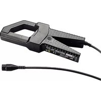
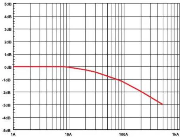
The scope Y7N current clamp, with an output-input ratio equal to 1 mV\~ / A\~, is designed for alternating current measurements in low- and medium-voltamper systems, from 1 A to 500 A\~ (up to 700 A\~ max., see chapter 4.3.1).
The frequency range is 5 Hz to 10 kHz.
The asymmetrically shaped jaws clamp around cables or busbars.
The Y7N connects to any scope via a BNC cord.
It features dual or reinforced insulation and conforms to international standards, such as IEC 1010-2-032 « Current clamps » (see chapter 4.4).
2. DESCRIPTION
(See drawing on page 56)
Overall dimensions: 195 x 66 x 34 mm.
Weight: 420 g.
① Jaw opening: 195 x 66 x 34 mm.
Open jaw height: 96 mm
② 4 centring marks
Max clamping capacity: ∅ 30 mm cable and 63 x 5 mm busbar
③ « I » arrow indicating the direction of current flow. The current is considered to flow in the positive direction when flowing from the « current producer » to the « current consumer ». This orientation of the current clamp is required during a power measurement (current measured concurrently with voltage).
④ Cable length: 2 m
⑤ Output via an insulated 50 Ω BNC plug.
3. OPERATION

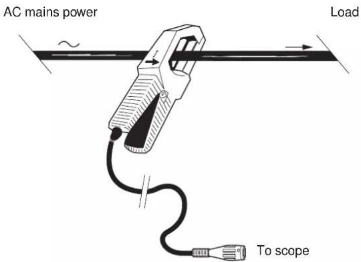
Although there is no special hazard, do not clamp a conductor before connecting the current clamp to the scope. Similarly, do not disconnect the current clamp from the scope when the clamp is closed around a cable.
■ Open the jaws and clamp the cable carrying the current to be measured. Centre the cable using the marks. Observe the direction of the I arrow if required by the application.
To read the measured current, apply the appropriate reading coefficient. The current clamp delivers 1 mV\~ for a current of 1 A\~.
text_image
AC mains power Load To scope
From 500 A to 700 A, limit the current clamp operating time: 10 minutes on and 30 minutes off.
4. SPECIFICATIONS
4.1 REFERENCE CONDITIONS
■ Temperature: 18 ° to 28 °C
■ Relative humidity: 0 to 85 % RH
■ Conductor centred in the jaws
■ Sinusoidal current: 45 to 65 Hz
■ No direct current
■ Scope impedance: 1 MΩ - 47 pF
■ Direct-current magnetic field: earth's magnetic field (< 40 A/m)
■ External conductor proximity: no direct or alternating current
■ Intrinsic error or phase difference
NOTE: Linear interpolation between each value
(see also the graphs in chapter 7. APPENDIX)
| Current to be mesured | in A~ | 1 - 20 A | 20 - 100 A | 100 - 500 A |
| in % of In | .2% - 4% | 4% - 20% | 20% - 100% | |
| Intrinsic error ^(1) | 5% + .3 A | 5% | 2% | |
| Phase difference | (2) | 3° | 1° | |
(1) In ± % of the output
(2) Unspecified
4.2 MEASUREMENT RANGE
| Current range 1 ... 700 A ~ | (1) |
| Output-to-input ratio 1 mV~/A ~ | |
| Frequency range 5 Hz ... 10 kHz | (2) |
(1) See 4.3.1 Overloads
(2) See graphs in 7 - APPENDIX
■ Nominal current (In): 500 A\~
■ dV/dt: typical .24 mV/μs
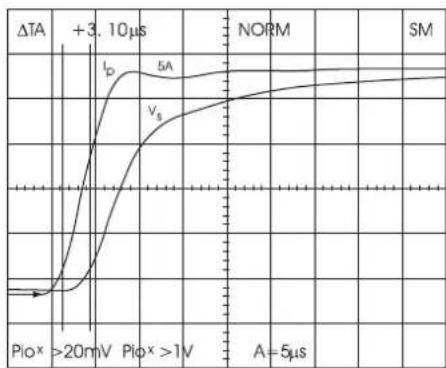
■ Rise time at 5 A: typical 18 μs
■ Fall time at 5 A: typical 23 μs
■ Delay at 5 A: typical 3.1 μs

4.3 OPERATING CONDITIONS AND INFLUENCES
The current clamp must be used under the following conditions to meet the user safety and measuring performance requirements.
4.3.1 Overloads
■ Limit the operating time above 500 A\~
| Curant | I ≤ 500 A | 500 A ≤ I ≤ 700 A |
| Working | Continuous operation | 10 minutes on30 minutes off |
■ Peak current maximum: 1200 A
4.3.2 Influence of frequency
■ Values to be added to the reference conditions.
NOTE: See also graphs in 7-APPENDIX.
| Frequency | 5 to 10 Hz | 10 to 20 Hz | 20 to 45 Hz | 65 Hz to 3 kHz | 3 to 6 kHz | 6 to 10 kHz |
| 1 A to 200 A 15 % | ||||||
| >200 A (1) | ||||||
| 1 A to 200 A 5 % | ||||||
| 200 A to 300 A 15 % | ||||||
| >400 A - 3 dB | ||||||
| 1 A to 500 A 5 % | ||||||
| 1 A to 50 A 5 % + .4 A | ||||||
| 50 A to 200 A 5 % | ||||||
| >200 A (1) | ||||||
| 1 A to 100 A 15 % + .4 A | ||||||
| >100 A (1) | ||||||
| 1 A to 50 A - 3 dB | ||||||
| >50 A (1) |
NOTE: Error in % of reading
(1) Unspecified
■ Derating: to calculate the maximum current (A) in continuous operation, depending on frequency (F in kHz), use the formula: 500 (A) x 2/F (kHz).
4.3.3 Environmental conditions4.3.3 Environmental conditions
■ Indoor use
■ Altitude: 2000 m
■ Transportation altitude: 12000 m
■ Temperature influence: < .15% / 10°C
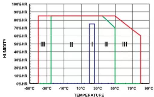
■ Climatic conditions
line
| TEMPERATURE | HUMIDITY | | ----------- | -------- | | -50°C | 50% | | -30°C | 85% | | -10°C | 50% | | 10°C | 50% | | 30°C | 75% | | 50°C | 85% | | 70°C | 60% | | 90°C | 60% |I - Reference domain
II - Operation domain
III - Storage domain
4.4 CONFORMITY TO INTERNATIONAL STANDARDS
4.4.1 Electrical safety (in accordance with IEC 1010-2-032)4.4.1 Electrical safety (in accordance with IEC
- Dual insulation ☐
- Pollution degree 2
- Installation category III with operating voltage: 600 V
- Installation category IV with operating voltage: 300 V
4.4.2 Electromagnetic compatibility 4.4.2 Electromagnetic compatibility
■ Emission: class B (i.a.w EN 50081-1)
■ Immunity (i.a.w EN 50082-2)
- Electrostatic discharge (i.a.w IEC 1000-4-2): 4 kV in contact - level 2 - capability criterion B 8 kV in air - level 3 - capability criterion B
- Radiated electromagnetic energy (i.a.w IEC 1000-4-3): 10 V/m - level 3 - capability criterion A
- Short-duration transients (i.a.w IEC 1000-4-4): 2 kV - level 3 - capability criterion B
- Line frequency magnetic field (i.a.w IEC 1000-4-8): 30 A/m - level 4 - capability criterion A
4.4.3 Mechanical protection4.4.3 Mechanical protection
- Tightness: protection level IP20 (i.a.w IEC 529) with jaws closed
- Free fall: 1.5 m (i.a.w IEC 68-2-32)
- Shocks: 100 g (i.a.w IEC 68-2-27)
- Vibrations: .15 mm - 10/55/10 Hz (i.a.w IEC 68-2-6)
4.4.4 Flammability rating 4.4.4 Flammability rating
- VO (i.a.w UL 94)
5. MAINTENANCE

For servicing these units, only use the specified spare parts. The manufacturer will not be held as responsible for any accident resulting from a repair made outside its after-sales service or accredited repair centers.
5.1 CLEANING

The clamp must not enclose a cable and must be disconnected from the measuring device. Do not subject the clamp to running water.
- Keep the jaw faces perfectly clean. Remove dust with a soft dry cloth. Now and then, clean the jaw faces with a lightly oiled solft cloth.
■ Clean the case with a cloth slightly moistened with soapy water. Rinse with a dry cloth. Then dry quickly with a cloth or in a hot air stream (80°C max.).
5.2 CALIBRATION

As any other measuring or test instrument, your instrument must be regularly checked.
For a daily use < 4 hours, we recommend that an annual calibration be carried out. When the instrument is used continuously every day, we recommend that a calibration be carried out every 6 months.
For calibration and repair of your instruments, please contact our COFRAC-BNM accredited laboratories:
or CHAUVIN ARNOUX subsidiary in your country.
6. GUARANTEE
Unless notified to the contrary, our instruments are guaranteed from any manufacturing defect or material defect. They do not bear the specification known as the safety specification. Our guarantee, which may not under any circumstances, exceed the amount of the invoiced price, goes no further than the repair of our faulty instrument, carriage paid, to our workshops. It is applicable for normal use of our instruments, and does not apply to damage or destruction caused, notably by error in mounting, mechanical accident, faulty maintenance, defective use, overload or excess voltage. Our responsibility being strictly limited to the pure and simple replacement of the faulty parts of our equipment, the buyer expressly renounces any attempt to find us responsible for damages or losses caused directly or indirectly.
Our guarantee is applicable for twelve (12) months after the date on which the equipment is made available. The repair, modification or replacement of a part during the guarantee period will not result in this guarantee being extended.
6.1 REPAIRS UNDER OR OUT OF GUARANTEE
For any repair whether under guarantee or not, please return the unit to your distributor.
line
| TEMPERATUR | REL. FEUCHTE | | ---------- | ------------ | | -50°C | 0% | | -30°C | 85% | | -10°C | 85% | | 10°C | 50% | | 30°C | 75% | | 50°C | 85% | | 70°C | 70% | | 90°C | 60% |line
| TEMPERATURA | UMDITA | | ----------- | ------ | | -50°C | 85% | | -30°C | 85% | | -10°C | 85% | | 10°C | 85% | | 30°C | 75% | | 50°C | 85% | | 70°C | 60% | | 90°C | 60% |line
| TEMPERATURA | HUMEDAD | | ----------- | ------- | | -50°C | 0% | | -30°C | 85% | | -10°C | 85% | | 10°C | 85% | | 30°C | 75% | | 50°C | 85% | | 70°C | 60% | | 90°C | 60% |■ Typical error (in%) versus frequency (Hz) - Current A
■ Typical phase difference (°) versus frequency (Hz) - Current A
line
| Frequency | Phase Angle (°) | | :--- | :--- | | 50 | 14 | | 100 | 12 | | 200 | 10 | | 300 | 8 | | 500 | 6 | | 1 kHz | -2 | | 1 kHz | -4 | | 1 kHz | -6 | | 1 kHz | -8 | | 1 kHz | -10 | | 1 kHz | -12 | | 1 kHz | -14 | | 1 kHz | -16 | | 1 kHz | -18 | | 1 kHz | -20 | | 1 kHz | -22 | | 10 kHz | -22 | | 10 kHz | -24 | | 10 kHz | -26 | | 10 kHz | -28 | | 10 kHz | -30 | | 10 kHz | -32 | | 10 kHz | -34 | | 10 kHz | -36 | | 10 kHz | -38 | | 10 kHz | -40 | | 10 kHz | -42 | | 10 kHz | -44 | | 10 kHz | -46 | | 10 kHz | -48 | | 10 kHz | -50 | | 10 kHz | -52 | | 10 kHz | -54 | | 10 kHz | -56 | | 10 kHz | -58 | | 10 kHz | -60 | | 10 kHz | -62 | | 10 kHz | -64 | | 10 kHz | -66 | | 10 kHz | -68 | | 10 kHz | -70 | | 10 kHz | -72 | | 10 kHz | -74 | | 10 kHz | -76 | | 10 kHz | -78 | | 10 kHz | -80 | | 10 kHz | -82 | | 10 kHz | -84 | | 10 kHz | -86 | | 10 kHz | -88 | | 10 kHz | -90 | | 10 kHz | -92 | | 10 kHz | -94 | | 10 kHz | -96 | | 10 kHz | -98 | | 10 kHz | -100 | | 10 kHz | -102 | | 10 kHz | -104 | | 10 kHz | -106 | | 10 kHz | -108 | | 10 kHz | -110 | | 10 kHz | -112 | | 10 kHz | -114 | | 10 kHz | -116 | | 10 kHz | -118 | | 10 kHz | -120 | | 10 kHz | -122 | | 10 kHz | -124 | | 10 kHz | -126 | | 10 kHz | -128 | | 10 kHz | -130 | | 10 kHz | -132 | | 10 kHz | -134 | | 10 kHz | -136 | | 10 kHz | -138 | | 10 kHz | -140 | | 10 kHz | -142 | | 10 kHz | -144 | | 10 kHz | -146 | | 10 kHz | -148 | | 10 kHz | -150 | | 10 kHz | -152 | | 10 kHz | -154 | | 10 kHz | -156 | | 10 kHz | -158 | | 10 kHz | -160 | | 10 kHz | -162 | | 10 kHz | -164 | | 10 kHz | -166 | | 10 kHz | -168 | | 10 kHz | -170 | | 10 kHz | -172 | | 10 kHz | -174 | | 10 kHz | -176 | | 10 kHz | -178 | | 10 kHz | -180 | | 10 kHz | -182 | | 10 kHz | -184 | | 10 kHz | -186 | | 10 kHz | -188 | | 10 kHz | -190 | | 10 kHz | -192 | | 10 kHz | -194 | | 10 kHz | -196 | | 10 kHz | -198 | | 10 kHz | -200 | |■ Influence d'un courant continu (A) sur la mesure
■ Influence of direct current (A) on measurement
■ Einfluß eines überlagerten Gleichstroms auf die Messung
■ Influenza di una corrente continua (A) sulla misura
■ Influencia de una corrinte continua (A) sobre la medida
line
| x | y | | ---- | ----- | | 1A | 0 dB | | 10A | 0 dB | | 100A | -1 dB | | 1kA | -3.5 dB |■ Réponse à un échelon
■ Response for one step
■ Verhalten auf Anstiegsflanke
■ Risposta a 1 gradino
■ Respuesta impulsional a un escalón
line
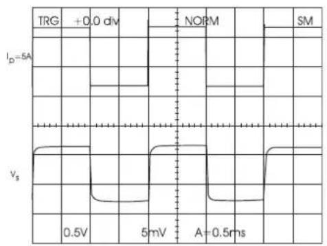
| Condition | Current (I_p) | Voltage (V_s) | | --------- | ------------- | ------------- | | ΔTA | +3.10μs | - | | NORM | - | - | | SM | - | - |■ Réponse impulsionnelle
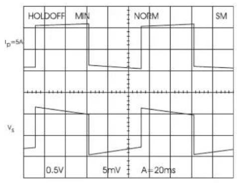
■ Pulse response
■ Verhalten bei Rechtecksignalen
■ Rispota impulsiva
■ Respuesta impulsional
10 Hz 50 Hz
line
| Time (ms) | Voltm | |-----------|-------| | 0 | 0.5V | | 5 | 5mV | | 10 | 0.5V | | 15 | 5mV | | 20 | 0.5V |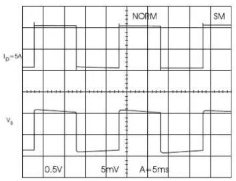
500 Hz 4 kHz
line
| Voltage | Current | | ------- | ------- | | 0.5V | 0.0 | | 5mV | 0.0 | | A | 0.5ms |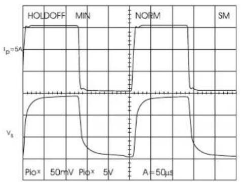
line
| Time (μs) | I_p=5A | v_s | |-----------|--------|-----| | 0 | 5A | 0 | | 5 | 5A | 0 | | 10 | 5A | 0 | | 15 | 5A | 0 | | 20 | 5A | 0 | | 25 | 5A | 0 | | 30 | 5A | 0 | | 35 | 5A | 0 | | 40 | 5A | 0 | | 45 | 5A | 0 | | 50 | 5A | 0 | | 55 | 5A | 0 | | 60 | 5A | 0 | | 65 | 5A | 0 | | 70 | 5A | 0 | | 75 | 5A | 0 | | 80 | 5A | 0 | | 85 | 5A | 0 | | 90 | 5A | 0 | | 95 | 5A | 0 | | 100 | 5A | 0 | | 105 | 5A | 0 | | 110 | 5A | 0 | | 115 | 5A | 0 | | 120 | 5A | 0 | | 125 | 5A | 0 | | 130 | 5A | 0 | | 135 | 5A | 0 | | 140 | 5A | 0 | | 145 | 5A | 0 | | 150 | 5A | 0 | | 155 | 5A | 0 | | 160 | 5A | 0 | | 165 | 5A | 0 | | 170 | 5A | 0 | | 175 | 5A | 0 | | 180 | 5A | 0 | | 185 | 5A | 0 | | 190 | 5A | 0 | | 195 | 5A | 0 | | 200 | 5A | 0 | | 205 | 5A | 0 | | 210 | 5A | 0 | | 215 | 5A | 0 | | 220 | 5A | 0 | | 225 | 5A | 0 | | 230 | 5A | 0 | | 235 | 5A | 0 | | 240 | 5A | 0 | | 245 | 5A | 0 | | 250 | 5A | 0 | | 255 | 5A | 0 | | 260 | 5A | 0 | | 265 | 5A | 0 | | 270 | 5A | 0 | | 275 | 5A | 0 | | 280 | 5A | 0 | | 285 | 5A | 0 | | 290 | 5A | 0 | | 295 | 5A | 0 | | 300 | 5A | 0 | | | | +∞ (not labeled) for all panels. The output voltage is calculated based on the input current (p_i × p_o × p_i × p_o × p_i × p_o × p_i × p_o × p_i × p_o × p_i × p_o × p_i × p_o × p_i × p_o × p_i × p_o × p_i × p_o × p_i × p_o × p_i × p_o × p_i × p_o × p_i × p_o × p_i × p_o × p_i × p_o × p_i × p_o × p_i × p_c V_s V_s V_s V_s V_s V_s V_s V_s V_s V_s V_s V_s V_s V_s V_s V_s V_s V_s V_s V_s V_s V_s V_s V_s V_s V_s V_s V_s V_s V_s V_s V_s V_s V_s = -∞ (not labeled) for the output voltage.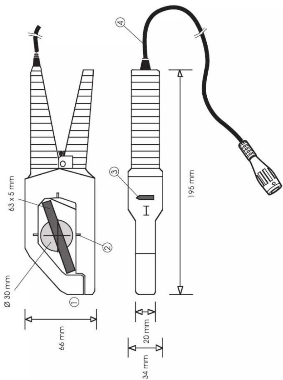
text_image
195 mm 34 mm 20 mm 66 mm Ø 30 mm 63 x 5 mm ① ② ③ ④NOTES / NOTIZEN / APPUNTI / NOTASNOTES / NOTIZEN / APPUNTI / No
NOTES / NOTIZEN / APPUNTI / NOTASNOTES / NOTIZEN / APPUNTI / NC