C.A 6511 - Measuring equipment CHAUVIN ARNOUX - Free user manual and instructions
Find the device manual for free C.A 6511 CHAUVIN ARNOUX in PDF.


User questions about C.A 6511 CHAUVIN ARNOUX
0 question about this device. Answer the ones you know or ask your own.
Ask a new question about this device
Download the instructions for your Measuring equipment in PDF format for free! Find your manual C.A 6511 - CHAUVIN ARNOUX and take your electronic device back in hand. On this page are published all the documents necessary for the use of your device. C.A 6511 by CHAUVIN ARNOUX.
USER MANUAL C.A 6511 CHAUVIN ARNOUX
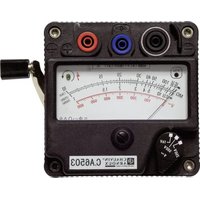
Thank you for purchasing a C.A 6511 or C.A 6513 meghommeter and we thank you for your trust.
For best results from your instrument:
■ read this user manual carefully,
■ comply with the precautions for use.

WARNING, risk of DANGER! The operator should refer to this user's manual whenever this danger symbol appears.

Equipment protected by double insulation.

Earth. Battery. Fuse.


The CE marking indicates compliance with the European Low Voltage Directive (2014/35/EU), Electromagnetic Compatibility Directive (2014/30/EU), and Restriction of Hazardous Substances Directive (RoHS, 2011/65/EU and 2015/863/EU).

The UKCA marking certifies that the product is compliant with the requirements that apply in the United Kingdom, in particular as regards Low-Voltage Safety, Electromagnetic Compatibility, and the Restriction of Hazardous Substances.

The rubbish bin with a line through it indicates that, in the European Union, the product must undergo selective disposal in compliance with Directive WEEE 2012/19/EU. This equipment must not be treated as household waste.
Definitions of the measurement categories
■ Measurement category IV corresponds to measurements taken at the source of low-voltage installations. Example: power feeders, meters and protection devices.
■ Measurement category III corresponds to measurements on building installations. Example: distribution panel, circuit-breakers, machines or fixed industrial devices.
■ Measurement category II corresponds to measurements taken on circuits directly connected to low-voltage installations.
Example: power supply to domestic electrical appliances and portable tools.
CONTENTS
1. FIRST USE....16
1.1. Delivery condition 16
1.2. Spare parts....17
1.3. Inserting the batteries....17
2. PRESENTATION 18
2.1.C.A 6511 18
2.2.C.A 6513 19
3. USE....19
3.1. Precautions for use.... 19
3.2.Battery test 20
3.3. Insulation and voltage measurement....20
3.4. Continuity measurement....20
3.5. Resistance measurement (C.A 6513)....21
4. TECHNICAL SPECIFICATIONS....21
4.1. Reference condition....21
4.2. Electrical specifications ...... 21
4.3. Variations in the domain of use 22
4.4. Power supply 22
4.5.Environmental Conditions 23
4.6. Mechanical characteristics 23
4.7. Electrical safety 23
4.8.Conformity to international standards....24
4.9. Electromagnetic compatibility 24
5. MAINTENANCE....24
5.1. Cleaning 24
5.2. Protecting sheath....24
5.3. Replacement of the batteries or the fuse....24
6. WARRANTY 25
This device is compliant with safety standard IEC/EN 61010-2-034 or BS EN 61010-2-034 and the leads are compliant with IEC/EN 61010-031 or BS EN 61010-031 for voltages up to 600 V in category III. Failure to observe the safety instructions may result in electric shock, fire, explosion, or destruction of the instrument and of the installations.
■ The operator and/or the responsible authority must carefully read and clearly understand the various precautions to be taken in use. Sound knowledge and a keen awareness of electrical hazards are essential when using this instrument..
■ Do not use the instrument on networks of which the voltage or category exceeds those mentioned..
■ Never exceed the protection limits stated in the specifications.
- Observe the conditions of use, namely the temperature, the relative humidity, the altitude, the degree of pollution, and the place of use.
■ Do not use the instrument if it seems to be damaged, incomplete, or poorly closed.
■ Before each use, check the condition of the insulation on the leads, housing, and accessories. Any item of which the insulation is deteriorated (even partially) must be set aside for repair or scrapping.
■ Use only the leads and accessories supplied. Using leads (or accessories) of a lower voltage or category reduces the voltage or category of the combined instrument + leads (or accessories) to that of the leads (or accessories).
■ Use personal protection equipment systematically.
■ When handling test probes and crocodile clips, keep your fingers behind the physical guard.
■ All troubleshooting and metrological checks must be performed by competent and accredited personnel.
1. FIRST USE
1.1. DELIVERY CONDITION
The C.A 6511 and C.A 6513 megohmmeters are delivered in a cardboard box with :
■ two safety leads black and red,
■ one red probe tip,
■ one black crocodile clip,
■ one protecting sheath fitted on the instrument,
■ four AA or LR6 batteries,
■ one spare fuse,
■ one user manual in 5 languages,
■ one multilingual safety sheet.,
■ one verification certificate.
1.2. SPARE PARTS
■ Protecting sheath
■ Set of 10 fuses 6,3 x 32 1,6A 660V HPC
■ Set of 4 LR6 or AA batteries.
For the accessories and spares, consult our web site:
www.chauvin-arnoux.com
1.3. INSERTING THE BATTERIES
Check that no terminals are connected and that the switch is in the OFF position before opening the instrument. For safety, the instrument can only be opened if the leads are disconnected from the terminals.
■ Remove the protecting sheath.
■ Turn the instrument over.
■ Unscrew the captive screws using a screwdriver.
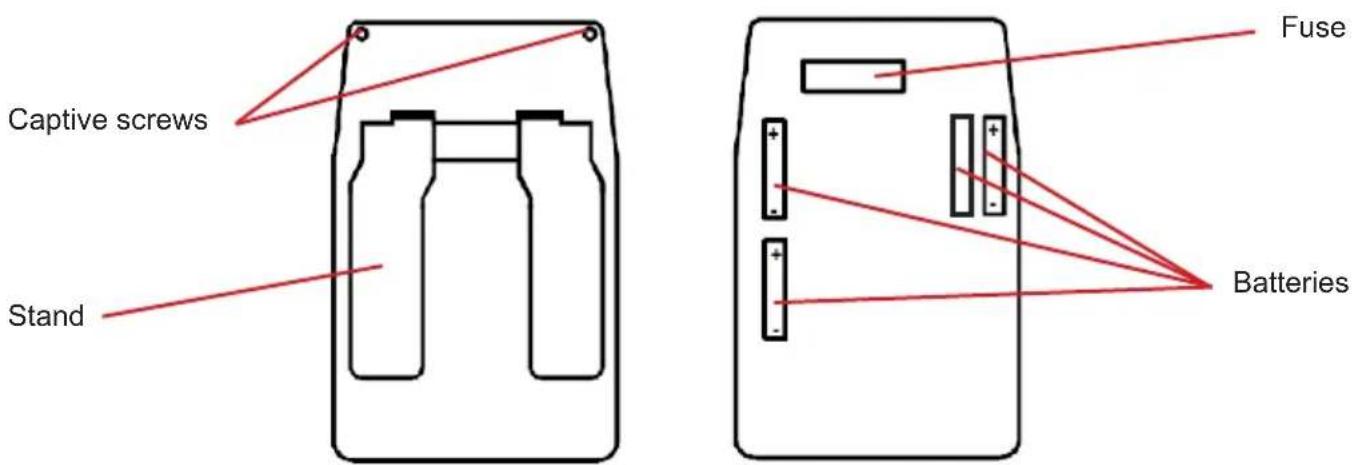
text_image
Captive screws Stand Fuse Batteries■ Withdraw the back of the case.
■ Insert the batteries in the battery compartment, paying attention to the polarity.

Do not press the yellow button when the instrument is open. There is a risk of accidental contact if the instrument is not resting on a flat surface while the batteries or fuse are being inserted or replaced.
■ Close the back of the case; make sure that it is completely and correctly closed.
■ Tighten the screws.
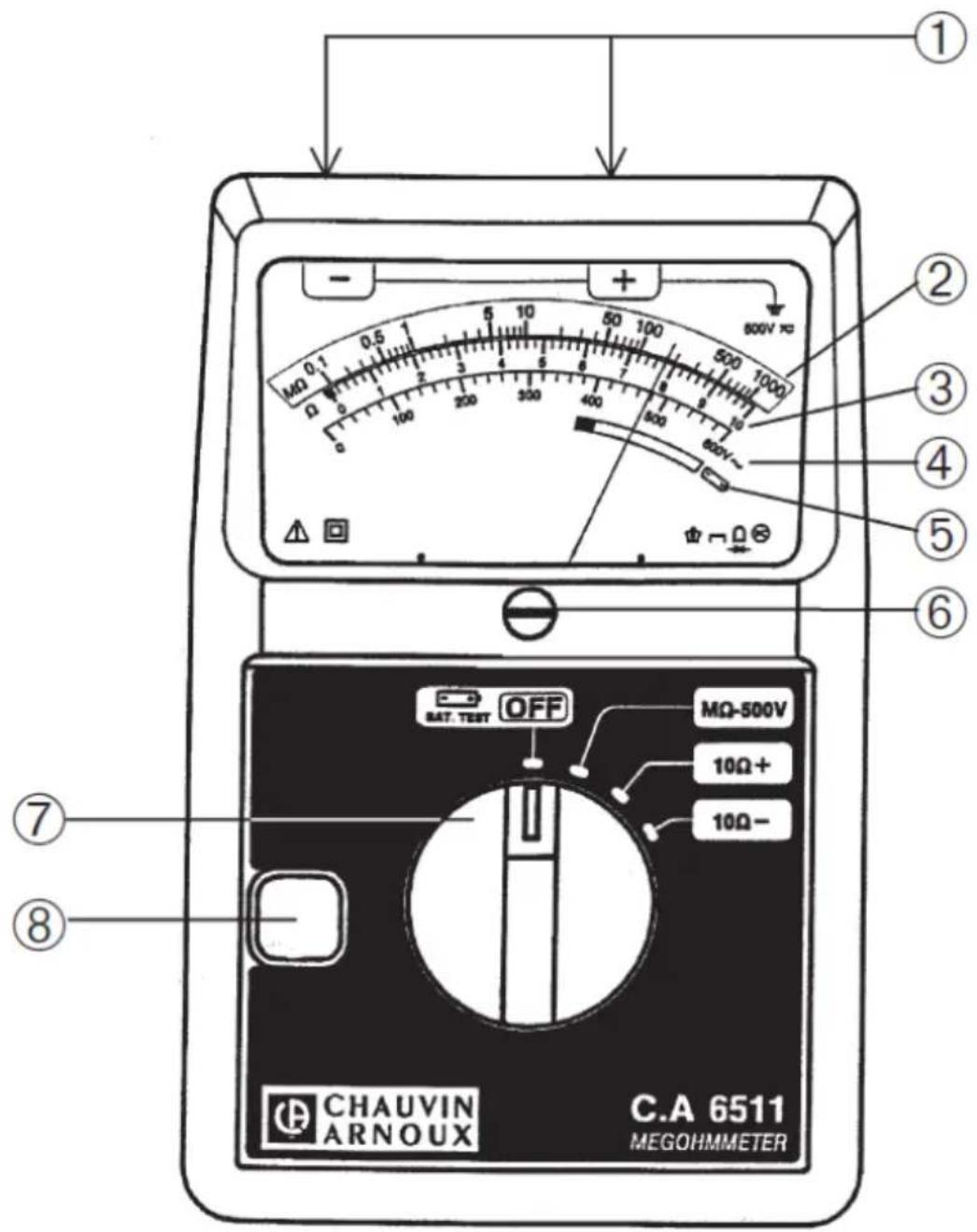
2.1. C.A 6511
text_image
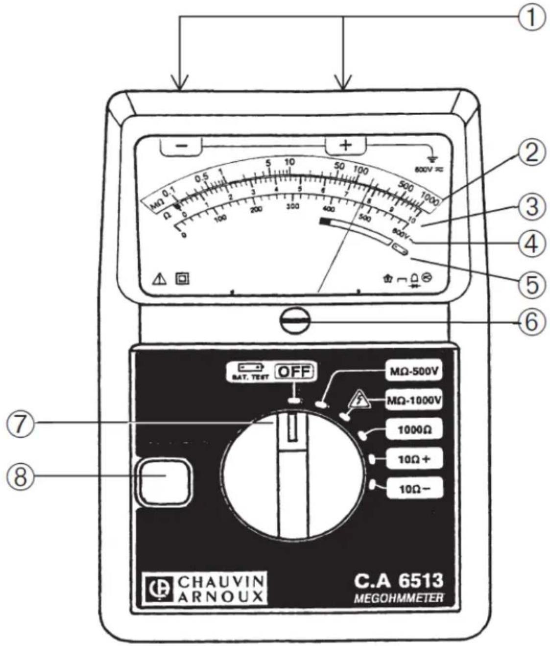
① ② ③ ④ ⑤ ⑥ ⑦ ⑧ CHAUVIN ARNOUX C.A 6511 MEGOHMMETER① Measurement terminals
② Log scale on yellow background from 0.1 to 1000 MΩ for insulation measurement
③ Linear scale from 0 to 10 Ω for continuity measurement and resistance measurement (C.A 6513)
④ Linear scale from 0 to 600 Vac for voltage measurement
⑤ Red / green scale for battery test
⑥ Screw to set mechanical zero
⑦ Rotary switch of 4 positions for the C.A 6511 and 6 positions for the C.A 6513.
⑧ Yellow button
2.2. C.A 6513
text_image
① ② ③ ④ ⑤ ⑥ ⑦ ⑧ CHAUVIN ARNOUX C.A 6513 MEGOHMMETER3. USE
3.1. PRECAUTIONS FOR USE
At rest, the needle must indicate 0 on the voltmeter scale. If not, adjust it by means of the mechanical zero set screw.
■ Position the switch in the OFF position when the instrument is not used..
3.2. BATTERY TEST
Before starting a measurement campaign, make sure that the batteries powering the instrument are sufficiently charged. Place the switch in the OFF position, press the yellow button, and check the battery status on the galvanometer scale
■ if the needle is in the green zone, the batteries are sufficiently charged,
■ if the needle is in the red zone, all four batteries need changing.
3.3. INSULATION AND VOLTAGE MEASUREMENT
Once you have ensured that the batteries are sufficiently charged (see § 3.1), you can take insulation measurements.
■ Connect the instrument to the installation to be inspected using the accessories supplied (leads, probe tip and crocodile clip). It is preferable for the + terminal to be earthed.
■ Use the switch to select an insulation measurement position: 500 V for the C.A 6511, 500 or 1000V for the C.A 6513.
At this point, the device automatically switches to AC voltmeter mode. It measures the voltage between the + and - terminals.
■ If it indicates no voltage, the insulation measurement can be taken.
If it indicates the presence of voltage on the circuit to be measured, you should not take an insulation measurement. Find the source of the voltage and remove it.
■ Start the insulation measurement by pressing the yellow button. The instrument generates a high voltage between the + and - terminals. The reading is taken directly on the yellow logarithmic scale from 0.1 to 1000 MΩ. As soon as the button is released, the device returns to voltage measurement. The high voltage present on the device under test is discharged via the leads in the instrument. The instrument must therefore be left plugged in for a few seconds once the measurement is complete (measurement returns to 0 V).
3.4. CONTINUITY MEASUREMENT
■ After connecting the instrument to the installation to be tested, check that there is no voltage (see § 3.3).
■ Then set the switch to the +10 Ω position. The measurement will be taken automatically without having to press the yellow button. Read the value on the white scale 0 to 10 Ω.
■ Then set the switch to the -10 Ω position and make sure that the pointer on the device indicates the same continuity value.
■ If this second value is different from the previous one, take the average:
$$ R \text { continuity } = \frac {R _ {+ 1 0 \Omega} + R _ {- 1 0 \Omega}}{2} $$
For a more accurate continuity measurement, measure the resistance of the leads by short-circuiting them. Then subtract this value from the measured resistances.
Notes:
■ To save battery power, disconnect the leads once the continuity measurement is complete.
■ If the instrument is not connected, or connected incorrectly, the needle will move to the right.
3.5. RESISTANCE MEASUREMENT (C.A 6513)
■ After connecting the instrument to the installation to be tested, check that there is no voltage (see § 3.3).
■ Set the switch to the 1000 Ω position. The measurement will be taken automatically without having to press the yellow button.
- Read the value on the white scale 0 to 10 Ω, applying a x100 coefficient.
Notes:
■ To save battery power, disconnect the leads once the resistance measurement is complete.
■ If the instrument is not connected, or connected incorrectly, the needle will move to the right.
4. TECHNICAL SPECIFICATIONS
4.1. REFERENCE CONDITION
| Quantity of influence Reference values | |
| Temperature 23 ± 5 °C | |
| Relative humidity 45 to 55 %RH | |
| Supply voltage 5.5 ± 0.2 V | |
| Frequency 50 or 60 Hz | |
| Electric field ≤ 1 V/m | |
| Magnetic field < 40 A/m | |
| Position Horizontal ± 5° | |
The intrinsic uncertainty is the error defined under the reference conditions.
4.2. ELECTRICAL SPECIFICATIONS
4.2.1. INSULATION MEASUREMENT
Specified measurement range: 0.1 to 1000 MΩ
Intrinsic uncertainty: 5% of the measurement
| Range 500 V 1 000 V (C.A) | 6513) | |
| No-load voltage | 600 V 1 200 V | |
| Test current | ≥ 1 mA for R ≤ 500 kΩ | ≥ 1 mA for R ≤ 1 MΩ |
| Short-circuit current | ≤ 6 mA | ≤ 6 mA |
The discharge time, i.e. the time it takes for the voltage present at the terminals to decrease by 90% of its value once the yellow button is released, is 1 s/ F.
4.2.2. CONTINUITY MEASUREMENT
Specified measurement range: 0 to 10 Ω with reversal of the measurement current
Scale : 0 to 10 Ω
Intrinsic uncertainty: 3% of end of scale
Short-circuit current: ≥ 200 mA
No-load voltage: 4,5 V ≤ V ≤ 6,5 V
4.2.3. RESISTANCE MEASUREMENT (C.A 6513)
Specified measurement range: 0 to 1000 Ω
Scale : 0 to 1000 Ω
Intrinsic uncertainty: 3% of end of scale
Short-circuit current: ≥ 2 mA
No-load voltage: 4,5 V ≤ V ≤ 6,5 V
4.2.4. VOLTAGE MEASUREMENT
Specified measurement range: 0 to 600 VAC
Scale : 0 to 600 V
Intrinsic uncertainty: 3% of end of scale
Input impedance: 300 kΩ
4.3. VARIATIONS IN THE DOMAIN OF USE
| Influence quantity Range of influence | Error in % of measurement | |
| Typical Maximum | ||
| Operating position | 0 + 90°0 -90° | - - ≤ 5% |
| Temperature -10 to + 55 °C | 3% / 10°C 3% / 10°C | |
| Relative humidity 10 to 80%RH | 2 | 5 % 10 % |
| Supply voltage 4,5 to 6,5 V 0,1 % 0,2% | ||
| Frequency (on voltage measurement) | 45 to 400 Hz - ≤ 0 | 1% |
| Electromagnetic field | 0 to 400 A/m3 | - |
1: For insulation measurements, this is % of the measurement. For other measurements, it is % of the end of scale.
2: For all measurements and insulation measurements up to 100 MΩ.
3: The magnetic fields considered are fields of stable amplitude and direction, and frequency between 0 and 60 Hz.
4.4. POWER SUPPLY
The instrument is powered by 4 alkaline batteries 1.5V type LR6 or AA.
The voltage range ensuring correct operation is from 4.5V to 6.5V.
Battery mass: about 4 x 26 g.
Consumption is approximately:
■ 300 mA for R = 0,5 MΩ on the MΩ 500 V range
■ 600 mA for R = 1 MΩ on the MΩ 1000 V range (C.A 6513)
■ 200 mA on continuity on the +10 Ω and -10 Ω ranges
■ 10 mA on ohmmeter on the 1000 Ω range (C.A 6513)
The average autonomy is:
■ 1000 insulation measurements of 10 s on the MΩ 500 V range for R = 500 kΩ,
■ 200 insulation measurements of 10 s on the MΩ 1000 V range for R = 1 MΩ (C.A 6513).
■ 1500 continuity measurements of 10 s on the 10 Ω range.
4.5. ENVIRONMENTAL CONDITIONS
line
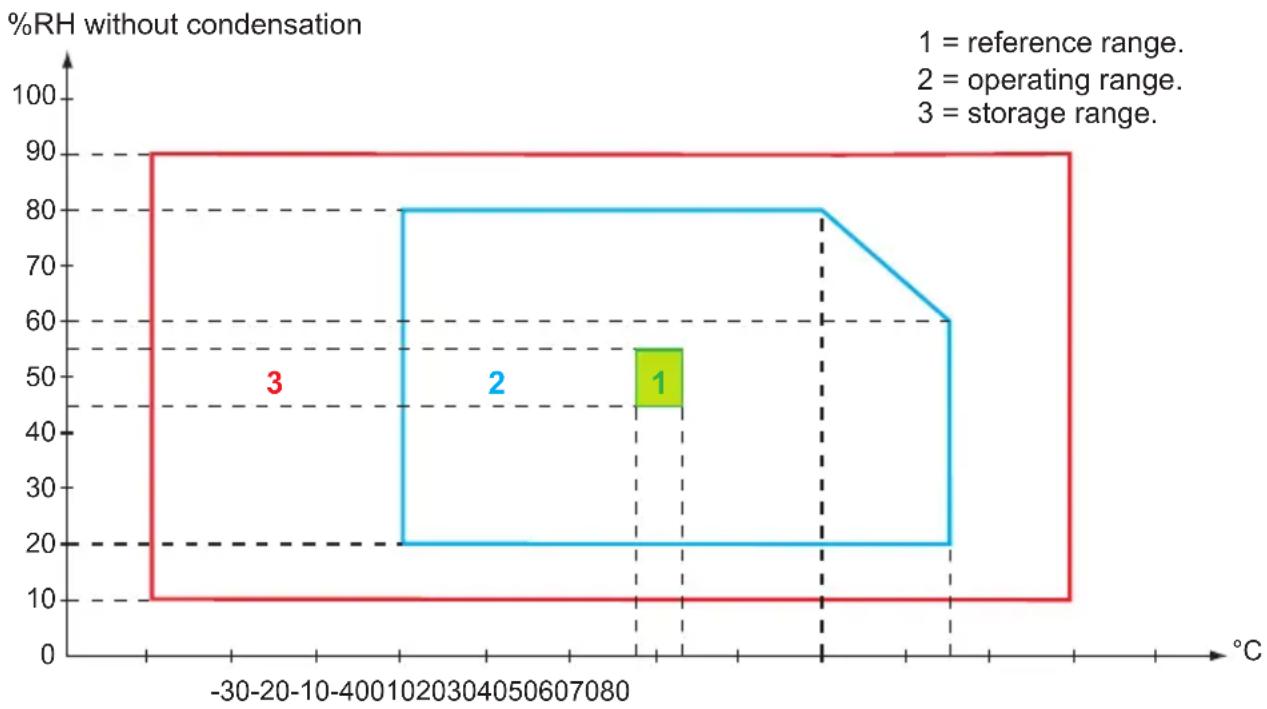
| Temperature Range | %RH without condensation | | ----------------- | ------------------------ | | -30-20-10-400 | 90 | | 1020-30-400 | 80 | | 405-60-70-80 | 80 | | 70-90 | 60 |Indoor use.
Pollution degree: 2
Altitude : < 2,000 m
4.6. MECHANICAL CHARACTERISTICS
Dimensions (L x W x H) 167 x 106 x 55 mm
Mass approximately 650 g (with the sheath and the batteries)
4.7. ELECTRICAL SAFETY
On the -10 , +10 and 1000 ranges, the instrument is protected by an HBC fuse.
On the other ranges the instrument is statically protected on all the ranges from a voltage of 600 VRMS applied permanently between the terminals and from a voltage of 1000 VRMS accidentally applied for less than 15 seconds between the terminals.
4.8. CONFORMITY TO INTERNATIONAL STANDARDS
The instrument is compliant with standard IEC/EN 61010-2-034 or BS EN 61010-2-034, 600 V category III. Double insulation ☐
4.9. ELECTROMAGNETIC COMPATIBILITY
The instrument is compliant with standard IEC/EN 61326-1 or BS EN 61326-1.
5. MAINTENANCE

Except for the fuse and the batteries, the instrument contains no parts that can be replaced by personnel who have not been specially trained and accredited. Any unauthorized repair or replacement of a part by an "equivalent" may gravely impair safety.
5.1. CLEANING
Disconnect the instrument completely.
Use a soft cloth, dampened with soapy water. Rinse with a damp cloth and dry rapidly with a dry cloth or forced air. Do not use alcohol, solvents, or hydrocarbons.
5.2. PROTECTING SHEATH
To fit the protecting sheath, first insert the upper part of the instrument into the sheath, then press the lower part in firmly.
5.3. REPLACEMENT OF THE BATTERIES OR THE FUSE
Spent batteries must not be treated as ordinary household waste. Take them to the appropriate recycling collection point.
6. WARRANTY
Except as otherwise stated, our warranty is valid for 24 months starting from the date on which the equipment was sold. The extract from our General Conditions of Sale is available on our website.
www.chauvin-arnoux.com/en/general-terms-of-sale
The warranty does not apply in the following cases:
■ Inappropriate use of the equipment or use with incompatible equipment;
■ Modifications made to the equipment without the explicit permission of the manufacturer's technical staff;
■ Work done on the device by a person not approved by the manufacturer;
■ Adaptation to a particular application not anticipated in the definition of the equipment or not indicated in the user's manual;
■ Damage caused by shocks, falls, or floods.
Our international contacts
www.chauvin-arnoux.com/contacts

CHAUVIN
ARNOUX