
DEM600 - Detector VELLEMAN - Free user manual and instructions
Find the device manual for free DEM600 VELLEMAN in PDF.

| Product type | Stud, metal, and live wire detector |
| Brand | Velleman |
| Model | DEM600 |
| Dimensions (H x W x D) | 154.7 x 69.5 x 30 mm |
| Weight | 158 g |
| Power supply | 1 x 9V battery (6F22, alkaline) |
| Scanning modes | Stud (1/2", 1", 1 1/2"), Metal, AC live |
| Detection depth wood/metal studs | Up to 13 mm (1/2"), 25 mm (1"), 38 mm (1 1/2") |
| Metal detection depth | Up to 60 mm |
| AC live detection depth | Up to 51 mm |
| Display | LCD with signal bars, mode indicators, direction arrows, AC warning, low battery |
| Housing material | ABS and TPR (handle) |
| Audible alarm | Yes |
| Calibration | Automatic via Scan button |
| Maintenance and cleaning | Wipe with a damp, lint-free cloth, no alcohol or solvents. Do not immerse. Store in a dry place. |
| Safety instructions | Do not use on wet surfaces, always cut power before drilling. Keep out of reach of children. |
| Spare parts / repairability | No user-serviceable parts. Contact an authorized dealer. |
| Warranty | 24 months for consumer products (Velleman conditions) |
| General information | Use on dry indoor walls. Not suitable for tile, carpet, plaster, etc. |
Frequently Asked Questions - DEM600 VELLEMAN
User questions about DEM600 VELLEMAN
0 question about this device. Answer the ones you know or ask your own.
Ask a new question about this device
Download the instructions for your Detector in PDF format for free! Find your manual DEM600 - VELLEMAN and take your electronic device back in hand. On this page are published all the documents necessary for the use of your device. DEM600 by VELLEMAN.
USER MANUAL DEM600 VELLEMAN
DETECTOR SUITABLE FOR WOOD, FERROUS METAL AN AC LIVE WIRE DETECTOR GESCHIKT VOOR HOUT, FERROMETAAL EN AC STROOMDRAAD DÉTECTEUR ADAPTÉ AU BOIS, AUX MÉTAUX FERREUX ET AUX FILS SOUS TENSION EN COURANT ALTERNATIF DETECTOR APTO PARA MADERA, METALES FERROSOS Y CABLES CON CORRIENTE ALTERNA DETEKTOR GEEIGNET FÜR HOLZ, EISENHALTIGE METALLE UND STROMFÜHRENDE LEITUNGEN DETETOR ADEQUADO PARA MADEIRA, METAL FERROSO E FIO ELÉTRICO AC
natural_image
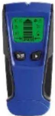
Blue handheld electronic device with green display and control buttons (no visible text or symbols)USER MANUAL 3
GEBRUIKERSHANDLEIDING 12
MODE D'EMPLOI 22
MANUAL DEL USUARIO 32
To all residents of the European Union
Important environmental information about this product

This symbol on the device or the package indicates that disposal of the device after its lifecycle could harm the environment. Do not dispose of the unit (or batteries) as unsorted municipal waste; it should be taken to a specialized company for recycling. This device should be returned to your distributor or to a local recycling service. Respect the local environmental rules.
If in doubt, contact your local waste disposal authorities.
Thank you for choosing Velleman! Please read the manual thoroughly before bringing this device into service. If the device was damaged in transit, do not install or use it and contact your dealer.
2. Safety Instructions
 | Keep this device away from children and unauthorized users. |
 | Keep this device away from rain, moisture, splashing and dripping liquids. |
 | Protect this device from shocks and abuse. Avoid brute force when operating the device. |
 | Protect the device against extreme heat and dust. |
 | There are no user-serviceable parts inside the device. Refer to an authorized dealer for service and/or spare parts. |
3. General Guidelines
Refer to the Velleman® Service and Quality Warranty on the last pages of this manual.
- Familiarise yourself with the functions of the device before actually using it.
• All modifications of the device are forbidden. - Only use the device for its intended purpose. Using the device in an unauthorised way will void the warranty.
4. Features
This device can detect stud, metal and unshielded AC live wire. Press the Mode Switch Button to the desired mode.
- STUD SCAN MODE: Three different stud modes for finding wood or metal studs. Choose the right scan modes can help the accuracy of the scanning. If you don't know the depth of the detection, it is recommended to use 1/2" scan mode first. When the 1/2" scan mode is not detected, use 1" or 1 1/2" scan mode instead.
- Stud 1/2 inch. Scan Mode: Detects wood or metal studs up to 1/2 in. (13 mm) deep.
- Stud 1 inch. Scan Mode: Detects wood or metal studs up to 1 in. (25 mm) deep.
- Stud 1 1/2 inch. Scan Mode: Detects wood or metal studs up to 1 12 in. (38 mm) deep.
• METAL SCAN MODE: Detects metal up to 2.36 in. (60 mm) deep.
- AC SCAN MODE: Detects live unshielded AC wires up to 2 inch. (51mm) deep
5. Overview
Refer to the illustrations on page 2 of this manual.
| 1 | The Center Marking Point |
| 2 | Stud Mode Indication |
| 3 | Metal Mode Indication |
| 4 | AC Mode Indication |
| 5 | AC Wire Warning |
| 6 | 1/2 in.Stud Scan mode |
| 7 | 1 in.Stud Scan mode |
| 8 | 1 12 in.Stud Scan mode |
| 9 | Power Button |
| 10 | Mode Switch Button |
| 11 | Scan Button |
| 12 | Battery case (Back) |
| 13 | Stud direction indication |
| 14 | Low Battery Indication |
6. Battery
- To replace the battery, make sure the device is switched off.
- Open the battery compartment at the back.
- Take out the old battery and replace with a new and identical 9 V (6F22) battery following the polarity markings inside the compartment.
- Close the battery compartment.
Low Battery Indicator: When the battery level is low, the screen will display a low battery icon, indicating that the battery needs to be replaced.

Warning: Do not puncture batteries or throw them in fire as they may explode. Do not attempt to recharge non-rechargeable batteries (alkaline). Dispose of batteries in accordance with local regulations. Keep batteries away from children.
7. Calibrating the tool
The device can be calibrated anywhere on the wall.
- Place the device on the surface of the wall, press the Power Button to turn on the device.
- Press the Scan button to start the calibration, the LCD will appear a signal strength from strong to weak. The calibration will be completed when bars decrease and a buzzer beeps one time. (Keep the tool flat against the wall and begin scanning.)
Note:
- It is important to wait for calibration to complete (2–3 seconds) every time before moving the device.
- Move the device slowly while keeping it flat against the wall. Do not shake or lift the device.
- For the best scanning results, it is important to hold the device correctly and move it correctly when scanning
8. Important operating tips
For optimum scanning results, it is important to properly hold the device and move slowly when scanning. The following tips will provide more accurate scanning results:
- Hold the handle with your thumb on one side and your fingers on the other side. Make sure your fingertips are on the handle and do not touch the surface or the scanning head being scanned.
- Hold the device steadily, parallel to the studs, and do not rotate the device.
- Keep the device flat against the wall, and slowly slide it across the scanned surface, do not rock, tilt, or press hard the device.
- Avoid placing your other hand, or any other part of your body, on the surface being scanned. This will interfere with the performance of the device.
- If you receive irregular scanning results, it may be a result of humidity, moisture within the wall cavity or drywall, or recently applied paint or wallpaper that hasn't fully dried. While the moisture may not always be visible, it will interfere with the device's sensors. Please allow a few days for the wall to dry out.
- Depending on how close the wires or pipes are to the wall surface, the device may detect them in the same way as studs. Caution should always be used when nailing, cutting, or drilling in walls, floors, and ceilings that may contain these items.
• To avoid accidents, remember that studs or joists are normally spaced 16 or 24 in. (41 or 61 cm) apart and are 11/2 in. (38
mm) in width.
Anything closer together or a different width may not be a stud, joist, or firebreak. Always turn off power when working near electrical wires.
SCANNING DIFFERENT SURFACES
This device is for use on dry interior walls only.
Freshly painted walls: May take one week or longer to dry after application.
Notes: Sensing depth and accuracy can vary due to moisture, content of materials, wall texture, and paint.
This device is not designed to scan materials such as: Ceramic floor tiles, carpet and underlayment, laths and plaster walls, insulation boards with foil covering, glass, or any other dense material.
WARNING: Do not rely exclusively on the device to locate the objects behind the scanned surface, use other sources of information for help whenever possible. These additional sources include construction plan drawings, such as visible entry points and wiring of walls in basement pipes, and standard 16 and 24 in. (41 and 61 cm) Stud spacing practices.
9. Scanning in stud mode
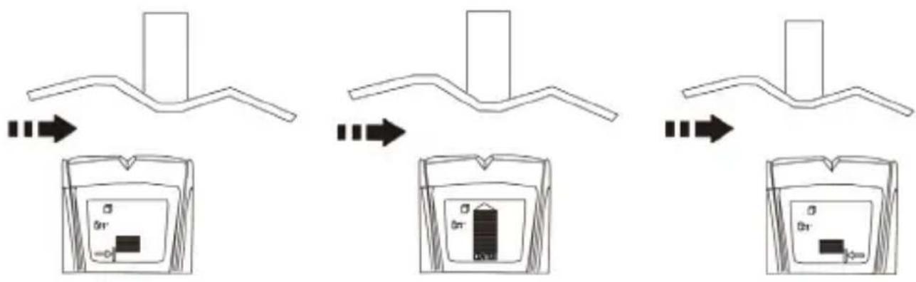
- Move the device slowly from left to right across the scanning surface. When the device approaches the stud, A bottom arrow indicator will light up. and EDGE indicator will light up when the device approaches near the edge, indicating location of the stud edge.
- Continue sliding the device. When the center of a stud is located, the signal full bar, the CENTER indication will all display and the buzzer will beep. In cases of thicker walls, when the center of the stud is located, not full bars will display on the screen. If you still cannot locate a stud, try Stud 1 inch Or Stud 1 1/2 inch scan mode.
Note: In cases of the screen "CAL" icon flashes and the buzzer alerts when moving the device, it may be incorrectly calibrated, please move the device to a different position to re-calibrate.
flowchart
graph TD
    A["Initial Component"] --> B["Device with 0n+"]
    B --> C["Device with 0n-"]
    C --> D["Final Device with 0n+"]
10. Scanning in metal mode
Metal Scan mode has interactive calibration to suit its sensitivity to the metal, which can be used to find the precise location of metal objects in walls, floors and ceilings. Maximum sensitivity is ideal for quickly finding the approximate location of metal. However sensitivity can be reduced by calibrating the device closer to metal. When the sensitivity decreases, the area where metal is indicated will be smaller. In both cases, the metal target is in the center of the area where the device indicates metal is present.
For maximum metal sensitivity, turn on the device in the air by pressing the Scan button, keep the device still before the calibration has completed. This will ensure that it calibrates away from any metal objects.
Note: Under metal detecting mode, please make sure that it is far away from other metals, wires and objects with strong magnetic field when power on and calibration.
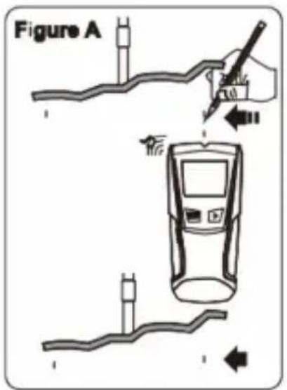
- (Figure A) While holding the Scan button, press the device flat against the wall and slowly slide the device across the surface. Mark the point where you get the highest metal indication (the most Middle bars on the screen). If it is a strong target, the top indicated arrow will show, and a steady beep will sound. Continue in the same direction until display bars reduce. Reverse direction and mark the spot where the display bars peak from the reversed direction.
The midpoint of the two marks is the location of the center of the metal object. If the device indicates metal over a large area, you can refine the scanning area to more accurately locate the metal target by following below steps 2 and 3.
DEM600
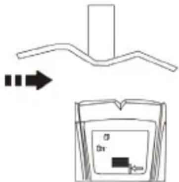
- (Figure B) To further pinpoint the location of the metal target, scan the area again. Release the Scan button and then turn the device back on, this time starting on the wall over one of the previous marks. This will reset the device to a lower sensitivity and narrow the scan area.
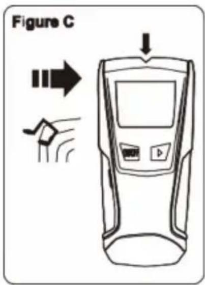
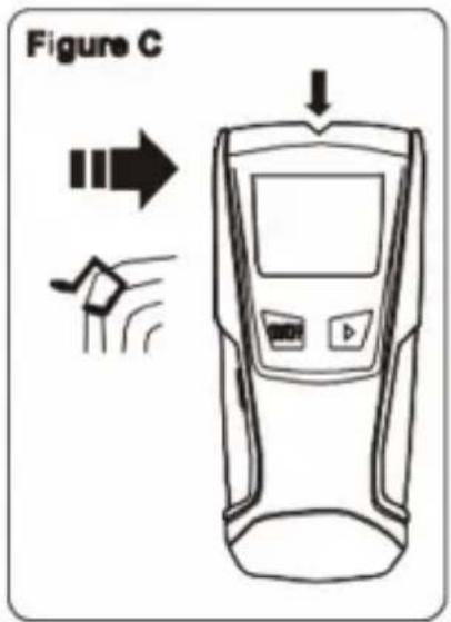
- (Figure C) To continue to reduce sensitivity and further refine the scanning area, repeat step 2. This process can be iterated several times to further refine the field. Scan in the opposite direction and mark the peak highest point to accurately locate the metal position.
Note: If any bars display on the screen, metal is present. Small targets or targets deep within the surface may only illuminate some of the bars and not the center line or audio tone. In this case, use the highest indication to determine the metal position.

11. Scanning in AC mode
AC Scan Mode has interactive calibration. The calibration and detecting process is the same as metal mode.
- (Figure A) Press Mode Switch Button to AC Scan mode. Press the device flat against the wall, then press scan button. Wait for the beep to confirm calibration has completed before moving the device. Once calibration has completed, move slowly the device across the scanning surface.
Mark the location where you get the highest AC indication (the most Middle bars on the screen). If it is a strong target, the top indicated arrow will show, and a steady beep will sound. Continue in same direction until display bars reduce. Reverse direction and mark the spot where the display bars peak from the reversed direction. The midpoint of the two marks is the location of the center of the live AC wiring.
DEM600
If the device indicates live electricity over a large area, you can reduce the sensitivity of the device to refine the scanning area and more accurately locate the live AC wiring by following steps 2 and 3.
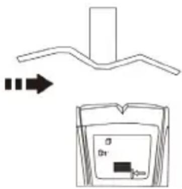
- (Figure B) To further pinpoint the location of the live AC wiring, scan the area again.
Release the Scan button and then turn the device back on, this time starting on the wall over one of the previous marks. This will reset the device to a lower sensitivity and narrow the scan area. - (Figure C) Scan in both directions as in Step 2. The area indicated should become smaller so you can more precisely identify the location of live AC wires. This procedure can be repeated multiple times to narrow the field even further. Scan in the opposite direction and mark the peak highest point to accurately locate the AC position.
Note: If any bars display on the screen, AC voltage is present. Small targets or targets deep within the surface may only illuminate some of the bars and not the center line or audio tone. In this case, use the highest indication to determine the AC position.
Note: AC Scan will only detect live (hot) unshielded AC wiring. Please refer to the WARNING statement in chapter 12, AC wire warning, for more important details and warnings about AC detection.
12. AC wire warning
AC warning detection feature works continuously in Stud 1/2 inch, Stud 1 inch, Stud 1 1/2 inch Scan modes, and Metal Scan Mode. When live AC voltage is detected, the AC detection warning indicator will appear in the display. If scanning begins over a live AC wire, the AC Wire Warning will show continuously. Use extreme caution under these circumstances or whenever live AC wiring is present.
WARNING Electrical field locators may not detect live AC wires if wires are more than 2 in. (51 mm) from the scanned surface, in concrete, encased in conduit, present behind a plywood shear wall or metallic wall covering, or if moisture is present in the environment or scanned surface.
DO NOT ASSUME THERE ARE NO LIVE ELECTRICAL WIRES IN THE WALL. DO NOT TAKE ACTIONS THAT COULD BE DANGEROUS! IF THERE IS AN ACTIVE ELECTRICAL WIRE IN THE WALL. ALWAYS TURN OFF THE ELECTRICAL POWER, GAS, AND WATER SUPPLIES BEFORE PENETRATING A SURFACE. FAILURE TO FOLLOW THE INSTRUCTIONS MAY RESULT IN ELECTRIC SHOCK, FIRE, AND/OR SERIOUS INJURY OR PROPERTY DAMAGE.
Always turn off power when working near electrical wires.
13. Cleaning and Maintenance
- Wipe the device regularly with a moist, lint-free cloth. Do not use alcohol or solvents. DO NOT submerge the device in any liquid.
• Store the meter in a dry place away from humidity and vibrations. - Remove the battery when the meter is to be stored for long periods of time.
14. Technical Specifications
| Number of scan modes | 3 |
| Detection mode | AC live wire up to 51 mm, Metal rebar up to 60 mm, Wood/metal stud up to 13 mm, Wood/metal stud up to 25 mm, Wood/metal stud up to 38 mm |
| Number of batteries | 1 |
| Battery voltage rating | 9 V |
| Battery composition | Alkaline |
| Battery IEC size | E (6LR61, 6LP3146, 6F22, 6KR61, 6HR61,1604A, 1604D, 1604LC, 7.2H5, 11604,11604M, PP3, 9-volt, 006P, MN1604) |
| Depth unit | 30 mm |
| Height unit | 154.7 mm |
| Width unit | 69.5 mm |
| Weight unit | 158 g |
| Material | ABS |
| Additional material | Polypropylene TPR |
Use this device with original accessories only. Velleman Group nv cannot be held responsible in the event of damage or injury resulting from (incorrect) use of this device. For more info concerning this product and the latest version of this manual, please visit our website www.velleman.eu. The information in this manual is subject to change without prior notice.
DEM600
© COPYRIGHT NOTICE
The copyright to this manual is owned by Velleman Group nv. All worldwide rights reserved. No part of this manual may be copied, reproduced, translated or reduced to any electronic medium or otherwise without the prior written consent of the copyright holder.
GEBRUIKERSHANDLEIDING
1. Inleiding
natural_image
Symbol of a trash bin with crossed lines indicating no waste or discharge (no text or labels)flowchart
graph TD
    A["Initial structure: branched alkane"] --> B["Device with internal components"]
    B --> C["Intermediate: Device with internal layer and internal charge"]
    C --> D["Final product: Device with internal charge and internal charge"]
10. Scannen in metaalmodus
chemical
Chemical reaction diagram showing a polymer chain transforming into a container with labeled components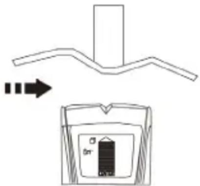
chemical
Chemical reaction diagram showing a polymer chain transforming into a device with a 0n+ charge and an arrow indicating transformation.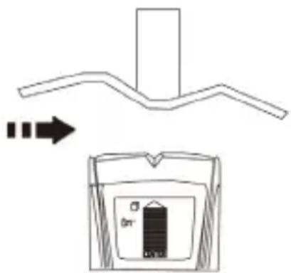

natural_image
Symbol of a trash bin with crossed lines indicating no waste or discharge (no text or labels)chemical
Chemical reaction diagram showing a curved alkane reacting with an arrow to form a device with 0n+ charge and -D charge.

flowchart
graph TD
    A["Initial structure with two branches, one branch ends"] --> B["Step 1: Initial structure changes"]
    B --> C["Step 2: Change in container with internal components"]
    C --> D["Step 3: Final step with internal components"]
Velleman® Service and Quality Warranty
Since its foundation in 1972, Velleman® acquired extensive experience in the electronics world and currently distributes its products in over 85 countries.
All our products fulfil strict quality requirements and legal stipulations in the EU. In order to ensure the quality, our products regularly go through an extra quality check, both by an internal quality department and by specialized external organisations. If, all precautionary measures notwithstanding, problems should occur, please make appeal to our warranty (see guarantee conditions).
General Warranty Conditions Concerning Consumer Products (for EU):
- All consumer products are subject to a 24-month warranty on production flaws and defective material as from the original date of purchase.
- Velleman® can decide to replace an article with an equivalent article, or to refund the retail value totally or partially when the complaint is valid and a free repair or replacement of the article is impossible, or if the expenses are out of proportion.
You will be delivered a replacing article or a refund at the value of 100% of the purchase price in case of a flaw occurred in the first year after the date of purchase and delivery, or a replacing article at 50% of the purchase price or a refund at the value of 50% of the retail value in case of a flaw occurred in the second year after the date of purchase and delivery.
• Not covered by warranty:
- all direct or indirect damage caused after delivery to the article (e.g. by oxidation, shocks, falls, dust, dirt, humidity...), and by the article, as well as its contents (e.g. data loss), compensation for loss of profits;
- consumable goods, parts or accessories that are subject to an aging process during normal use, such as batteries (rechargeable, non-rechargeable, built-in or replaceable), lamps, rubber parts, drive belts... (unlimited list);
- flaws resulting from fire, water damage, lightning, accident, natural disaster, etc....;
- flaws caused deliberately, negligently or resulting from improper handling, negligent maintenance, abusive use or use contrary to the manufacturer's instructions;
- damage caused by a commercial, professional or collective use of the article (the warranty validity will be reduced to six (6) months when the article is used professionally);
- damage resulting from an inappropriate packing and shipping of the article;
- all damage caused by modification, repair or alteration performed by a third party without written permission by Velleman®.
- Articles to be repaired must be delivered to your Velleman® dealer, solidly packed (preferably in the original packaging), and be completed with the original receipt of purchase and a clear flaw description.
- Hint: In order to save on cost and time, please reread the manual and check if the flaw is caused by obvious causes prior to presenting the article for repair. Note that returning a non-defective article can also involve handling costs.
- Repairs occurring after warranty expiration are subject to shipping costs.
- The above conditions are without prejudice to all commercial warranties.
The above enumeration is subject to modification according to the article (see article's manual).
NL


- To all residents of the European Union
- Important environmental information about this product
- If in doubt, contact your local waste disposal authorities.
- Safety Instructions
- General Guidelines
- Features
- Overview
- Battery
- Calibrating the tool
- Note:
- Important operating tips
- SCANNING DIFFERENT SURFACES
- Scanning in stud mode
- Scanning in metal mode
- DEM600
- Scanning in AC mode
- AC wire warning
- Cleaning and Maintenance
- Technical Specifications
- © COPYRIGHT NOTICE
- GEBRUIKERSHANDLEIDING
- Inleiding
- Scannen in metaalmodus
- Velleman® Service and Quality Warranty
- General Warranty Conditions Concerning Consumer Products (for EU):
- • Not covered by warranty:
- The above enumeration is subject to modification according to the article (see article's manual).
- NL
Brand : VELLEMAN
Model : DEM600
Category : Detector