C.A 6609 - Measuring equipment CHAUVIN ARNOUX - Free user manual and instructions
Find the device manual for free C.A 6609 CHAUVIN ARNOUX in PDF.


User questions about C.A 6609 CHAUVIN ARNOUX
0 question about this device. Answer the ones you know or ask your own.
Ask a new question about this device
Download the instructions for your Measuring equipment in PDF format for free! Find your manual C.A 6609 - CHAUVIN ARNOUX and take your electronic device back in hand. On this page are published all the documents necessary for the use of your device. C.A 6609 by CHAUVIN ARNOUX.
USER MANUAL C.A 6609 CHAUVIN ARNOUX
natural_image
Diagram of a mechanical device with a labeled component 'R' and internal components, showing rotational flow (no text or symbols beyond label)Dimensions (H x L x P) : 130 x 69 x 32mm
Poids : 170g
9.3 CARACTÉRISTIQUES ENVIRONNEMENTALES
9.4 CONFORMITÉ NORMATIVE
IEC 61010-1, DIN VDE 0411;
You have just purchased a CA 6609 motor and phase rotation indicator and we thank you for your confidence.
For best results from your device:
• read this user manual attentively,
• observe the precautions for its use.
Meaning of the symbols used on the instrument
 | Warning, possible hazard. Please refer to the user's manual. |
 | Correct orientation of the motor when positioning the instrument. |
 | Battery |
 | Instrument protected by double insulation. |
 | The CE marking guarantees compliance with European directives and with the regulations governing EMC. |
 | Selective sorting of wastes for the recycling of electrical and electronic equipment within the European Union. In conformity with directive WEEE 2002/96/E C: this equipment must not be treated as household waste. |
 | Earth. |
English
Definitions of the measurement categories:
β CAT I: Circuits not directly connected to the network and specially protected.
Example: protected electronic circuits.
β CAT II: Circuits directly connected to the low-voltage installation.
Example: power supply to household electrical appliances and portable tools.
β CAT III: Power supply circuits in the installation of the building.
Example: distribution panel, circuit-breakers, fixed industrial machines or devices.
β CAT IV: Circuits supplying the low-voltage installation of the building.
Example: power lines, meters, and protection devices.
1. PRECAUTIONS AND SAFETY IN USE
This instrument complies with safety standard IEC 61010-1.
For your own safety, and to prevent any damage to your instrument, you must follow the instructions given in this manual.
This instrument is not a safety voltage tester. So, don't use L1, L2, L3 lights as safety information for phases voltage presence or absence. Use always a safety voltage tester to do this verification.
English
This instrument can be used on category III electrical circuits not exceeding 600V with respect to earth. It must be used indoors, in an environment not exceeding pollution level 2, at an altitude of not more than 2000m. The instrument can therefore be used in complete safety on 400V three-phase networks in an industrial environment.
β For safety reasons, you must use only measurement leads having a voltage rating and category at least equal to those of the instrument and compliant with standard IEC 61010-031.
β Do not use if the cover of the battery compartment is missing or if the housing is damaged or not correctly closed.
β Do not place your fingers near unused terminals.
β If the instrument is used other than as specified in this manual, the protection provided by the instrument may be impaired.
β Do not use this instrument if it seems to be damaged.
β Check the integrity of the insulation of the leads and of the housing. Replace damaged leads.
β Be prudent when working in the presence of voltages exceeding 70Vdc or 33Vrms and 46.7Vpp; such voltages can cause a risk of electrocution. The use of individual protections is recommended in some cases.
β Always keep your hands behind the physical guards of the probe tips or alligator clips.
β Always disconnect all leads from the measurement and from the instrument before opening the housing.
β Always use the specified type of battery.
2. UNPACKING - PACKAGING
All instruments undergo mechanical and electronic testing before being dispatched. Every precaution is taken to ensure that the instrument reaches you in good condition. If there is any damage, inform the carrier immediately.
3. INTRODUCTION
The CA 6609 is designed to facilitate installing three-phase electrical power supply networks and combines the following functions in a single instrument:
β Determination of the direction of phase rotation;
β Presence or absence of phase ( if voltage between phases and neutral is > 100V);
β Determination of the direction of rotation of a motor with or without connection;
β Determination of the activation of a solenoid valve without connection.
4. DESCRIPTION OF THE INSTRUMENT
text_image
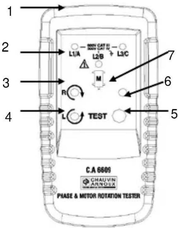
1 2 3 4 TEST L1/A L2/B L3/C M R C.A 6509 CHAUVIN ARNOUX PHASE & MOTOR ROTATION TESTER 7 6 51 Test lead input terminals
2 Indicators L1, L2, and L3
3 Green Clockwise rotation led
4 Red Anticlockwise rotation led
5 On/Off button
6 Green On led
7 Symbol for CA 6609 correct orientation on the motor (§ 6)
5. USING THE INSTRUMENT
5.1 DIRECTION OF PHASE ROTATION
On a three-phase electrical network:
- Connect the 3 leads to the instrument, matching the markings.
- Connect the 3 alligator clips to the 3 phases of the network to be tested.
- Press the ON button. The green indicator indicates that the instrument is in operation.
- The clockwise (or anticlockwise) rotation indicator indicates the direction of phase rotation.
English
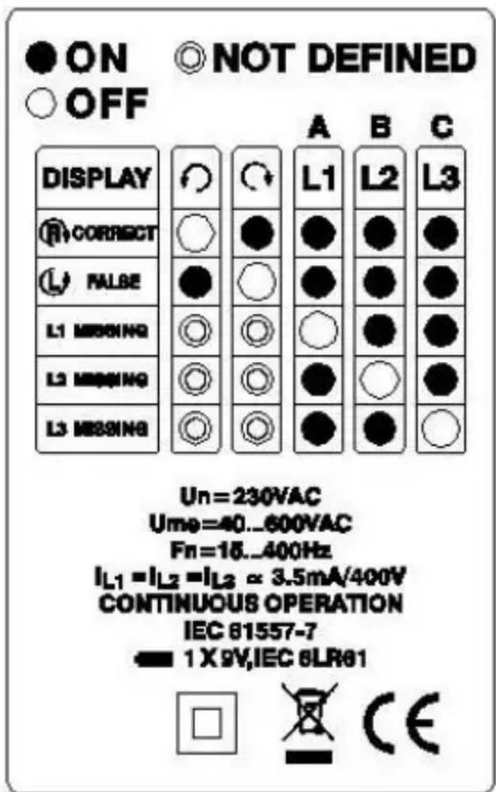
Warning: the wrong direction of rotation may be displayed if a lead is connected by mistake to the neutral of the network.
The table below (reproduced on the back of the instrument) summarizes the various display possibilities.
text_image
ON OFF NOT DEFINED DISPLAY CORRECT FALSE L1 MISSING L2 MISSING L3 MISSING A B C L1 L2 L3 Un=230VAC Ume=40...600VAC Fn=18...400Hz IL1=IL2=IL3 ≈ 3.5mA/400V CONTINUOUS OPERATION IEC 81557-7 1 X 9V,IEC 8LR81 CECaution: Phasis lights L1, L2, L3 can be off if voltage is too low (see § 3 introduction).
English
6. INDICATION OF THE DIRECTION OF THE ROTATING FIELD OR DIRECTION OF ROTATION WITHOUT CONNECTION
- There must be no lead connected to the instrument;
- Position the instrument on the motor, within 2.5 cm, parallel to the shaft in the direction indicated by the symbol on the front panel.
- Press the ON button. The green indicator indicates that the instrument is in operation.
- The clockwise or anticlockwise rotation indicator lights to indicate the direction of the rotating field.
Note: the instrument does not work on motors controlled by frequency converters.
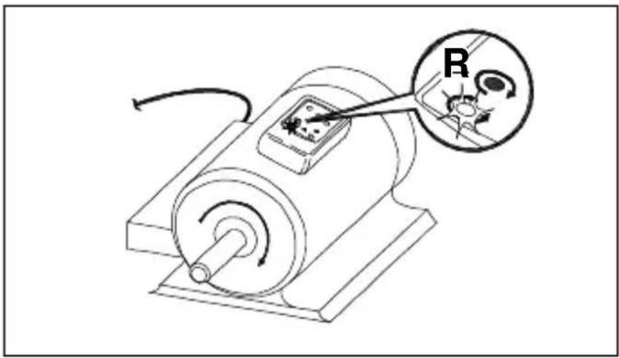
text_image
Diagram of an electrical circuit with a motor, switch, and labeled component 'R' (electrolytic resistor)English
The table below summarizes the conditions necessary to obtaining a reliable test result.
| Number of pairs of poles | Number of rotations of the rotating field (per minute) as a function of frequency (Hz) | Angle between poles | Minimum dia. of the motor casing | ||
| 16 2/3 | 50 | 60 | 0 | cm | |
| 1 | 1000 | 3000 | 3600 | 60 | 5.3 |
| 2 | 500 | 1500 | 1800 | 30 | 10.7 |
| 3 | 333 | 1000 | 1200 | 20 | 16.0 |
| 4 | 250 | 750 | 900 | 15 | 21.4 |
| 5 | 200 | 600 | 720 | 12 | 26.7 |
| 6 | 167 | 500 | 600 | 10 | 32.1 |
| 8 | 125 | 375 | 450 | 7.5 | 42.8 |
| 10 | 100 | 300 | 360 | 6 | 53.5 |
| 12 | 83 | 250 | 300 | 5 | 64.2 |
| 16 | 62 | 188 | 225 | 3.75 | 85.6 |
7. DETERMINATION OF THE DIRECTION OF CONNECTION OF THE PHASE WIRES TO A MOTOR
- Connect the 3 leads to the instrument, matching the markings;
- Connect the 3 alligator clips to the 3 phase pins of the connector of the motor being tested;
- Press the ON button. The green indicator indicates that the instrument is in operation;
- Turn the motor shaft a half-turn to the right;
- The clockwise or anticlockwise rotation indicator lights, indicating whether or not the order of connection of the phase wires is correct.
8. INDICATION WITHOUT CONNECTION OF THE ACTIVATION OF A SOLENOID VALVE
- There must be no lead connected to the instrument;
- Place the instrument as close as possible to the solenoid valve;
- Press the ON button. The green indicator indicates that the instrument is in operation;
- The clockwise or anticlockwise rotation indicator lights, indicating the presence of the field generated during the activation.
9. TECHNICAL SPECIFICATIONS
9.1 ELECTRICAL CHARACTERISTICS
Maximum rated voltage: 600V, CAT III
Operating voltage, in phases rotation use:
With connections: 40 to 600VAC between phases (see § 5.1 and 7)
Without connection: 120 to 400V AC between phases (see § 6)
Frequency of operation: 15 to 400Hz
Test current (per phase): less than 3.5mA
Power supply: 9V battery (6LR61, 6LF222, 1604A, NEDA 1604)
Consumption less than 20mA.
L1, L2, L3 lights are on, since 100V voltage between phases and neutral.
24
English
9.2 MECHANICAL CHARACTERISTICS
Dimensions (H x L x D): 130 x 69 x 32mm
Weight: 170g
9.3 ENVIRONMENTAL CHARACTERISTICS
Operating temperature: 0 to 40°C
Storage: -20^ < T < +50^, RH < 80%
Operating relative humidity: 15 to 80%
Operating altitude: less than 2000 m
Operating pollution level: less than 2
9.4 COMPLIANCE WITH STANDARDS
IEC 61010-1, DIN VDE 0411;
Tightness: IP 40 (as per IEC 60529)
10. MAINTENANCE
10.1 CLEANING
Disconnect from all sources of electricity before cleaning, servicing, dismantling.
Clean only with a soft cloth moistened with soapy water, then plain water.
Dry completely and perfectly before using again.
English
10.2 REPLACING THE BATTERY
To replace the battery, proceed as follows:
- Disconnect the leads from the measurement source and from the instrument;
- Loosen the screw at the bottom of the back of the instrument;
- Remove the cover from the battery compartment;
- Replace the battery and attach the cover using the screw.
Reminder: for your safety, never use the instrument if the battery compartment cover is missing, damaged, or incorrectly installed.
10.3 STORAGE
If the instrument will be out of use for a long period, it is best to store the instrument and the battery separately.
10.4 METROLOGICAL CHECK
Like all measuring or testing devices, the instrument must be checked regularly.
This instrument should be checked at least once a year. For checking and calibration, contact one of our accredited metrology laboratories (information and contact details available on request), at our Chauvin Arnoux subsidiary or the branch in your country.
11. WARRANTY
This instrument is warranted against defects of materials and workmanship, in conformity with the general conditions of sale.
During the warranty period (1 year), the instrument must be repaired only by the manufacturer, who reserves the right to repair the instrument or to replace it in whole or in part.
The warranty does not cover the following cases:
- improper use of the instrument or use with incompatible equipment;
- changes made to the instrument without the explicit permission of the manufacturer's technical department;
- work done on the instrument by persons not authorized by the manufacturer;
- adaptation to a specific application not anticipated in the definition of the instrument or the user's manual;
- shocks, falls, or immersion.
12. REPAIR
For all repairs before or after expiry of warranty, please return the device to your distributor.
13. PER ORDER
Motor and phase rotation indicator CA6609....P01191305
Delivered with the following items:
- 3 test leads - black, red, blue
- 3 alligator clips - black
- Carrying bag,
- User's manual.
text_image
Diagram of an electric motor with a labeled component 'R' and its internal circuit, showing wiring connections.Deutsch
10.2 BATTERIEWECHSEL
text_image
Diagram of an electrical device with labeled component 'R' and internal components, showing a rotary switch and motor control.Dimensioni (H x L x P): 130 x 69 x 32mm
Peso: 170g
9.3 CARATTERISTICHE AMBIENTALI
9.4 CONFORMITÀ NORMATIVA
IEC 61010-1, DIN VDE 0411;
text_image
Technical diagram showing a mechanical device with a labeled component 'R' and directional arrows indicating motion or operation.Unit 1 Nelson Ct – Flagship Sq – Shaw Cross Business Pk
Dewsbury, West Yorkshire – WF12 7TH
Tel: 1924 460 494 - Fax: 01924 455 328
MIDDLE EAST - Chauvin Arnoux Middle East
P.O. BOX 60-154 - 1241 2020 JAL EL DIB (Beirut)
LEBANON
Tel: (01) 89 04 25 - Fax: (01) 89 04 24
CHINA - Shanghai Pu-Jiang - Enerdis Instruments Co. Ltd
3 F, 3 rd Building - N° 381 Xiang De Road - 200081 SHANGHAI
Tel: +86 21 65 21 51 96 - Fax: +86 21 65 21 61 07
USA - Chauvin Arnoux Inc - d.b.a AEMC Instruments
200 Foxborough Blvd. - Foxborough - MA 02035
Tel: (508) 698-2115 - Fax: (508) 698-2118
http://www.chauvin-arnoux.com