C.A 6462 - Measuring equipment CHAUVIN ARNOUX - Free user manual and instructions
Find the device manual for free C.A 6462 CHAUVIN ARNOUX in PDF.


User questions about C.A 6462 CHAUVIN ARNOUX
0 question about this device. Answer the ones you know or ask your own.
Ask a new question about this device
Download the instructions for your Measuring equipment in PDF format for free! Find your manual C.A 6462 - CHAUVIN ARNOUX and take your electronic device back in hand. On this page are published all the documents necessary for the use of your device. C.A 6462 by CHAUVIN ARNOUX.
USER MANUAL C.A 6462 CHAUVIN ARNOUX
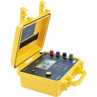
Earth & Resistivity Ohmmeter
C.A 6462:Batterie rechargeable NiMH
Recharge ext. : 120-230 V / 50-60 Hz, 20 VA
Thank you for purchasing this C.A. 6460 or C.A. 6462 ohmmeter for earth and resistivity measurement.
To obtain the best possible service from your instrument:
read this operation manual carefully,
comply with the precautions for use.

WARNING, DANGER! The operator should refer to this user's manual whenever this danger symbol appears.

Equipment protected by double insulation.

The CE marking indicates conformity with European directives, in particular LVD and EMC.

The rubbish bin with a line through it indicates that, in the European Union, the product must undergo selective disposal in compliance with Directive WEEE 2002/96/EC. This equipment must not be treated as household waste.
PRECAUTIONS FOR USE
Comply with the conditions for use: temperature, humidity, pollution level.
This instrument can be used on category III installations: Category III meets severe reliability and availability requirements, corresponding to permanent use on fixed industrial installations (see IEC 664-1).
Only use the instruments on installations that are not live.
- To prevent the using mistakenly touching the terminal linked to the mains electricity supply, you are advised to check the voltage on the sockets before connecting the instrument.
- Do not perform any measurements when the leads are connected and the instrument's buzzer is sounding.
- Check that all the terminals are disconnected before replacing the fuse or the batteries (C.A 6460).
Recharge the battery in accordance with the mains voltage (C.A 6462). - Make sure that you replace the battery pack (C.A 6462) with an appropriate battery pack.
Respect the value and type of the fuse to avoid damaging the instrument and cancelling the warranty.
1. PRESENTATION
The C.A 6460 and C.A 6462 are ohmmeters equipped with digital displays for earth and resistivity measurements in the field.
They are particularly well-adapted to use in difficult conditions, in the presence of interference voltages, high earth currents or highly resistive auxiliary connections, in accordance with standards NF EN 61010-2-032, NF EN 61557 parts 1 and 5, NF EN 61326-1.
For easier handling, the instrument is equipped with:
a single pushbutton for activation of measurement,
an automatic switching system for the measurement calibre,
a large-size backlit liquid crystal display,
- three LEDs indicating the presence of faults which may invalidate the measurement result,
■ four coloured screw terminals to simplify connection of the leads,
a captive connection strap.
CONTENTS
- PRESENTATION 17
2.DESCRIPTION 18 - USE 19
3.1. Implementation 19
3.2.Earth resistance measurement 19
3.3. Measurement of earth resistivity 20
3.4.Measurement of coupling 21
3.5.Fault signalling 21
- FUNCTIONAL CHARACTERISTICS 22
4.1. Reference conditions 22
4.2.Metrological properties 22
4.3.Power supply 23
4.4.Environmental parameters 23
4.5.Construction specifications 24
4.6.Compliance with international 24
5.MAINTENANCE 26
5.1. Servicing 26
5.2.Cleaning 28
5.3.Storage 28
5.4.Metrological verification 28
5.5. Repair 28
6.WARRANTY 28
7.DELIVERY CONDITION 29
2.DESCRIPTION
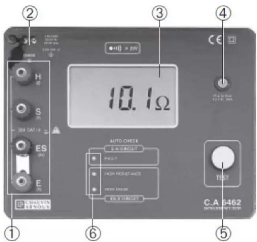
① Four measurement terminals marked E (X), ES (Xv), S (Y) and H (Z)
② Mains socket equipped with a cover to protect it from dust (only on C.A 6462). Battery charge LED (only on C.A 6462); when it is lit continuously, it indicates that the battery is being charged. It changes colour when charging has finished.
③ LCD display with backlighting which lights up whenever the ⑤ pushbutton is pressed.
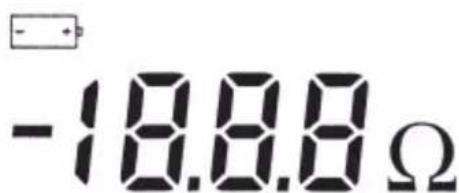
The liquid crystal display includes the digital display of the measured values, the related units and symbols. The "minus" sign indicates reversal of the measurement conditions.
The "1" sign alone on the left of the screen indicates that the measured resistance is greater than 1999 .
indicates that the power supply is too low to make a correct measurement.
④ Fuse holder.
⑤ Fleeting control measurement pushbutton used for starting up the equipment and tripping the measurements.
As soon as the pushbutton is released, the equipment is turned off.
⑥ Three indicator lights that flash when the measurement is not valid (see 3.5 fault signalling).
-
«FAULT»: if the current circuit resistance is too high if the current circuit resistance is too high if the fuse is defective.
-
«HIGH RESISTANCE»: means that the measurement is liable to be over-affected by the resistance in the S.ES voltage circuit.
- «HIGH NOISE»: if there is too much interference in the S.ES voltage circuit, it means that the electronics saturated and the measurement is no longer valid.
The equipment is also provided with a cover and a transport handle.
Buzzer
The equipment features a buzzer which buzzes when the terminals of the equipment are connected to a voltage source.
The sound volume is proportional to the voltage up to approximately 30V then becomes stable.
3. USE
3.1. IMPLEMENTATION
- Connect the cords to the equipment using the forked terminals and in compliance with the terminal colours.
Pay out the cords and set the stakes at the ends.
Connect the cords to the stakes using the alligator clips.
Return to the equipment, press the pushbutton and read the measurement results
3.2.EARTH RESISTANCE MEASUREMENT
To measure the earth resistance, it is advisable to use the "62% method (method using two stakes). This measurement requires the use of the earth Kit components (see paragraph 7 Delivery condition).
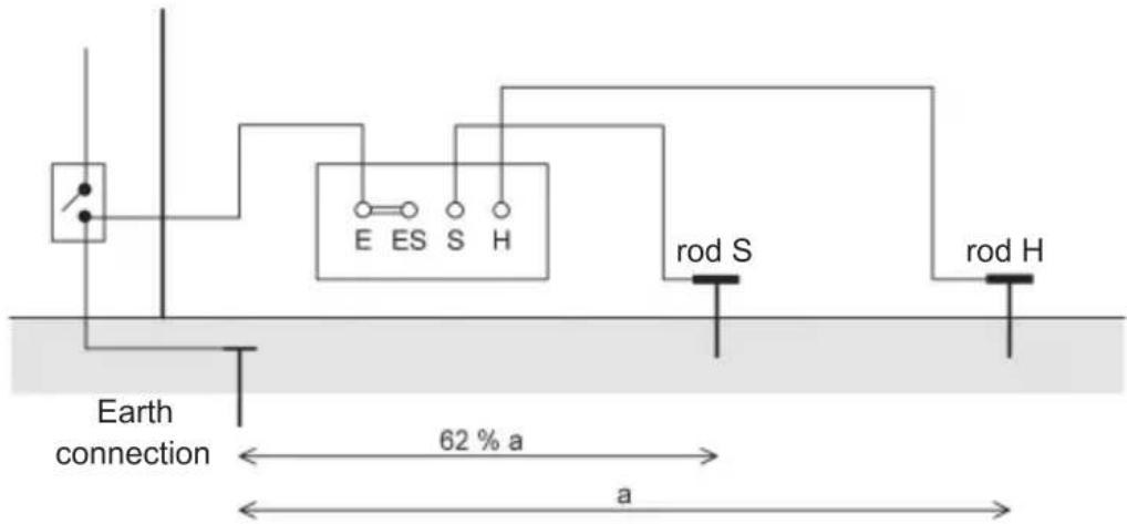

Turn off the installation power supply and disconnect it from the earth opening the ground terminal bar.
- Short-circuit the terminals E and ES using the corresponding terminal bar and connect them to the earth point to be measured.
- Push rod H as deep as possible into the ground at a distance "a" from the earth to be measured.
Note: the deeper the earth the greater this distance should be (larger area of influence). If possible, it is advisable to have a distance “a” >25m
- Insert rod S into the ground on a line between the earth connection E and rod H, at a distance of 62% of "a".
- Connect the rods to their respective terminals on the instrument, using the leads.
- Press the ⑤ button until the measurement is displayed.
Make sure that none of the three indicators is flashing, otherwise check the setup (see § 3.5 Fault signalling) and start measuring again.
Checking the measurement.
- Note the measurement value previously obtained.
- Redo a measurement a few moments later.
- Move rod S toward H over a distance of 10% of "a".
Measure and note the result.
- From the initial position, move the rod S toward E over a distance of 10% of "a". Measure and note the result.
If the three measurements are of the same magnitude, the measurement is correct. Otherwise, increase "a" and start the entire operation again.
Note: To counter the resistance of the lead E (approxima 22.5m /m for the lead supplied in the kit), it is better to disconnect the terminal bar and connect the ES terminal to the earth to be measured.
Remember to reconnect the earth terminal strip once you have finished measuring!
3.3. MEASUREMENT OF EARTH RESISTIVITY
This measurement is used for choosing, when possible, the best location and shape of the earth point before it is built. This measurement is made using the WENNER method described below. It requires the use of the components of the resistivity kit (see para. 7 Delivery condition).
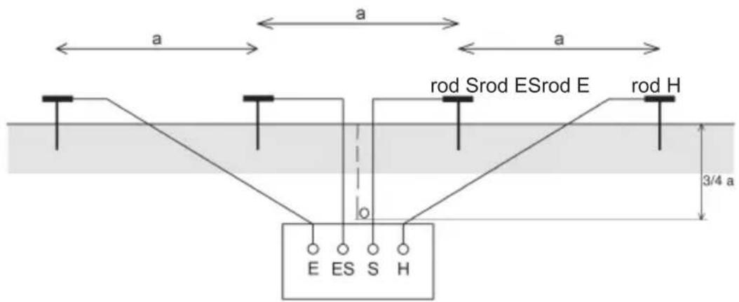
- Check that the terminal bar is disconnected between the terminals E and ES.
- Set out the four rods in a straight line at a constant interval "a".
- Connect the rods to their respective terminals on the instrument, using the leads.
- Press the ⑤ button until the measurement is displayed.
Make sure that none of the three indicators is flashing, otherwise check the setup (see § 3.5 Fault signalling) and start measuring again.
- Make a note of the measured resistance R.
- The ground resistivity at point O is obtained by calculation: = 2 × R× a (with in R in and a in metres)
3.4. MEASUREMENT OF COUPLING
This measurement can be made to determine the coupling resistance between two earth points. For instance, between the neutral earth point and the ground earth point (EDF distribution).
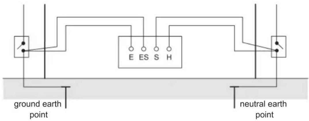

Cut off the installation power supply and disconnect .
- Open the terminal bar between the E and ES terminals.
- Using separate leads, connect the E and ES terminals to the ground earth point and the H and S terminals to the neutral earth point.
- Press the ⑤ button until the measurement is displayed. Make sure that none of the three indicators is flashing, otherwise check the setup (see 3.5 Fault signalling) and start measuring again.
- Note the Rmn value displayed.
- By also measuring Rm (ground earth resistance) and Rn (neutral earth resistance) using the 62% method described in 3.2 , the coupling coefficient can be calculated.
$$ k = \frac {R c}{R m} \text {h e n c e} R c = \frac {R m + R n - R m n}{2} $$
This coupling coefficient k must be < 0.15 (EDF recommendation).

Remember to reconnect the earth terminal strip once you have finished measuring!
3.5. FAULT SIGNALING
If the FAULT indicator light flashes:
- either the fuse is defective
- or the circuit is cut off.
- or the rod resistance is too high or the spurious voltage is excessive.
To check the fuse continuity, short circuit the H and E terminals and make a measurement. If the indicator light continues to flash, replace the fuse from the front panel (see para. 5.1.3. Maintenance) If the indicator light no longer flashes, the fuse is serviceable. You then need to check the connections.
If the HIGH RESISTANCE indicator light flashes: the resistance in the voltage circuit (between the S and ES terminals) is too high, or the voltage circuit is cut off. You then need to check the connections.
If the HIGH NOISE indicator light flashes: the spurious voltage is too high in the voltage circuit In this case, move the rods because they are in an area where there is too much interference.
If there is interferences and the measurement fluctuates (and none of the indicator lights is flashing). Measure the minimum and maximum then calculate the average to obtain the result.
To be more sure, make two consecutive measurements at intervals of a few seconds.
4. FUNCTIONAL CHARACTERISTICS
4.1.REFERENCE CONDITIONS
| Influence quantities Reference values | |
| Temperature 23°C ± 3 K | |
| Relative humidity 45 to 55 % HR | |
| Supply voltage 9,5 V ± 0,2 V | |
| Auxiliary resistances RH, RS, RES and RE zero | |
| Spurious voltages (AC and DC) zero | |
| Serial inductances zero | |
| Electrical Jeld < 1 V/m | |
| Magnetic Jeld < 40 A/m | |
4.2. METROLOGICAL PROPERTIES
4.2.1. Voltage detection
Measurement range: 20 to 250 VAC between the H and E terminals or between the S and E terminals.
Frequency: DC at 450 Hz.
4.2.2. Resistance
Measurement range: 0 to 2000 Ω
| Rating (Ω) | 0.00 - 19.99 | 20.0 - 199.9 | 200 - 1999 |
| Resolution (Ω) | 0,01 | 0,1 | 1 |
| Intrinsic error | ± 2 % ± 1 pt | ± 2 % ± 1 pt | 2 % typical 5% max ± 3 pt |
| Measuring current | 10 mA | 1 mA | 0,1 mA |
| No load voltage | ≤ 42 V peak | ||
Response time: 4 to 8 seconds
When the unit is locked on the second rating, the characteristics are as follows:
| Rating (Ω) 0.0 - 199.9 | |
| Resolution 0,1 Ω | |
| Intrinsic error | ± 2 % ± 1 pt |
| Measuring current | 1 mA |
| No load voltage | ≤ 42 V peak |
4.3. POWER SUPPLY
The equipment power supply is obtained from:
C.A 6460 : 8 1.5 V LR 14 batteries or rechargeable cells of the same size, NiMH.
C.A 6462 : NiMH rechargeable cell
External recharge: 120-230 V / 50-60 Hz, 20 VA
Charge time 6 h for charging to 80% of the battery capacity
(cf § 5.1.2)
| Equipment | C.A 6460 (8 LR 14 cells) | C.A 6460 (8 x 1.2 V, 2 Ah cells) | C.A 6462 (Battery pack) |
| Battery charge life average in continuous operation* | 4500 measurements 15 s or 18h45 | 1180 measurements 15 s or 4h55 | 2000 measurements 15 s or 9h35 |
- at the rating consuming most power.
The load limit of the power supply is indicated by the display
The capacity after this display is approximately 50 measurements of which only 20 are with rechargeable cells.
4.4. ENVIRONMENTAL PARAMETERS
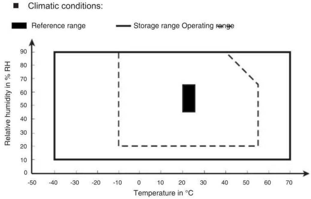
4.4.1.Climatic
Nominal range of use:
from -10^ to +55^
- from +20^ to +90% HR without condensation
Storage (without battery or rechargeable cell but with battery depending on model):
from -40^ to +70^
- from +10^ to +90% HR without condensation
4.5. CONSTRUCTION SPECIFICATIONS
Overall dimensions of the unit (L× W× H)
273× 247× 127mm
273× 280× 127mm with handle extended
Weight: 2.850 kg (C.A 6460)
3.350 kg (C.A 6462)
4.6. COMPLIANCE WITH INTERNATIONAL
Electrical safety as per: EN 61010-2-032, EN 61557
Dual insulation
Pollution level: 2
Installation category: III
Maximum operating voltage: 30V eff.
4.6.1. Electromagnetic compatibility:
Emissions and immunity in an industrial setting compliant with IEC 61326-1. Special precautions must be taken in a difficult EMC environment.
4.6.2. Mechanical protection
The C.A 6460 and 6462 have successfully undergone all the required mechanical tests (vibration/ rigidity / resistance to impact / free fall) and therefore meet all the requirements of the standards NF EN 61557 and NF EN 61010-2-032.
| Influence quantities | Operating range limits | Typical measurement variations | Maximum measurement variations |
| Temperature | -10 to +55°C | (0.% ±1 pt)/10°C | (1%±1 pt)/10°C |
| Relative humidity | 20 to 90% RH | 1% ±3 pt | 2% ±5 pt |
| Supply voltage | 7.5 to 13 V | 0.5% ±1 pt/V | 1% ±1 pt/V |
| Rvoltage (Rs + R + Res) | 50 kΩ | -0.6%/10 kΩ ±2 pt | -1%/10 kΩ ±4 pt |
| Rcurrent (RH + R + Re) | Calibre 1...30 kΩ (1) 2...30 kΩ 3...50 kΩ | 0,5%/10 kΩ ±1 pt | 1%/10 kΩ ±2 pt |
| Resistance into the 4 rods (RH = RS = RES = RE) | Calibre 1...15 kΩ (1) 2...15 kΩ 3...25 kΩ | (0.% ±0,3 Ω)/10 kΩ 0.%/10 kΩ 0.5%/10 kΩ | (1% ±0.6 Ω)/10 kΩ 1%/10 kΩ 1%/10 kΩ |
| DC voltage in series with R | 0 to 20 V (2) | - | Negligible |
| Spurious voltages AC in series with H | 0 to3 Vrms or 0 to 32.5 Vpeak at 16,67, 50, 60 or 400 Hz | 1% ±1 pt | 2% ±2 pt |
| AC spurious voltages in series with S | 0 to 9 Vrms or 0 to 13 Vpeak at 16,67, 50, 60 or 400 Hz | 0.2% ±1 pt | 0.5% ±2 pt |
| Inductance in series with H and S | 0 to 13 mH | - | Negligible |
(1) Beyond 3k the unit switches to calibre 2
(2) Risk of flashing HIGH RESISTANCE indicator light flashing beyond 4.5V.
4.6.4. Typical measurements
The following measurements are representative on-site.
Common measurement conditions:
- Ambient temperature
- 10.5 V power supply voltage
Measurement of three wire ground resistance:
- with 5k in each of the rods H and S,
- with 5 VRMS sinusoidal spurious voltage at 50 Hz in H and in S .
The error with respect to the real R values is less than 4% ± 5 pt.
(For resistance included between 0 and 20 the measurement can be displayed for calibre 2).
Four wire resistivity measurement:
-
with 5k in each of the four rods,
-
with 5 Vrms sinusoidal spurious voltage at 50 Hz in H and in S .
The error with respect to the real R values is less than 4% ± 5 pt.
(For resistance included between 0 and 20 the measurement will be displayed for calibre 2).
Note: The same measurements with rod resistances of 1k instead of 5k would give an error of less than 1% ± 2 pt.
4.6.5. Limits
According to NF EN 61557 part 5, free of damage when connected to 120% of the network voltage to which it is assigned. The user must not be exposed to voltage exceeding the contact voltage and the protection devices must not activate.
C.A 6460 and C.A 6462 are designed to operate with the network de-energised but if wrong manoeuvres are carried out, the equipment is designed to withstand and overload applied permanently between any two terminals for: 250 VAC or 100 VDC, with the possible blowing of the fuse.
5. MAINTENANCE
For maintenance, use only specified spare parts. The manufacturer will not be held responsible for any accident occurring following a repair done other than by its After Sales Service or approved repairers.
5.1. SERVICING
When the symbol is displayed, replace all the batteries of the C.A 6460
or recharge the battery of the CA 6462. Check that no other terminals are connected before opening the equipment.
5.1.1. Replacing the batteries or rechargeable cells (C.A 6460 only)
- Detach the four captive screws under the housing
Then remove the shell + front panel assembly of the yellow housing
Then undo the two screws closing the battery compartment cover
Take out the 8 cells and replace them.
Note: It is possible to replace the batteries by rechargeable cells (1.2 V - 2 Ah or above, NiMH, of same size).
Remove the plug under the batteries
Set the switch to the position: NiMH
Replace the plug.
Insert the 8 rechargeable cells
Then in both cases:
Replace the battery cover
Undo the two screws closing the battery compartment cover.
- Replace the shell + front panel assembly in the yellow housing then tighten the four captive screws under the housing
5.1.2. Recharging all replacing the battery (C.A. 6462)
Connect the battery charge connector to the mains
The CHARGE indicator light comes on steadily in red
-
When the battery is charged, the CHARGE indicator light comes on steadily in green
The charge time is approximately six hours for charging to 80% of the battery capacity. It is possible to top up the charge: -
disconnect the mains power cord; the green LED takes approximately 20 s to go out.
- connect the mains lead again. The charge will resume and at the end of the second charge, capacity will be optimum.
In the event of the unit not being used for some time, recharge the battery before use.
Note: 1/2 h charge provides self-sufficiency for one day of measurements (approximately 135 measurements lasting 15 s).
The battery should be replaced by Manumesure or by a repairer approved by CHAUVIN ARNoux
Important: Replacement must be carried out using the model recommended by CHAUVIN ARNoux (see § 7. Delivery condition)
5.1.3. Replacing the fuse
To check the fuse continuity, short circuit the H and E terminals and make a measurement. If the FAULT indicator light flashes, it means that the fuse has blown.
The fuse is on the front panel:
Using a screwdriver, turn the screw through a quarter turn
Take out the support containing the fuse
Replace the fuse (FF 0.1 A - 250 V - 6.3 x 32 - 30 kA)
Replace the support and screw it back.
5.2. CLEANING

The instrument must be disconnected from any source of electricity.
Clean the housing of the equipment Carry out cleaning using a damp cloth or soapy water. Do not use alcohol, solvents or hydrocarbons.
5.3. STORAGE
If the C.A 6460 instrument is not used for a long period (more than two months), remove the batteries and store them separately.
5.4. METROLOGICAL VERIFICATION
! Like all measuring or testing devices, the instrument must be checked regularly.
This instrument should be checked at least once a year. For checking and calibration, contact one of our accredited metrology laboratories (information and contact details available on request), at our Chauvin Arnoux subsidiary or the branch in your country
5.5. REPAIR
For all repairs before or after expiry of warranty, please return the device to your distributor.
6. WARRANTY
Our guarantee is applicable for twelve months after the date on which the equipment is made available (extract from our General Conditions of Sale, available on request).
C.A 6460 earth and resistivity ohmmeter Supplied with batteries, this operation manual.
C.A 6462 earth and resistivity ohmmeter Supplied with batteries, this operation manual.
Spare parts for C.A 6460 or C.A 6462
High breaking capacity fuse 0.1A - 250V (set of 10)
Battery 1.5 V alkali LR14 (set of 12)
Battery pack NiMH 9.6 V / 3.5 Ah
Europe mains power cord
Measuring accessories
Earth and resistivity 4P Kit (100m)
Prestige carrying bag including:
- 4 smooth t-shaped earth rods
- 100m of red lead on reel
- 100m of blue lead on reel
- 100m of green lead on reel
- 33m of black lead on reel
- 10m of green lead on H reel
ground of 1kg
Earth and resistivity 4P Kit (166m)
Prestige carrying bag including:
- 4 smooth t-shaped earth rods
- 166m of red lead on reel
- 166m of blue lead on reel
- 100m of green lead on reel
- 33m of black lead on reel
- 10m of green lead on H reel
-ground of 1kg
Spare parts for measurement accessories
Prestige carrying bag
Smooth T-shaped rod
100m of red lead on reel
100m of blue lead on reel
33m of black lead on reel
10m of green lead on H reel
166m of red lead on reel
166m of blue lead on reel
Our international contacts
www.chauvin-arnoux.com/contacts