
UM 12VST2 - Industrial mixer HiKOKI - Free user manual and instructions
Find the device manual for free UM 12VST2 HiKOKI in PDF.

| Product type | Industrial mixer |
| Brand | HiKOKI |
| Model | UM 12VST2 |
| Power supply | 230 V~ |
| Power | 1200 W |
| No-load speed (low) | 150 - 300 rpm |
| No-load speed (high) | 300 - 650 rpm |
| Paddle diameter | 120 mm |
| Weight | 5.4 kg (according to EPTA 01/2014) |
| Protection class | Double insulation (Class II) |
| Switch type | Trigger switch with activation lock |
| Electronic control | Soft start, restart protection, variable speed, overload protection |
| Number of speeds | 2 (mechanical switching) |
| Included accessories | 120 mm agitator paddle, 2 x 22 mm wrenches |
| Sound power level | 89.4 dB(A) |
| Sound pressure level | 78.4 dB(A) |
| Applications | Mortar, plaster, adhesives, solvent-free paints, varnishes |
| Routine maintenance | Cleaning, checking carbon brushes, replacement by an authorized service center |
| Safety | Read the manual, wear protective gear, use a GFCI outdoors |
| Warranty | Conforms to national regulations |
Frequently Asked Questions - UM 12VST2 HiKOKI
User questions about UM 12VST2 HiKOKI
0 question about this device. Answer the ones you know or ask your own.
Ask a new question about this device
Download the instructions for your Industrial mixer in PDF format for free! Find your manual UM 12VST2 - HiKOKI and take your electronic device back in hand. On this page are published all the documents necessary for the use of your device. UM 12VST2 by HiKOKI.
USER MANUAL UM 12VST2 HiKOKI
Read through carefully and understand these instructions before use.
2
3
4

5
6
natural_image
Illustration of hands holding a fan or vent device with directional arrows indicating movement or force (no text or symbols present)GENERAL POWER TOOL SAFETY WARNINGS
WARNING
Read all safety warnings, instructions, illustrations and specifications provided with this power tool.
Failure to follow all instructions listed below may result in electric shock, fire and/or serious injury.
Save all warnings and instructions for future reference.
The term "power tool" in the warnings refers to your mains-operated (corded) power tool or battery-operated (cordless) power tool.
1) Work area safety
a) Keep work area clean and well lit.
Cluttered or dark areas invite accidents.
b) Do not operate power tools in explosive atmospheres, such as in the presence of flammable liquids, gases or dust.
Power tools create sparks which may ignite the dust or fumes.
c) Keep children and bystanders away while operating a power tool.
Distractions can cause you to lose control.
2) Electrical safety
a) Power tool plugs must match the outlet. Never modify the plug in any way. Do not use any adapter plugs with earthed (grounded) power tools.
Unmodifi ed plugs and matching outlets will reduce risk of electric shock.
b) Avoid body contact with earthed or grounded surfaces, such as pipes, radiators, ranges and refrigerators.
There is an increased risk of electric shock if your body is earthed or grounded.
c) Do not expose power tools to rain or wet conditions.
Water entering a power tool will increase the risk of electric shock.
d) Do not abuse the cord. Never use the cord for carrying, pulling or unplugging the power tool.
Keep cord away from heat, oil, sharp edges or moving parts.
Damaged or entangled cords increase the risk of electric shock.
e) When operating a power tool outdoors, use an extension cord suitable for outdoor use.
Use of a cord suitable for outdoor use reduces the risk of electric shock.
f) If operating a power tool in a damp location is unavoidable, use a residual current device (RCD) protected supply.
Use of an RCD reduces the risk of electric shock.
3) Personal safety
a) Stay alert, watch what you are doing and use common sense when operating a power tool.
Do not use a power tool while you are tired or under the influence of drugs, alcohol or medication.
A moment of inattention while operating power tools may result in serious personal injury.
b) Use personal protective equipment. Always wear eye protection.
Protective equipment such as a dust mask, non-skid safety shoes, hard hat or hearing protection used for appropriate conditions will reduce personal injuries.
c) Prevent unintentional starting. Ensure the switch is in the off -position before connecting to power source and/or battery pack, picking up or carrying the tool.
Carrying power tools with your finger on the switch or energising power tools that have the switch on invites accidents.
d) Remove any adjusting key or wrench before turning the power tool on.
A wrench or a key left attached to a rotating part of the power tool may result in personal injury.
e) Do not overreach. Keep proper footing and balance at all times.
This enables better control of the power tool in unexpected situations.
f) Dress properly. Do not wear loose clothing or jewellery. Keep your hair and clothing away from moving parts.
Loose clothes, jewellery or long hair can be caught in moving parts.
g) If devices are provided for the connection of dust extraction and collection facilities, ensure these are connected and properly used.
Use of dust collection can reduce dust-related hazards.
h) Do not let familiarity gained from frequent use of tools allow you to become complacent and ignore tool safety principles.
A careless action can cause severe injury within a fraction of a second.
4) Power tool use and care
a) Do not force the power tool. Use the correct power tool for your application.
The correct power tool will do the job better and safer at the rate for which it was designed.
b) Do not use the power tool if the switch does not turn it on and off.
Any power tool that cannot be controlled with the switch is dangerous and must be repaired.
c) Disconnect the plug from the power source and/or remove the battery pack, if detachable, from the power tool before making any adjustments, changing accessories, or storing power tools.
Such preventive safety measures reduce the risk of starting the power tool accidentally.
d) Store idle power tools out of the reach of children and do not allow persons unfamiliar with the power tool or these instructions to operate the power tool.
Power tools are dangerous in the hands of untrained users.
e) Maintain power tools and accessories. Check for misalignment or binding of moving parts, breakage of parts and any other condition that may affect the power tool's operation. If damaged, have the power tool repaired before use.
Many accidents are caused by poorly maintained power tools.
f) Keep cutting tools sharp and clean.
Properly maintained cutting tools with sharp cutting edges are less likely to bind and are easier to control.
g) Use the power tool, accessories and tool bits etc. in accordance with these instructions, taking into account the working conditions and the work to be performed.
Use of the power tool for operations different from those intended could result in a hazardous situation.
h) Keep handles and grasping surfaces dry, clean and free from oil and grease.
Slippery handles and grasping surfaces do not allow for safe handling and control of the tool in unexpected situations.
5) Service
a) Have your power tool serviced by a qualified repair person using only identical replacement parts.
This will ensure that the safety of the power tool is maintained.
PRECAUTION
Keep children and infi rm persons away.
When not in use, tools should be stored out of reach of children and infi rm persons.
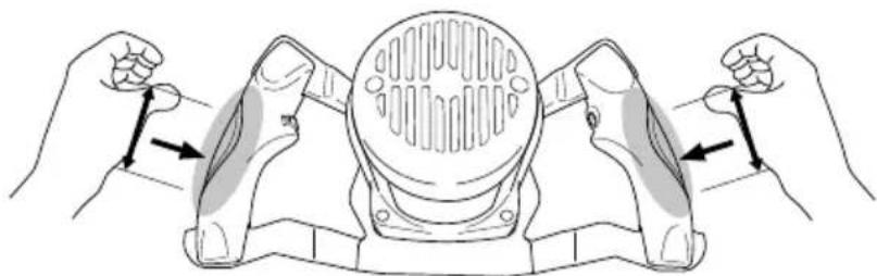
MIXER SAFETY INSTRUCTIONS
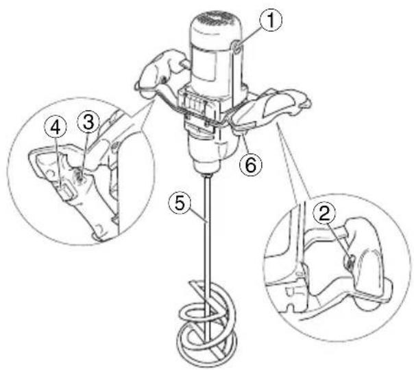
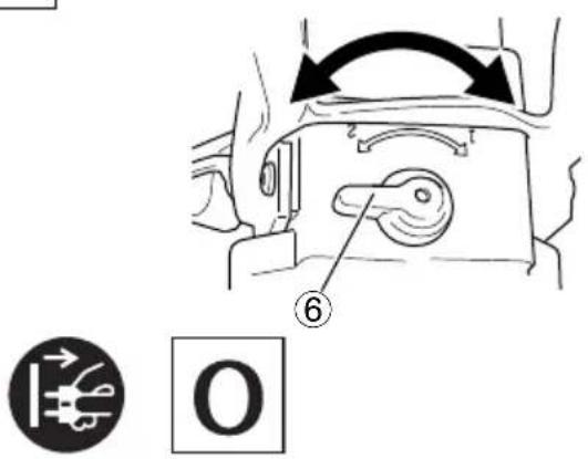
a) Hold the tool with both hands at the intended handles. (Fig. 6)
Loss of control can cause personal injury.
b) Ensure sufficient ventilation when mixing flammable materials to avoid a hazardous atmosphere.
Developing vapour may be inhaled or be ignited by the sparks the power tool produces.
c) Do not mix food.
Power tools and their accessories are not designed for processing food.
d) Keep the cord away from the working area.
The cord may be entangled by the mixer basket.
e) Ensure that the mixing container is placed in a fi rm and secure position.
A container that is not properly secured may move unexpectedly.
f) Ensure that no liquid splashes against the housing of the power tool.
Liquid that has penetrated the power tool can cause damage and lead to electric shock.
g) Follow the instructions and warnings for the material to be mixed.
Material to be mixed may be harmful.
h) If the power tool falls into the material to be mixed, unplug the tool immediately and have the power tool checked by a qualified repair person.
Reaching into the bucket with the tool still plugged in can lead to electric shock.
i) Do not reach into the mixing container with your hands or insert any other objects into it while mixing.
Contact with the mixer basket may lead to serious personal injury.
j) Start up and run down the tool in the mixing container only.
The mixer basket may bend or spin in an uncontrolled manner.
PRECAUTIONS ON USING THE MACHINE
- Do not use the power tool for explosive materials (e.g., easily infl ammable solvents).
Power tools produce sparks which could ignite developing vapours.
- In case the power tool should fall into the material to be stirred, pull the plug immediately and have the power tool checked by an after-sales service agent.
Material that has penetrated the power tool can cause damage and lead to an electric shock.
- When working with the machine, always hold it firmly with both hands and provide for a secure stance.
The power tool is guided more secure with both hands.
- Do not work materials containing asbestos.
Asbestos is considered carcinogenic.
- Take protective measures when dust can develop during working that is harmful to one's health, combustible or explosive.
Example: Some dusts are regarded as carcinogenic. Wear a dust mask and work with dust/chip extraction when connectable.
- Always wait until the machine has come to a complete stop before placing it down.
The tool insert can jam and lead to loss of control over the power tool.
- Never use the machine with a damaged cable. Do not touch the damaged cable and pull the mains plug when the cable is damaged while working.
Damaged cables increase the risk of an electric shock.
-
When operating a mixer with wet material avoid splashes up to the motor part.
-
Connect machines that are used in the open via a residual current device (RCD).
NAMES OF PARTS (Fig. 1 - Fig. 6)
| 1 | Brush cap | 9 | Nut (L) |
| 2 | Speed control dial | 10 | Nut (R) |
| 3 | Lock for ON | 11 | Extension bar (18.5 mm) |
| 4 | Trigger | 12 | Spindle |
| 5 | Stirrer paddle | 13 | Wrench (19 mm) |
| 6 | Gear shift dial | 14 | Wrench (22 mm) |
| 7 | Stirrer (L) | 15 | Wrench (28 mm) |
| 8 | Stirrer (R) |
SYMBOLS
WARNING
The following show symbols used for the machine. Be sure that you understand their meaning before use.
| UM 22VYST / UM 16VST2 / UM 12VST2: Mixer | |
 | To reduce the risk of injury, user must read instruction manual.Only for EU countriesDo not dispose of electric tools together with household waste material!In observance of European Directive 2012/19/EU on waste electrical and electronic equipment and its implementation in accordance with national law, electric tools that have reached the end of their life must be collected separately and returned to an environmentally compatible recycling facility. |
 | Switching ON |
 | Switching OFF |
 | Disconnect mains plug from electrical outlet |
 | Class II tool (Double insulation) |
SPECIFICATIONS
| Model UM 22VYST UM | 16VST2 UM 12VST2 | |||||
| Voltage (by areas)*1 | 230 V~ | |||||
| Power input*1 | 1800 W 1600 W 1200 W | |||||
| Speed change 121212 | ||||||
| No load speed 150 – 300 min-1 | 300 – 650 min-1 | 150 – 300 min-1 | 300 – 650 min-1 | 150 – 300 min-1 | 300 – 650 min-1 | |
| Stirrer paddle 220 mm (135 mm × 2) 160 mm 120 mm | ||||||
| Weight*2 | 6.4 kg 5.7 kg 5.4 kg | |||||
*1 Be sure to check the nameplate on product as it is subject to change by areas.
*2 Weight: According to EPTA-Procedure 01/2014
Electronic control
○ Soft start
Reduces recoil against the operator by managing the number of rotations during startup.
○ 0 Voltage Re-start Protection
The 0 voltage restart protection feature prevents the power tool from restarting after the power has been temporarily cut off during operation.
○ Variable speed
○ Overload protection
This protection feature cuts off the power to the motor in the event of overloading of motor or a conspicuous reduction in rotational speed during operation.
When the overload protection feature has been activated, the motor may stop.
In this case, release the tool switch and eliminate causes of overloading.
After that you can use it again.
NOTE
Due to HiKOKI's continuing program of research and development, the specifications herein are subject to change without prior notice.
STANDARD ACCESSORIES
| UM 22VYST | UM 16VST2 | UM 12VST2 | |
| Stirrer paddle (mm) | 135 × 2 | 160 × 1 | 120 × 1 |
| Extension bar (mm) | — | L185 | — |
Standard accessories are subject to change without notice.
APPLICATIONS
Mixing pulverised building materials such as mortar, plaster, adhesives, as well as solvent-free paint, varnish and similar substances.
PRIOR TO OPERATION
1. Power source
Ensure that the power source to be utilized conforms to the power requirements specified on the product nameplate.
2. Trigger
Ensure that the trigger is in the OFF position. If the plug is connected to a receptacle while the trigger is in the ON position, the power tool will start operating immediately, inviting serious accident.
3. Extension cord
When the work area is removed from the power source, use an extension cord of sufficient thickness and rated capacity. The extension cord should be kept as short as practicable.
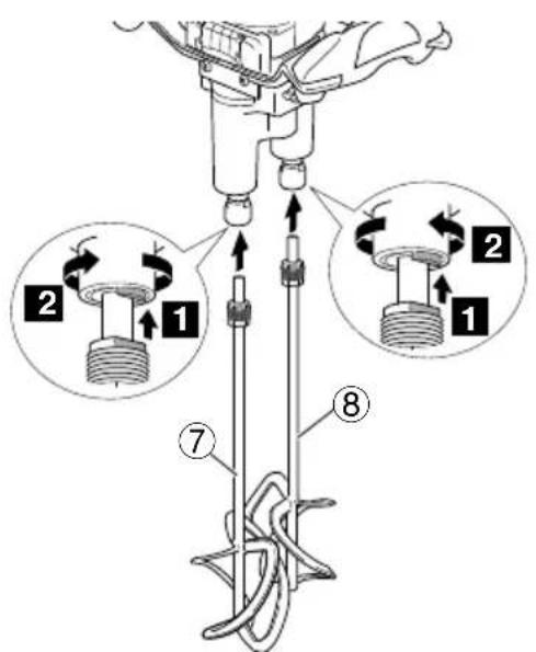
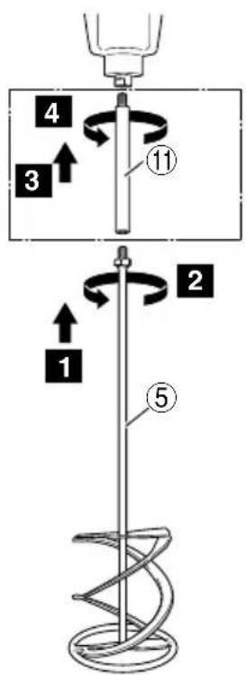
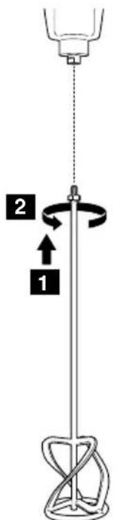
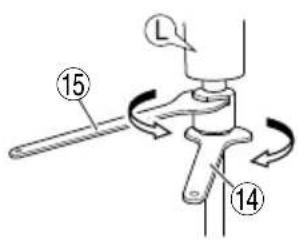
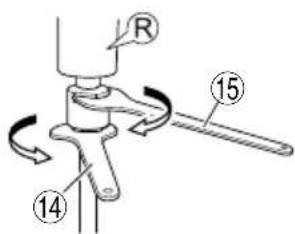
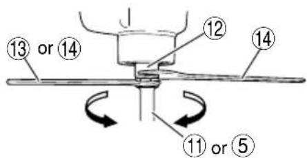
4. Mounting and dismounting of the stirrer paddle (Fig. 2)
CAUTION
To avoid serious accident, ensure the trigger is in the OFF position, and the power source is disconnected. Disconnect the main plug!
(1) Screw the stirrer paddle onto the spindle. Hold the spindle in place with wrench and turn the stirrer paddle with another wrench in the clockwise direction (viewed from the front side). Tighten securely.
A wrench with the measurements below is required. [UM 22VYST: 22 mm, 28 mm] [UM 16VST2: 22 mm × 2, 19 mm (for extension bar)] [UM 12VST2: 22 mm × 2]
(2) The stirrer paddle is disassembled in reverse order.
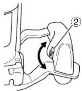
5. High-speed/Low-speed changeover
Prior to changing speed, ensure that the trigger is in the OFF position, and the machine has come to a complete stop.
To change speed, rotate the gear shift dial as indicated by the arrow in Fig. 3. The numeral "1" engraved on the machine body denotes low speed, the numeral "2" denotes high speed.
If it is hard to turn the gear shift dial, turn the spindle slightly in either direction and then turn the gear shift dial again.
HOW TO USE
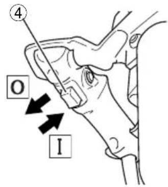
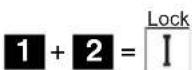
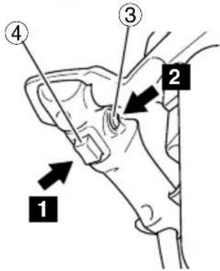
1. Switch operation (Fig. 4)
- When the trigger is depressed, the tool rotates. When the trigger is released, the tool stops.
○ Pulling the trigger and pushing the Lock for ON, it keeps the switched-on condition which is convenient for continuous running. When switching off, the Lock for ON can be disconnected by pulling the trigger again.
2. Adjusting the speed (Fig. 5)
The desired rotation speed can be pre-selected with the speed control dial.
MAINTENANCE AND INSPECTION
The plug must be first pulled out before maintenance and cleaning.
1. Storage and cleaning
When a mixer is not in use store it in dry locations the motor part upwards.
When cleaning a mixer avoid entrance of any water or liquid to the motor part.
2. Inspecting the mounting screws
Regularly inspect all mounting screws and ensure that they are properly tightened. Should any of the screws be loose, retighten them immediately. Failure to do so could result in serious hazard.
3. Maintenance of the motor
The motor unit winding is the very “heart” of the power tool. Exercise due care to ensure the winding does not become damaged and/or wet with oil or water.
4. Inspecting the carbon brushes
The motor employs carbon brushes which are consumable parts. Since an excessively worn carbon brush can result in motor trouble, replace the carbon brushes with new ones having the same carbon brush No.. In addition, always keep carbon brushes clean and ensue that they slide freely within the brush holders.
CAUTION
When replacing the new carbon brushes, always use genuine HiKOKI carbon brushes with the number specified in the drawing.
5. Replacing carbon brushes
Disassemble the brush caps with a slotted-head screwdriver. The carbon brushes can then be easily removed. Contact the HiKOKI Authorized Service Center when repurchasing carbon brushes.
6. Replacing supply cord
If the supply cord of Tool is damaged, the Tool must be returned to HiKOKI Authorized Service Center for the cord to be replaced.
If it becomes necessary to replace the connecting cable, then this is to be undertaken by the manufacturer or his representative in order to avoid any safety risks.
CAUTION
In the operation and maintenance of power tools, the safety regulations and standards prescribed in each country must be observed.
GUARANTEE
We guarantee HiKOKI Power Tools in accordance with statutory/country specific regulation. This guarantee does not cover defects or damage due to misuse, abuse, or normal wear and tear. In case of complaint, please send the Power Tool, undismantled, with the GUARANTEE CERTIFICATE found at the end of this Handling instruction, to a HiKOKI Authorized Service Center.
IMPORTANT
Correct connection of the plug
The wires of the mains lead are coloured in accordance with the following code:
Blue: — Neutral
Brown: — Live
As the colours of the wires in the mains lead of this tool may not correspond with the coloured markings identifying the terminals in your plug proceed as follows:
The wire coloured blue must be connected to the terminal marked with the letter N or coloured black.
The wire coloured brown must be connected to the terminal marked with the letter L or coloured red.
Neither core must be connected to the earth terminal.
NOTE
This requirement is provided according to BRITISH STANDARD 2769: 1984.
Therefore, the letter code and colour code may not be applicable to other markets except United Kingdom.
Information concerning airborne noise and vibration
The measured values were determined according to EN62841 and declared in accordance with ISO 4871.
Measured A-weighted sound power level:
89.4 dB (A) (UM 12VST2)
93.6 dB (A) (UM 16VST2)
97.9 dB (A) (UM 22VYST)
Measured A-weighted sound pressure level:
78.4 dB (A) (UM 12VST2)
82.6 dB (A) (UM 16VST2)
86.9 dB (A) (UM 22VYST)
Uncertainty KpA: 3 dB (A).
Wear hearing protection.
Vibration total values (triax vector sum) determined according to EN62841.
No load:
Vibration emission value a_h=
2.0 2 K = 1.5 m/s 2 (UHMs12VST2)
2.3 ^2 K = 1.5 m/s ^2 (UHMs16VST2)
2.3 ^2 K = 1.5 m/s ^2 (UHMs22VYST)
Uncertainty K = 1.5 m/s ^4
- The stipulated vibration total values and the stipulated noise emission values have been measured according to a standardized test procedure and they can be used to compare one power tool against another.
- The stipulated vibration total values and the stipulated noise emission values can also be used for a preliminary load assessment.
WARNING:
- The vibration and noise emissions generated during actual use of the power tool may deviate from the indicated values, as they will depend on the way in which the power tool is being used, especially with regard to the type of workpiece being processed.
- Try to keep the load caused by the vibrations as low as possible. Wearing gloves when using the tool and limiting working time are examples of measures that can be taken to reduce vibrations. All parts of the operating cycle are to be taken into consideration (e.g. times when the power tool is switched off and those when it is switched on, but is running without a load).
Vibrationsemissionswert ah =
2,0 2 K = 1,5 m/s 2 (bM\$12VST2)
2,3 ^2 K = 1,5 m/s ^2 (bM\$16VST2)
2,3 2 K = 1,5 m/s 2 (UMS22VYST)
2,0 ^2 K = 1,5 m/s ^2 (UHMs12VST2)
2,3 2 K = 1,5 m/s 2 (UHMs16VST2)
2,3 2 K=1,5 m/s 2 (UMS22VYST)
Incertitude K = 1,5 m/s²
2,0 ^2 K = 1,5 m/s ^2 (UHMs12VST2)
2,3 ^2 K = 1,5 m/s ^2 (UHMs16VST2)
2,3 ^2 K = 1,5 m/s ^2 (UHMs22VYST)
2,0 ^2 K = 1,5 m/s ^2 (UHMs12VST2)
2,3 ^2 K = 1,5 m/s ^2 (UVMs16VST2)
2,3 ^2 K = 1,5 m/s ^2 (UHMs22VYST)
2,0 ^2 K = 1,5 m/s ^2 (UHMs12VST2)
2,3 ^2 K = 1.5 m/s ^2 (UHMs16VST2)
2,3 2 K = 1,5 m/s 2 (UIMs22VYST)
Incertidumbre K = 1,5 m/s²
2,0 ^2 K = 1,5 m/s ^2 (UHMs12VST2)
2,3 ^2 K = 1,5 m/s ^2 (UHMs16VST2)
2,3 ^2 K = 1,5 m/s ^2 (UMS22VYST)
Incerteza de K = 1,5 m/s²
VEDLIKEHOLD OG INSPEKSJON
natural_image
Line drawing of a quill pen with inkwell (no text or symbols)| English Português | ||
| GUARANTEE CERTIFICATE1 Model No.2 Serial No.3 Date of Purchase4 Customer Name and Address5 Dealer Name and Address(Please stamp dealer name and address) | CERTIFICADO DE GARANTIA1 Número do modelo2 Número do série3 Data de compra4 Nome e morada do cliente5 Nome e morada do distribuidor(Por favor, carímbe o nome e morada do distribuidor) | |
| Deutsch Svenska | ||
| GARANTIESCHEIN1 Modell-Nr.2 Serien-Nr.3 Kaufdatum4 Name und Anschrift des Kunden5 Name und Anschrift des Händlers(Bitte mit Namen und Anschrift des Handlers abstempeln) | GARANTICERTIFIKAT1 Modellnr2 Serienr3 Inköpsdatum4 Kundens namn och adress5 Försäljarens namn och adress(Stämpla försäljarens namn och adress) | |
| Français Dånsk | ||
| CERTIFICAT DE GARANTIE1 No. de modèle2 No de série3 Date d’achat4 Nom et adresse du client5 Nom et adresse du revendeur(Cachet portant le nom et l’adresse du revendeur) | GARANTIBEVIS1 Modelnummer2 Serienummer3 Købsdato4 Kundes navn og adresse5 Forhandlers navn og adresse(Indsæt stempel med forhandlers navn og adresse) | |
| Italiano Nørsk | ||
| CERTIFICATO DI GARANZIA1 Modello2 N° di serie3 Data di acquisto4 Nome e indirizzo dell’acquirente5 Nome e indirizzo del rivenditore(Si prega di apporre il timbro con questi dati) | GARANTISERTIFIKAT1 Modellnr.2 Serienr.3 Kjøpsdato4 Kundens navn og adresse5 Forhandlerens navn og adresse(Vennligst stemple forhandlerens navn og adresse) | |
| Nederlands Sjomi | ||
| GARANTIEBEWIJS1 Modelnummer2 Serienummer3 Datum van aankoop4 Naam en adres van de gebruiker5 Naam en adres van de handelaar(Stempel a.u.b. naam en adres vande de handelaar) | TAKUUTODISTUS1 Malli nro2 Sarja nro3 Ostopäivämäärä4 Asiakkaan nimi ja osoite5 Myyjän nimi ja osoite(Leimaa myyjän nimi ja osoite) | |
| Español | ||
| CERTIFICADO DE GARANTÍA1 Número de modelo2 Número de serie3 Fecha de adquisición4 Nombre y dirección del cliente5 Nombre y dirección del distribuidor(Se ruega poner el sello del distribuidor con su nombre y dirección) | ||
HiKOKI
| 1 | |
| 2 | |
| 3 | |
| 4 | |
| 5 |
Siemensring 34, 47877 willich, Germany
Tel: +49 2154 49930
Fax: +49 2154 499350
URL: http://www.hikoki-powertools.de
Hikoki Power Tools Netherlands B.V.
Brabanthaven 11, 3433 PJ Nieuwegein, The Netherlands
Tel: +31 30 6084040
Fax: +31 30 6067266
URL: http://www.hikoki-powertools.nl
Hikoki Power Tools (U.K.) Ltd.
Precedent Drive, Rooksley, Milton Keynes, MK 13, 8PJ, United Kingdom
Tel: +44 1908 660663
Fax: +44 1908 606642
URL: http://www.hikoki-powertools.uk
Hikoki Power Tools France S.A.S.
Hikoki Power Tools Belgium N.V./S.A.
Koningin Astridlaan 51, B-1780 Wemmel, Belgium
Tel: +32 2 460 1720
Fax: +32 2 460 2542
URL http://www.hikoki-powertools.be
Hikoki Power Tools Italia S.p.A
Via Piave 35, 36077, Altavilla Vicentina (VI), Italy
Tel: +39 0444 548111
Fax: +39 0444 548110
URL: http://www.hikoki-powertools.it
Hikoki Power Tools Ibérica, S.A.
C/ Puigbarral, 26-28, Pol. Ind. Can Petit, 08227 Terrassa
(Barcelona), Spain
Tel: +34 93 735 6722
Fax: +34 93 735 7442
URL: http://www.hikoki-powertools.es
Kjeller Vest 7, N-2007 Kjeller, Norway
Tel: (+47) 6692 6600
Fax: (+47) 6692 6650
URL: http://www.hikoki-powertools.no
Hikoki Power Tools Sweden AB
Rotebergsvagen 2B SE-192 78 Sollentuna, Sweden
Tel: (+46) 8 598 999 00
Fax: (+46) 8 598 999 40
URL: http://www.hikoki-powertools.se
Hikoki Power Tools Denmark A/S
Lillebaeltsvej 90, 6715 Esbjerg N, Denmark
Tel: (+45) 75 14 32 00
Fax: (+45) 75 14 36 66
URL: http://www.hikoki-powertools.dk
Hikoki Power Tools Finland Oy
Tupalankatu 9, 15680 Lahti, Finland
Tel: (+358) 20 7431 530
Fax: (+358) 20 7431 531
URL: http://www.hikoki-powertools.fi
natural_image
Line drawing of a quill pen with inkwell (no text or symbols)
natural_image
Line drawing of a quill pen with inkwell (no text or symbols)| English Português | ||
| EC DECLARATION OF CONFORMITYWe declare under our sole responsibility that Mixer, identified by type and specific identification code *1), is in conformity with all relevant requirements of the directives *2) and standards *3). Technical file at *4) - See below.The European Standard Manager at the representative office in Europe is authorized to compile the technical file.Deutsch Svenska | DECLARAÇÃO DE CONFORMIDADE CEDeclaramos, sob nossa única e inteira responsabilidade, que Misturador, identificado por tipo e código de identificação específico *1), está em conformidade com todos os requerimentos relevantes das diretivas *2) e normas *3). Ficheiro técnico em *4)-Consulte abaixo.O Gestor de Normas Europeias no escritório de representação na Europa está autorizado a compilar o fi cheiro técnico.A declaração aplica-se aos produtos com marca CE. | |
| EG-KONFORMITÄTSERKLÄRUNGWir erklären in alleiniger Verantwortung, dass das durch den Typ und den spezifischen Identifizierungscode *1) identifizierte Mixgerät allen einschlägigen Bestimmungen der Richtlinien *2) und Normen *3) entspricht. Technische Unterlagen unter *4) - Siehe unten.Die Leitung der repräsentativen Behörde für europäische Normen und Richtlinien ist berechtigt, die technischen Unterlagen zusammenzustellen.Die Erklärung gilt für die an dem Produkt angebrachte CE-Kennzeichnung. | EG-DEKLARATION BETRÄFFANDE LIKEFORMIGHETVi intygar på eget ansvar att denna blandare, identifierad enligt typ och särskild identifikationskod *1), överensstämmer med alla relevanta krav i direktiven *2) och standarderna *3). Teknisk fi i enligt *4) - Se neden.Den europeiska standardansvariga på representationskontoret i Europa är auktoriserad att sammenställa den tekniska fi len.Denna försäkran gäller för produkten med tillhörande CE-märkning. | |
| Français DanskDECLARATION DE CONFORMITE CENous déclarons sous notre entière responsabilité que le Mixeur, identifié par le type et le code d'identification spécifique *1) est en conformité avec toutes les exigences applicables des directives *2) et des normes *3). Dossier technique en *4) - Voir ci-dessous.Le Gestionnaire des normes européennes du bureau de représentation en Europa est autorisé à constituer le dossier technique.Cette déclaration s'applique aux produits désignés CE. | EF-OVERENSSTEMMELSESERKLÆRINGVi erklærer os fuldstændige ansvarlige for, at mikseren, identificeret ved type og specifik identifikationskode *1), er i overensstemmelse med alle relevante krav i direktiverne *2) og standarderne *3). Teknisk fi i *4) - Se nedenfor.Lederen af europæiske standarder på repräsentationskontoret i Europa er bemyndiget til at komplere den tekniske fi l.Erklæringen gælder produktet, der er mærket med CE. | |
| Italiano NorskDICHIARAZIONE DI CONFORMITÀ CEDichiariamo sotto la nostra esclusiva responsabilità che il mixer, identificato dal tipo e dal codice identificativo specifico *1), è conforme a tutti i requisiti pertinenti delle direttive *2) e degli standard *3). Documentazione tecnica presso *4) - Vedere sotto.Il gestore delle norme europee presso l'ufficio di rappresentanza in Europa è autorizzato a compilare il fascicolo tecnico.La dichiarazione è applicabile ai prodotti cui sono applicati i marchi CE. | EF'S ERKLÆRING OM OVERENSSTEMMELSEVi erklærer på eget ansvar at blandeverktøy, identifisert etter type og spesifik identifikasjonskode *1), er i samsvar med alle relevante krav i direktiver *2) og standarder *3). Teknisk fi i under *4) - Se nedenfor.Styreren for europeiske standarder ved representantkontoret i Europa er autorisert til å komplere den tekniske fi len.Erklæringen gjelder for CE-merket på produktet. | |
| Nederlands SupmiEC VERKLARING VAN CONFORMITEITWij verklaren onder onze eigen verantwoordelijkheid dat Mixer, geïdentificeerd door het type en de specifieke identificatiecode*1), voldoet aan alle relevante bepalingen van de richtlijnen*2) en normen*3). Technische documentatie bij*4) - zie onder.De Europese Normen Manager bij de vertegenwoordiging in Europa is gemachtigd om het technisch dossier samen te stellen.Deze verklaring is van toepassing op producten voorzien van de CE-markeringen. | EY-ILMOITUS YHDENMUKAISUUDESTAVakuutamme yksinomaisella vastuullamme, että sekoitin, joka identifioidaan tyypin ja erityisen tunnistuskoodin *1) perusteella, on kaikkien direktiivien *2) ja standardien *3) asiaankuuluvien vaatimusten mukainen. Tekninen tiedosto kohdassa *4) - katso alta.Eurooppalaisten standardien hallintaelin Euroopan edustustossa on valtuutettu kokoamaan teknisen tiedoston.Ilmoitus on sovellettavissa tuotteeseen kiinnitettyyn CE-merkintään. | |
| EspañolDECLARACIÓN DE CONFORMIDAD DE LA CEDeclaramos bajo nuestra única responsabilidad que la Batidora, identificada por tipo y por código de identificación específico *1), está en conformidad con todas las disposiciones correspondientes de las directivas *2) y de las normas *3). Documentación técnica en *4) - Ver a continuación.El Director de Normas Europeas en la oficina de representación en Europa está autorizado para elaborar el expediente técnico.La declaración se aplica al producto con marcas de la CE. | ||
| *1) UM 22VYST C353777RUM 16VST2 C353775RUM 12VST2 C353773R*2) 2006/42/EC, 2014/30/EU, 2011/65/EU*3) EN62841-1:2015EN62841-2-10:2017EN55014-1:2017EN55014-2:2015EN61000-3-2:2014EN61000-3-3:2013 | ||
| *4) Representative office in EuropeHikoki Power Tools Deutschland GmbHSiemensring 34, 47877 Willich, GermanyHead office in JapanKoki Holdings Co., Ltd.Shinagawa Intercity Tower A, 15-1, Konan 2-chome,Minato-ku, Tokyo, Japan | 28. 6. 2019Naoto YamashiroEuropean Standard Manager28. 6. 2019A. NakagawaCorporate Offi cer | |