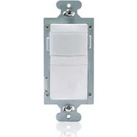
RH250W - Electrical switch LEGRAND - Free user manual and instructions
Find the device manual for free RH250W LEGRAND in PDF.



User questions about RH250W LEGRAND
0 question about this device. Answer the ones you know or ask your own.
Ask a new question about this device
Download the instructions for your Electrical switch in PDF format for free! Find your manual RH250W - LEGRAND and take your electronic device back in hand. On this page are published all the documents necessary for the use of your device. RH250W by LEGRAND.
USER MANUAL RH250W LEGRAND
Incandescent or fluorescent .0-600 Watts
Fan motor 1/6 hp
Time Delay Adjustment 15 sec., 5 min., 15 min., 30 min.
Light Level Adjustment 10 fc to 150 fc
Environment. Indoor use only
Operating Temperature. 32^ to 131^ (0^ to 55^)
Humidity. 95% RH, non-condensing
Tools Needed
Insulated Screwdriver
Wire Strippers
DESCRIPTION AND OPERATION
RH-250 Multi-way Wall Switch Convertible Occupancy Sensors are designed to replace standard single pole and multi-way (3-way, 4-way) switches. They are ideal for any room with multiple entries and any other indoor space where vacancy sensor-based controls with manual ON/OFF capability are desirable.
Like standard switches, you can press the ON/OFF button to turn the light or fan (controlled load) ON and OFF. Unlike standard switches, the RH-250 automatically turns OFF the controlled load after the coverage area has been vacant for a period of time (Time Delay). If motion is detected within 30 seconds after it automatically turns OFF, the RH-250 automatically turns the load back ON.
While the sensor is factory preset as a Vacancy Sensor with manual ON operation, it can be adjusted to work as an occupancy sensor that turns the controlled load ON automatically upon detection of occupancy in the area.
The RH-250 can be wired with up to three additional RH-250s for multi-way Manual/Auto-ON/OFF of one or several loads (up to one load connected to each RH-250). It can also be wired to up to four RH-253 single pole momentary wall switches for multi-way Manual-ON/OFF Automatic-OFF control of one load.
Lighted Switch
To help you locate the RH-250 in a dark room, the amber LED illuminates the ON/OFF button while the controlled load is OFF. When the controlled load is ON, the LED is OFF.
Operating Modes
For multi-way operation of two or more RH-250s, we recommend that the Operating Mode be the same in all sensors related to the same load. This makes it easier to understand the multi-way control operation as well as trouble shooting. There are two operating modes to select from:
MODE 1 Vacancy sensor (Manual-ON/OFF, Auto-OFF): The user must press the ON/OFF button to turn the load ON. The RH-250 keeps the load ON until no motion is detected by any of the related RH-250s for the time delay period. There is also a 30 second reset delay after the automatic shut-off. If motion is detected during this time, the sensor turns the load back ON automatically. After the 30 second reset delay has elapsed, the ON/OFF button must be pressed to turn ON the load.
MODE 2 Occupancy sensor (Auto-ON/OFF with manual control and reset to auto after 5 minutes of vacancy): The load turns ON and OFF automatically based on occupancy detection. Once turned ON the RH-250 keeps the load ON until no motion is detected by any of the related RH-250s for the time delay period. If the load is turned OFF manually, automatic-ON is re-enabled when no motion is detected for 5 minutes. This prevents the load from being turned ON after it was deliberately turned OFF.
Time Delay
The time delay can be selected by the user during set up. It can be adjusted to any of these fixed values: 15 seconds/5 minutes/15 minutes/30 minutes. We recommend that the time delay be the same in all sensors related to the same load. This makes it easier to understand the multi-way control operation as well as trouble shooting. For additional information on how to adjust it, please read the SENSOR ADJUSTMENT & PROGRAMMING section of this installation manual.
Light Level
When the operating mode is set for occupancy sensor, Mode 2 (Auto-ON) this feature prevents the sensor from automatically turning the lights ON if there is already enough light in the area.
In a multi-way application, each sensor monitors the light level at its location. If any sensor related to the load detects motion AND the measured light level in that sensor's area is lower than it's Light Level setting, the load turns ON.
To adjust the light level, please read the SENSOR ADJUSTMENT & PROGRAMMING section of this installation manual.
Coverage Area
The RH-250 has a maximum coverage range of 180 degrees and a coverage area of 600 square feet (56 square meters). The sensor must have a clear and unobstructed view of the coverage area. Objects blocking the sensor's lens may prevent detection thereby causing the light to turn OFF even though someone is in the area.
NOTE: Windows, glass doors, and other transparent barriers will obstruct the sensor's view and prevent detection.
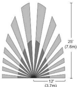
Fig.1: Sensor Coverage Area
INSTALLATION & WIRING
These instructions describe only the 3-way circuit applications. For information about other applications, consult technical support.
1. Prepare the switch box
After the power is turned OFF at the circuit breaker box, remove the existing wall plate and mounting screws. Pull the old switch out from the wall box.
2. Identify the type of circuit
You may connect the RH-250 to a single pole or multi-way circuit. If you are unable to clearly identify some or all of the wires mentioned in this manual, you should consult with a qualified electrician.
In a 3-way circuit (see Fig. 2), two traveler wires connect to both switches. Another wire provides power from the circuit box to one of the switches. A wire connects from one switch to the load. A ground wire may also be connected to a ground terminal on the old switches. A neutral wire should also be present in both wall boxes.
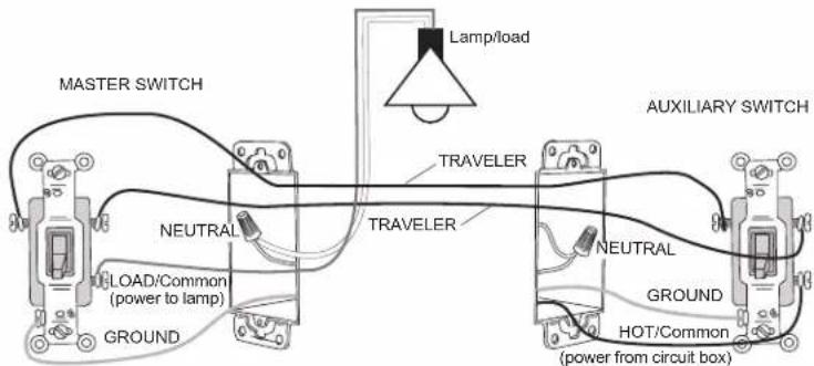
Fig. 2: Typical 3-Way Switch Wiring
CAUTION
For your safety: Connecting a proper ground to the sensor provides protection against electrical shock in the event of certain fault conditions. If a proper ground is not available, consult with a qualified electrician before continuing installation.
3. Prepare the Wires
Tag the wires currently connected to the existing switch so that they can be identified later. Disconnect the wires. Make sure the insulation is stripped off of the wires to expose their copper cores to the length indicated by the "Strip Gauge," in Fig. 3. (approx. 1/2 inch).
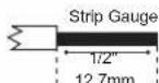
Fig. 3: Wire Stripping
4. Wire the sensor
Twist the existing wires together with the wire leads on the RH-250 sensor(s) as indicated in either step 4a or 4b. Cap wires securely using wire nuts.
a. Wiring two RH-250s in a 3-way configuration
The term "master" designates the RH-250 that connects to the load.
- Connect the green or non-insulated (copper) GROUND wire from the circuit to the green terminal on each RH-250.
- Connect the NEUTRAL wire from the circuit and from the lamp (LOAD) to the white wire on the master RH250.
- Connect the NEUTRAL wire from the circuit in the other wiring box to the white wire on the auxiliary RH-250.
- Connect the power wire from the circuit box (HOT) to the black wire on the auxiliary RH-250 and to the TRAVELER 1 wire.
- Connect the TRAVELER 1 wire from the black wire of the auxiliary RH-250 to the black wire of the master RH-250.
- Connect the lamp power (LOAD) to the red wire on the master RH-250.
- Cap the red wire on the auxiliary RH-250.
- Connect the TRAVELER 2 wire coming from the yellow wire of another RH-250 to the yellow wire of the RH-250 that you are wiring.
b. Wiring one RH-250 and one RH-253 single pole momentary switch for multi-way Manual-ON/OFF single load control.
IMPORTANT: The RH-250 must be installed in the wiring wall box that connects to the load.
- Connect the green or non-insulated (copper) GROUND wire in each wiring box to the green terminal on each RH-250 and RH-253.
- Connect the NEUTRAL wire from the circuit and from the lamp (LOAD) to the white wire on the RH-250.
- Connect the power wire from the circuit box (HOT) to one terminal of the RH-253 single pole momentary wall switch and to the TRAVELER 1 wire.
- Connect the TRAVELER 1 wire coming from the RH-253 wiring box to the black wire of the RH-250.
- Connect the lamp power (LOAD) to the red wire on the RH-250.
-
Connect the TRAVELER 2 wire to the other side of the RH-253 single pole momentary wall switch and to the yellow wire of the RH-250.
-
Put all the new switches into their wall boxes.
Position the RH-250 switch(es) with the lens above the ON/OFF button (lens at top, ON/OFF button at bottom). Use the captive screws on the mounting strap to secure the switches to their wall boxes.
- Restore power to the circuit.
Turn on the breaker or replace the fuse.
- Make any necessary adjustments.
See the SENSOR ADJUSTMENT & PROGRAMMING section for information.
- Install cover plates.
Install industry standard decorator wall switch cover plate (not included)
Initial Power-up
There is an initial warm-up period. If the sensor is in Mode 2 "Automatic ON" it may take up to a minute before the lights turn ON. However, the lights can be turned ON/OFF manually by pressing the "ON/OFF Button" at any time when power is supplied to the unit.
SENSOR ADJUSTMENT & PROGRAMMING
To program the RH-250, you use controls located under the ON/OFF button. The wall switch cover plate must be removed to gain access to the mode button and adjustment trimpots under the ON/OFF button.
- Firmly grasp the side edges of the Lock Bar and gently pull it away from the switch face until it clicks. Do NOT attempt to pull the Lock Bar off of the switch!
- Firmly grasp the side edges of the ON/OFF button. Slide the button downward approximately 1/2 inch to expose the mode button and adjustment trimpots.
For multi-way operation, the Operating Mode and the Time Delay adjustments should be the same in all sensors related to the same load.
Setting up the Operating Mode
Select the operating mode by pressing the Mode button. The amber LED behind the switch button blinks to indicate the selected mode. The blink pattern repeats three times:
- One blink indicates Mode 1 (Vacancy Sensor Operation), Manual-ON/OFF, Auto-OFF
- Two blinks indicates Mode 2 (Occupancy Sensor Operation), Auto-ON/OFF with manual control and reset to auto (after 5 minutes of vacancy)
To change the mode, press the Mode button once to set the unit to mode 1 or press the Mode button twice to set the unit to mode 2. The LED blinks to indicate the selected mode. It repeats the selected mode three times. After that, the unit operates in the indicated mode.
Adjusting the Time Delay
Turn the right trimpot counter-clockwise to reduce the amount of time the lights will remain ON after the last motion detection (minimum = 15 seconds). Turn the same trimpot clockwise to increase this time delay (maximum = 30 minutes). You can only select the following values: 15 seconds/5 minutes/15 minutes/30 minutes.
Warning: Do not overturn the Time Delay adjustment trimpot!
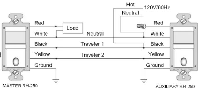
Fig. 5 Step 4a. Reference wiring diagram
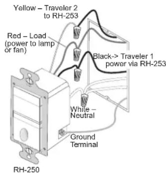

Fig. 6: Step 4b. Sensor orientation and wire connections for 3-way operation with an RH-253 momentary wall switch
To wire up to four RH-253 single pole momentary wall switches to one RH-250, wire them in parallel as shown in the following wiring diagram.
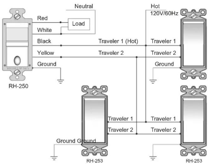
Fig. 7: Step 4b. Reference wiring diagram for multi-way operation with RH-253 momentary wall switches (4 maximum)
ED behind the switch button blinks to indicate the selected mode. The
Warning: Do not overturn the Time Delay adjustment trimpot!
Adjusting the Light Level
This feature is factory set at maximum, so that even the brightest light will not prevent the sensor from turning the load ON when it detects occupancy. If this feature is not needed, leave the light level at maximum, fully clockwise.
The light level must be adjusted when lights would normally be turned OFF because there is enough natural illumination. Each RH-250 may have a different light level setting.
- Set all RH-250s to Mode 1 (Manual-ON) - except for the one that you're adjusting.
- Set the RH-250 you're adjusting so that it is in Mode 2 (Automatic-ON).
- Reduce the time delay to 15 seconds.
- Adjust the Light Level trimpot to minimum (fully counter-clockwise) on the unit that you're adjusting. Move out of the coverage area. Let the sensor time out so lights are OFF and then wait 30 seconds more.
- Without casting a shadow on the sensor, enter the area. The lights should remain OFF. Adjust the Light Level trimpot clockwise in small increments. After each adjustment, wait 5-10 seconds to see if the lights turn ON.
Continue this procedure until the lights turn ON. At this setting the light will not turn ON automatically with occupancy if the light level measured at this sensor is above the current natural illumination.
- Repeat the process (beginning with step 1) for each RH-250 in your multi-way configuration until the Light Level has been adjusted properly in all of them.
- When you have finished adjusting the Light Level of all the RH-250s, return them all to Mode 2.
- Reset the time delay to the desired setting in all units.
Warning: Do not overturn the Light Level adjustment trimpot!
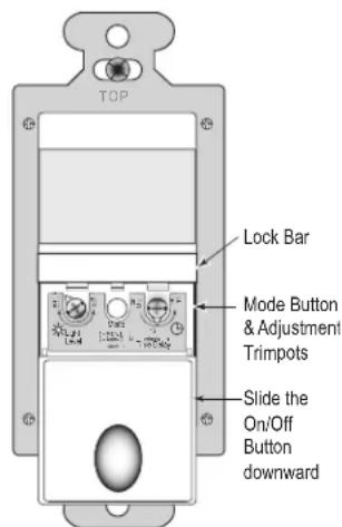
Fig. 8: Sensor Adjustment Controls
TEST MODE
To test the detection coverage:
- Press and hold the ON/OFF button. After 10 seconds the lighted switch turns off. The load turns ON if it was not already ON. The sensor is now in a TEST mode that lasts 5 minutes. (You can end the TEST mode sooner by pressing the ON/OFF button for another 10 seconds). During the TEST mode, the controlled load turns ON for 5 seconds each time the sensor that initiated the TEST mode detects occupancy.
- Move out of the coverage area or stand very still. The controlled load turns OFF after 5 seconds if no motion is detected.
- Move into the coverage area for the unit that initiated the TEST mode. The controlled load turns ON for 5 seconds each time the sensor detects motion. After 5 seconds expire without motion detection, the load turns OFF. The controlled load turns ON automatically with the next motion detection and stays ON for 5 seconds.
- Repeat as necessary to ensure that the desired coverage areas are within detection range.
You can do this test for each RH-250 in your multi-way configuration. So that you can determine the actual coverage area for each multi-way switch individually, only the RH-250 that is in TEST mode will control the load.
TROUBLESHOOTING
Lighted switch is OFF, no load response to ON/OFF button press:
- Make certain that the circuit breaker is on and functioning.
Lighted switch is ON, no load response to ON/OFF button press:
- Check the lamp and/or motor switch on the fan mechanism.
Load will not turn OFF automatically:
- Press ON/OFF button. If the controlled load turns OFF, go to next step.
- The time delay can be set from 15 seconds to 30 minutes. Check the time delay setting for each RH-250 in your multi-way configuration. Ensure that all RH-250s have the same time delay setting.
- Ensure that there is no movement within the coverage area for all the sensors related to the load for the set time delay. Hot air currents and heat radiant devices can cause false detection. Make sure the sensor is at least 6 feet (2 meters) away from devices that are a significant heat source (e.g. heater, heater vent, high wattage light bulb).
Load will not turn ON automatically when the area is occupied and the sensors are in Mode 2 (lighted switch is ON):
- Press ON/OFF button. If the load turns ON, check the Light Level setting. The light level can prevent the sensor from turning ON the load automatically.
- Make sure the sensor lenses are not blocked and that you are within the coverage area of at least one sensor.
If the load does not turn ON when you press the ON/OFF button, check the light bulb and/or motor switch on the fan mechanism.
If load does not respond properly after following troubleshooting, turn OFF power to the circuit then check wire connections or call technical support.
COVER PLATES
Wattstopper RH wall switches fit behind industry standard decorator style switch cover plates.
DESCRIPTION ET FONCTIONNEMENT
INFORMATIONS RELATIVES A LA GARANTIE
INFORMACION DE LA GARANTIA
Wattstopper warranties its products to be free of defects in materials and workmanship for a period of five (5) years. There are no obligations or liabilities on the part of Wattstopper for consequential damages arising out of, or in connection with, the use or performance of this product or other indirect damages with respect to loss of property, revenue or profit, or cost of removal, installation or reinstallation.