
364659-02 - Loudspeaker LEGRAND - Free user manual and instructions
Find the device manual for free 364659-02 LEGRAND in PDF.


| Product Type | Wireless Speaker |
| Brand | Legrand |
| Model | 364659-02 |
| Dimensions (H x W x D) | 200 mm x 100 mm x 100 mm |
| Weight | 0.5 kg |
| Power Supply | USB-C (5V, 1A) or Built-in rechargeable battery |
| Battery Capacity | 2000 mAh |
| Battery Life | Up to 8 hours (at 50% volume) |
| Connectivity | Bluetooth 5.0 |
| Speaker Type | Full-range driver |
| Output Power | 5W RMS |
| Frequency Response | 100 Hz - 20 kHz |
| Impedance | 4 ohms |
| Waterproof Rating | IPX5 (splash resistant) |
| Hands-free Calling | Built-in microphone |
| Controls | Power, Volume, Play/Pause, Next/Previous track |
| Indicators | LED for power and Bluetooth status |
| Compatibility | Smartphones, tablets, computers with Bluetooth |
| Box Contents | Speaker, USB charging cable, User manual |
| Maintenance & Cleaning | Clean with a soft, dry cloth. Avoid solvents. |
| Safety | Do not expose to extreme temperatures or moisture. Keep away from children. |
| Spare Parts & Repairability | Contact Legrand support for battery replacement. |
| Warranty | 2 years |
Frequently Asked Questions - 364659-02 LEGRAND
User questions about 364659-02 LEGRAND
0 question about this device. Answer the ones you know or ask your own.
Ask a new question about this device
Download the instructions for your Loudspeaker in PDF format for free! Find your manual 364659-02 - LEGRAND and take your electronic device back in hand. On this page are published all the documents necessary for the use of your device. 364659-02 by LEGRAND.
USER MANUAL 364659-02 LEGRAND
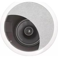
On-Q/Legrand offers both in-ceiling and in-wall styles of evōQ™ 3000 speakers. These two styles encompass two (2) sizes and five (5) part numbers (as shown in Figure 1 to the right). The speakers are optimized for audio distribution (central sound). All models are 2-way speakers that feature Mica-Fiber woofers and PEI (Polyetherimide) Mylar tweeters. These speakers come with dual templates with center markings and paint rings. Optional speaker pre-construction brackets are available for all models.
(*P/N 364658-01, 6.5" In-Ceiling Dual Voice Coil Speaker, is for reference only and NOT part of this instruction sheet.)
Disclaimer: Make sure you are in compliance with local building codes before installing these speakers. On-Q evōQ™ 3000 In-Wall and In-Ceiling Speakers are suitable for moisture rich environments such as bathrooms, saunas and outdoor applications.
In-Ceiling Style (shown w/o grill)

natural_image
Close-up of a speaker cone with blue inner layer and black outer ring (no text or symbols)6.5" – P/N 364654-02 (pair) 8" – P/N 364655-02 (pair) * 6.5" Dual Voice Coil – P/N 364658-01 (each)
In-Wall Style (shown w/o grill)

natural_image
Close-up of a speaker with purple and blue tones, no visible text or symbols6.5" – P/N 364656-02 (pair) 8" – P/N 364657-02 (pair)
Figure 1
2. Description
The On-Q/Legrand evōQ™ 3000 speakers are made of a tough semi-flexible plastic frames that feature a built in foam gasket to minimize vibration and maximize seal-ability. They also feature a perforated metal grill with an acoustically transparent scrim cloth to enhance the speakers appearance once installed. All evóQ speakers, except sub woofers, are paint-able. They also come with painting shields to protect the drivers while painting. These speakers are suitable for moisture rich environments. They also feature flip out tabs for easy installation and removal.
3. Installation
Installation of the evōQ™ 3000 speakers is best accomplished at multiple times during new construction, at "Rough-in" before the drywall is installed, and at "Trim-out" after the drywall is installed and painted.
A. "Rough-in" steps:
NOTE: It is recommended that a minimum of 16 gauge, 2 conductor wire be used for most applications from the amplifier or volume control to the speaker. Different gauges can, and should, be used based upon the distance of the intended run or quality of installation (see Figure 2).
NOTE: All On-Q/Legrand lyriQ™ Audio components accommodate wire gauges from 18 to 14.
Speaker Wire Gauge Selection Chart
| Distance | Gauge |
| <10 Feet 18 | |
| 10-50 Feet 16 | |
| >50 Feet 14 |
Figure 2
-
Run x/2 conductor (x=gauge preference) stranded speaker wire from the distribution/volume control to the speaker location (pre-wiring).
-
If an On-Q Speaker Pre-Construction Bracket is to be used, skip to Step "5" and refer to IS-0243 for detailed instructions.
- If pre-wiring without using the On-Q Pre-Construction Speaker Brackets, leave 4 to 6 feet of wire at the speakers intended location. Use a strip of cardboard stapled to the joints/studs with a hole through it as a wire place holder for the drywall installers if installation of the speakers is intended (see Figure 3).
- After drywall and/or painting is complete, push wire through hole, center template over hole, mark with a pencil and cut out with a dry-wall knife.
- When using the On-Q Pre-Construction Bracket (see Figure 4), leave a coil of speaker wire on top of the bracket coiled around the speaker mounting hole. There are clips on the corner of the bracket to secure the speaker wire. Leave enough speaker wire to be able to pull the wire through the bracket and comfortably connect the wire to the speaker after the drywall is installed. Strip off 3 inches or so of the speaker cable jacket to expose the positive and negative insulated wires. Strip 3/8-1/2 inch of insulation off of these conductors.
- It is recommended to place insulation behind the speaker to provide some damping for the woofer driver. This will yield the best possible sound. On-Q recommends using poly-encapsulated insulation such as Johns Manville Comfort Therm®. If a defined, consistent sound is desired from both speakers in a space, blocking can be installed to yield the ideal cubic footage for each driver. Insulation would then be put in this space during speaker installation. Refer to blocking chart for details.
- If installing speakers in a space with an attic above it is recommended that the speakers be boxed in with 1/2 inch MDF (medium density fiber board) or plywood with insulation installed. This will provide a defined acoustic space and protect the speaker. The best possible sound will be achieved by doing this. Refer to the blocking chart for details.

Figure 3

Figure 4
Note: Make sure you are in compliance with local building codes before installing this speaker in an attic space.
B. "Trim-out" steps:
- After drywall and/or painting is complete, push the speaker wire through hole, center template over hole, mark with a pencil and cut out with a dry-wall knife.
- Hold the speaker with one hand, (if speaker grill is off, pay careful attention not to push on the woofer's cone, this can cause permanent contortion of the voice coil, thus producing a mechanical rubbing sound or speaker failure), push in the speaker terminal connectors and insert wires; remove speaker grill. Be sure to have the positive wire in the RED terminal and the negative wire in the BLACK terminal.
NOTE: Wiring both speakers identically as the above instruction states will yield speakers that are “in phase”. If one speaker is wired opposite of the other, the speakers will be “out of phase” with one another. If the speakers are “out of phase” the sound might appear smeared (canned) and a significant loss of bass might be noticeable due to phase cancellation. Make sure every installed speaker is correctly phased.
3 Use one hand to push the speaker into the cut out (again, pay careful attention not to push on the woofer's cone, this can cause permanent contortion of the voice coil, thus producing mechanical rubbing sound or speaker failure) and the other to turn the screws that engage the installation tabs (see Figure 5). Tighten the tabs in a cross or X-pattern until "snug". Be careful not to over tighten the tabs or damage could result. The speaker should appear flush to the surface.
NOTE: If using a cordless drill/screwdriver, it is suggested that the screws be turned until almost tight, then finish tightening via a hand screwdriver.
NOTE: A strip of grill adhesive is provided to more securely attach the speaker grills on final installation. Simply insert several short strips evenly around the grill slot prior to insalling the grill cover.
evōQ™ Speaker Blocking Chart
| 6.5" Speaker (0.7 CuFt) Blocking Distance |
| 16" on Center, 2x4 24.00" |
| 16" on Center, 2x6 15.25" |
| 16" on Center, 2x8 11.50" |
| 16" on Center, 2x10 9.00" |
| 16" on Center, 2x12 7.50" |
| 24" on Center, 2x4 15.50" |
| 24" on Center, 2x6 10.00" |
| 8" Speaker (2.1 CuFt) Blocking Distance |
| 16" on Center, 2x4 71.50" |
| 16" on Center, 2x6 45.50" |
| 16" on Center, 2x8 34.50" |
| 16" on Center, 2x10 27.00" |
| 16" on Center, 2x12 22.25" |
| 24" on Center, 2x4 46.00" |
| 24" on Center, 2x6 29.50" |

natural_image
Line drawing of a hand using a tool to adjust or install a component inside a speaker ring (no text or symbols)Figure 5
Speaker Specifications
| evōQTM 3000 | evōQTM 3000 | evōQTM 3000 | evōQTM 3000 | |
| Size/Type 6.5" In-Ceiling 6.5" In-Wall 8" In-Ceiling 8" In-Wall | ||||
| Efficiency | 91dB | 91dB | 91dB | 91dB |
| Power (RMS/Peak) | 50W/100W | 50W/100W | 75W/150W | 75W/150W |
| Frequency Response | 60-20K | 60-20K | 50-20K | 50-20K |
| Woofer Type | Mica Fiber | Mica Fiber | Mica Fiber | Mica Fiber |
| Tweeter Type | PEI Mylar | PEI Mylar | PEI Mylar | PEI Mylar |
| Drywall Hole Size | 7.75" dia. | 7.5" x 10.75" | 9.5" dia. | 8.75" x 12.75" |

Brand : LEGRAND
Model : 364659-02
Category : Loudspeaker