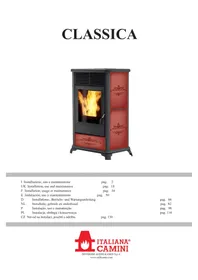
CLASSICA - Wood stove EDILKAMIN - Free user manual and instructions
Find the device manual for free CLASSICA EDILKAMIN in PDF.


| Product Type | Pellet Stove |
| Brand | Edilkamin |
| Model | CLASSICA |
| Fuel | Wood pellets (pellets) Ø 6 mm, max. 40 mm long, humidity ≤ 8% |
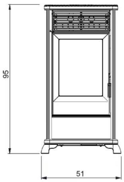
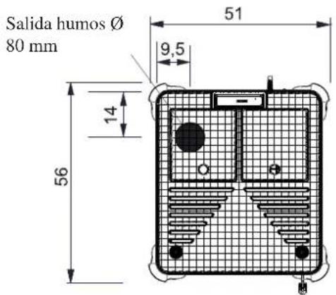
| Dimensions (H x W x D) | 95 x 56 x 51 cm (approximate) |
| Weight (with packaging) | 151 kg |
| Power supply | 230 V ~ 50 Hz, average power consumption 120 W, ignition 320 W |
| Heat output | Nominal: 8 kW; Reduced: 2.4 kW |
| Efficiency | Nominal: 90.1%; Reduced: 94.67% |
| Autonomy | From 7 h (nominal) to 24 h (reduced) |
| Heated volume | 210 m³ (according to insulation compliant with Law 10/91) |
| Hopper capacity | 15 kg |
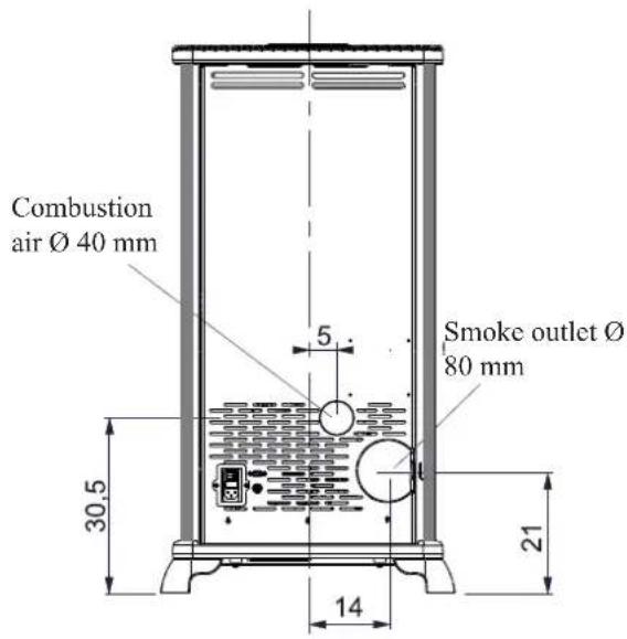
| Smoke outlet diameter | 80 mm (male) |
| Air intake diameter | 40 mm (male) |
| Minimum draft | Nominal: 12 Pa; Reduced: 5 Pa |
| Flue gas temperature | Nominal: 174 °C; Reduced: 81 °C |
| Safety devices | Thermocouple, differential pressure switch, safety thermostat |
| Maintenance | Daily: clean crucible and ash drawer; Weekly: clean upper part; Monthly: clean flue pipe; Yearly: by Technical Assistance Centre (TAC) |
| Spare parts and options | Remote control (code 633280), telephone dialer (code 762210), serial cable (code 640560), glove, spatula, Glasskamin (code 155240) |
| General information | Warranty conditional on commissioning by an approved TAC. Compliant with EU directives 305/2011 and standard EN 14785. |
Frequently Asked Questions - CLASSICA EDILKAMIN
User questions about CLASSICA EDILKAMIN
0 question about this device. Answer the ones you know or ask your own.
Ask a new question about this device
Download the instructions for your Wood stove in PDF format for free! Find your manual CLASSICA - EDILKAMIN and take your electronic device back in hand. On this page are published all the documents necessary for the use of your device. CLASSICA by EDILKAMIN.
USER MANUAL CLASSICA EDILKAMIN
natural_image
Red and black ornate box with flame inside a steam stove (no text or symbols visible)UK Installation, use and maintenance
F Installation, usage et maintenance
natural_image
Technical line drawing of a vertical shelf or enclosure unit with labeled dimensions (95 and 56), no text or symbols present.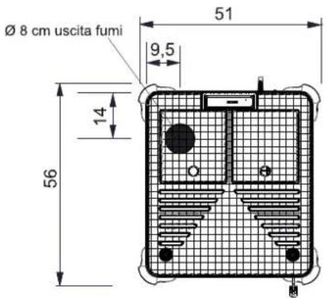
CARATTERISTICHE
PORTA SERIALE
natural_image
Exterior view of a modern office building (no signage)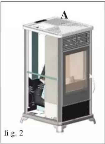
natural_image
Illustration of a small industrial machine with internal components and labeled section A (no text or symbols on the device itself)USCITA FUMI
natural_image
3D diagram of a portable energy storage unit with labeled components (G and fig. 3), no readable text or symbols beyond labels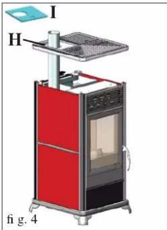
natural_image
Illustration of a red and black portable stove with labeled component A, shown in 3D style (no text or symbols on the device itself)natural_image
3D rendering of a portable electric heater with visible internal components and ventilation grille (no text or symbols)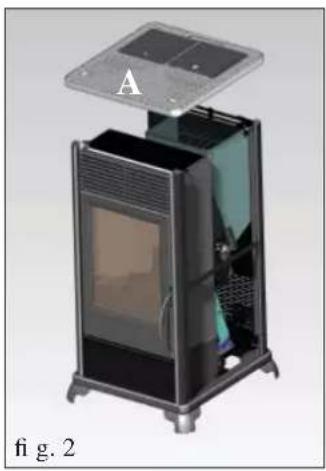
natural_image
Exterior view of a modern office building (no signage)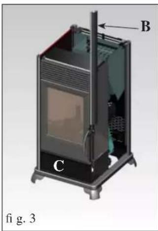
natural_image
3D diagram of a device with labeled components A, B, and C, showing internal structure without any text or symbols.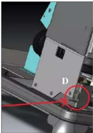
natural_image
Close-up of a mechanical assembly with labeled component D and red annotation arrow (no readable text or symbols)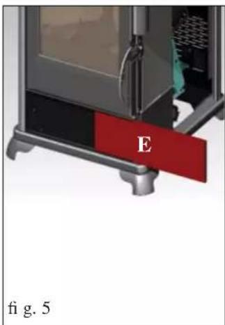
natural_image
Exterior view of a portable electric heater unit (no signage or text visible)natural_image
3D rendering of a white and black industrial machine with ventilation grilles and a lid (no text or symbols visible)fig.1

natural_image
3D rendering of a mechanical device with a bucket and lid, labeled '1' (no text or symbols on the main diagram)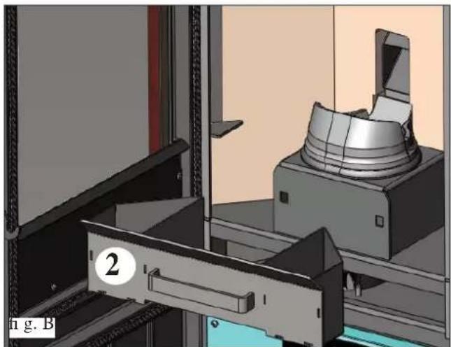
natural_image
3D mechanical assembly diagram showing a clamping device and housing (no text or symbols visible)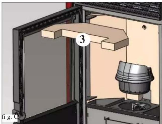
natural_image
3D technical diagram of a mechanical assembly with labeled component (3), showing internal components and housing (no readable text or symbols)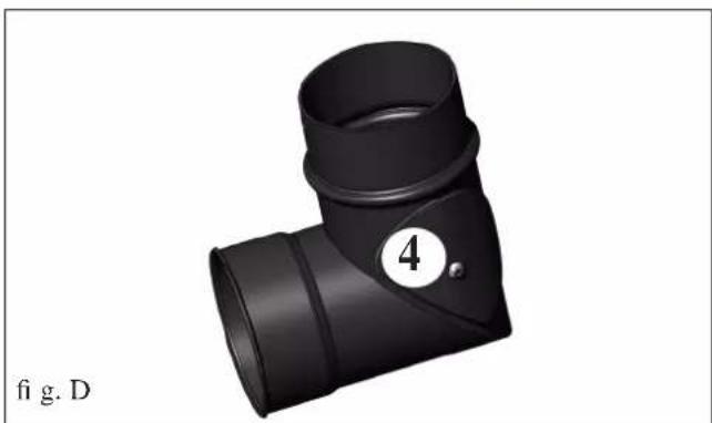
natural_image
3D rendering of a black T-shaped pipe fitting with a numbered circle highlighting part 4 (no text or symbols on the object itself)MANUTENZIONE
natural_image
3D rendering of a mechanical assembly with a cylindrical component mounted on a base, shown in a view from an open frame (no text or symbols visible)fig.2
CONSIGLI PER POSSIBILI INCONVENIENTI
natural_image
Black and white photo of a vacuum cleaner with attached hose and pipe (no visible text or symbols)Bidone aspiracenere
Thank you buying one of our products and congratulations.
Before you start using it, we suggest you read this technical information sheet carefully: it will help you get the best use out of the product and ensure that you always use it in complete safety.
For any further information or requirements, please contact the DEALER where you bought the product or visit our website www.edilkamin.com and see the DEALERS section.
NOTE
- After removing the product from the packaging, check that the contents are intact and complete (flue cover, elbow joint complete with band, casing, guarantee booklet, glove, technical information sheet, spatula, dehumidifying salts).
In the case of anomaly, please contact the dealer where you bought the product immediately, presenting a copy of the guarantee booklet and the official purchase receipt or invoice.
- Starting up/testing
This must be carried out by an EDILKAMIN authorised Technical Assistance Centre (TAC) otherwise the guarantee shall not be effective. The start-up as described by standard UNI 10683 consists of a series of checks carried out when the stove is completely installed to ensure the correct functioning of the system and compliance with standards.
The nearest Assistance Centre can be found by telephoning the toll-free number or by visiting the site www.edilkamin.com.
- the manufacturer shall accept no liability whatsoever from any damage deriving from use in the case of incorrect installation, incorrect maintenance or incorrect use of the product.
- the warranty number necessary for identifying the stove, is indicated:
-on the upper part of the packaging
- in the guarantee booklet placed inside the combustion chamber
- on the plate affi xed to the rear part of the product;
This documentation must be kept for identification, together with the official purchase receipt or invoice. This data must be given when you ask for information and must be made available in the case of any maintenance work;
- the details presented are graphically and geometrically indicative.
The undersigned EDILKAMIN S.p.A. with registered head office at Via Vincenzo Monti 47 - 20123 Milan - Italy - tax code and VAT no. 00192220192
The pellet stove illustrated below conforms to Regulation EU 305/2011 (CPR) and to the harmonised European Standard EN 14785:2006
The PELLET stove bearing the trademark ITALIANA CAMINI, specifically named CLASSICA
Year of manufacture: Ref. Data nameplate Declaration of performance (DoP - EK 067): Ref. data tag plate
It is also declared that:
the wood pellet burning stove CLASSICA complies with the requirements of the European directives:
2006/95/EEC - Low voltage directive
2004/108/EEC - Electromagnetic compatibility directive
EDILKAMIN S.p.A. declines all responsibility for the malfunctioning of a product in the case of replacement, assembly and/or modifications not carried out EDILKAMIN personnel and without the latter's authorisation.
The stove produces hot air using wood pellets as fuel, with electronically controlled combustion.
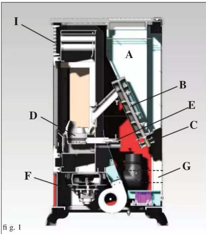
Hereunder is the explanation of its functions (the letters refer to figure 1).
The fuel (pellets) is taken from the hopper (A) and, using a screw (B) operated by a gear motor (C), is sent to the crucible (D).
The pellets are lit by hot air produced by an electrical element (E) sucked into the crucible through a smoke extractor fan (F).
The smoke produced by combustion is extracted from the combustion chamber by the same fan (F) and expelled from the vent (G) which can be connected to the back or the top of the stove (see page 24).
The combustion chamber, with base and ceiling in Vermiculite, closed at the front by a door in ceramic glass.
The quantity of fuel, the extraction of the smoke and the input of air for combustion are regulated by a motherboard equipped with software, to obtain a high combustion yield and low emissions.
The stove has a serial socket for optional wire connection (code 640560) to remote controlled ignition devices (chrono-thermostats etc.).
The ceramic outer casing is available in three colour variants: burgundy, leather and parchment.
SAFETY INFORMATION
The stove is designed to heat, through automatic pellet combustion in the hearth, the room where it is installed, both by radiation and the air that comes out of the front grille (I).
• The appliance is not designed to be used by people, including children, with reduced physical, sensorial or mental abilities. Children must be supervised to ensure they do not play with the appliance.
- The main risks that may derive from using the stove pertain to non-compliance with installation instructions, direct contact with live electrical parts (internal), contact with the fire or hot parts (glass, pipes, hot air output), when extraneous substances or non-recommended fuel are introduced, or due to incorrect maintenance or by repeatedly pressing the ignition button without having emptied the crucible.
- Only use certified, high quality, 6 mm diameter wooden pellets for fuel.
- Should components fail, the stoves are equipped with safety devices that guarantee automatic shutdown. These are activated without any intervention required.
- In order to function correctly, the stove must be installed in accordance with the instructions given herein and the door must not be opened during operation: combustion is fully automatic and requires no intervention.
- Under no circumstances should any foreign substances be entered into the hearth or hopper.
- Do not use fl ammable products to clean the smoke channel (the fl ue section connecting the stove smoke outlet to the chimney fl ue).
• The hearth and hopper parts must only be cleaned when COLD.
• The glass can be cleaned when COLD with a suitable product (e.g. GlassKamin Edilkamin) and a cloth.
- Make sure the stove is installed and ignited the first time by Edilkamin-qualified CAT personnel (technical assistance centre) in accordance with the instructions provided here within; this is an essential requirement for the validation of the guarantee.
- When the stove is in operation, the exhaust pipes and door become very hot (do not touch without wearing the thermal glove).
- Do not place anything, which is not heat resistant near the stove.
- NEVER use liquid fuel to ignite the stove or rekindle the embers.
- Do not obstruct the ventilation apertures in the room where the stove is installed, nor the air inlets of the stove itself.
- Do not wet the stove and do not go near electrical parts with wet hands.
- Do not use reducers on the smoke exhaust pipes.
- The stove must be installed in a room that is suitable for fi re prevention and equipped with all that is required (power and air supply and outlets) for the stove to function correctly and safely.
- If it is necessary to clean the fl ue please remove the heart vermiculite stove removing the fi ns.
• SHOULD IGNITION FAIL, DO NOT RE-IGNITE UNTIL YOU HAVE EMPTIED THE COMBUSTION CHAMBER.
FRONT BACK
SIDE SYSTEM
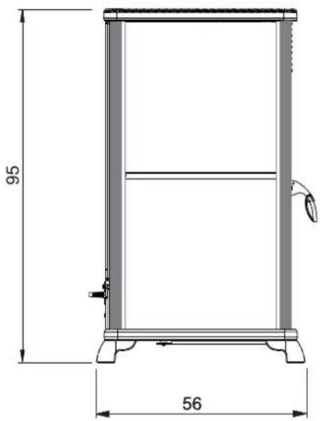
natural_image
Technical line drawing of a vertical shelf or stand with labeled dimensions (95 and 56), no text or symbols present.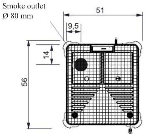
SERIAL PORT
The stove has a serial port RS232, to which an optional on-off control device, such as an environment thermostat, can be installed by the TAC using a special wire (code 640560).
BACKUP BATTERY
The motherboard has a backup battery (type CR 2032, 3 volts).
Failure of the battery is due to normal wear and tear (and is not a manufacturing defect).
For more information, contact the TAC which carried out the first ignition.
SAFETY DEVICES
• THERMOCOUPLE:
Positioned on the smoke discharge, it measures the temperature.
According to the set parameters, it controls ignition, operation and switching off.
• DIFFERENTIAL PRESSURE SWITCH:
Positioned in the smoke-aspiration area, it is triggered in the case of a depression in the circuit (e.g. obstructed flue).
• SAFETY THERMOSTAT:
This intervenes if the temperature inside the stove is too high.
It blocks pellet loading causing the stove to go out.
CHARACTERISTICS
| THERMO TECHNICAL CHARACTERISTICS according to EN 14785 | |||
| Nominal power Reduced power | |||
| Heat output 8 2,4 kW | |||
| Yield / Effi ciency 90,1 94,67 % | |||
| Emissions CO 13% O_2 | 0,019 0,035 % | ||
| Fume temperature 174 81 °C | |||
| Fuel consumption | 1,8 0,5 kg/h | ||
| Hopper capacity | 15 | kg | |
| Minimum draught | 12 - 5 | 10 - 3 | Pa |
| Autonomy | 7 | 24 | ore |
| Heatable volume * | 210 | m^3 | |
| Smoke outlet pipe diameter (male) | 80 | mm | |
| Air intake pipe diameter (male) | 40 | mm | |
| Weight including packaging | 151 | kg | |
| TECHNICAL DATA FOR THE DIMENSIONING OF THE FLUE | |||
| Nominal power Reduced power | |||
| Heat output 8 2,4 kW | |||
| Temperature of fumes on exit from the discharge pipe | 209 97 | °C | |
| Minimum draught | 0 - 5 | Pa | |
| Fume flow capacity | 5,4 | 2,4 | g/s |
* The heatable room dimensions are calculated on the basis of home insulation in compliance with Italian law 10/91, and subsequent changes together with an expected heat output of 33Kcal / m^3 per hour.
| ELECTRICAL CHARACTERISTICS | ||
| Power supply | 230Vac +/- 10% 50 Hz | |
| Average power consumption | 120 W | |
| Power consumption during ignition | 320 W | |
| Protection on electronic circuit board | Fusibile 2AT, 250 Vac | |
N.B.
1) keep in mind that external devices can cause interference to the operation of the circuit board.
2) warning: activity on live components, maintenance and/or checks must be carried out by qualified personnel.
(before carrying out any maintenance, disconnect the appliance from the mains electricity)
The above data are indicative and are those resulting during certification on the part of the notified body.
EDILKAMIN s.p.a. reserves the right to change the products at its discretion without notice.
All local and national laws and European standards must be met when installing and using the appliance. In Italy, refer to the UNI 10683 standard, as well as any regional or local health-authority regulations.
It is necessary to refer to regulations in force in each country. If installing in an apartment building, check with the management company first.
VERIFY COMPATIBILITY WITH OTHER DEVICES
In Italy the stove MUST NOT be installed in the same space as type B gas heating equipment (e.g. gas boilers, stoves, and equipment served by an extraction hood) as the stove may cause a vacuum in the space which may compromise or influence how these units work.
VERIFYTHE POWER SUPPLY CONNECTION
(the plug must be accessible)
The stove is supplied with a power cable that is to be connected to a 230V 50 Hz socket, preferably fitted with a magnetothermic switch. Voltage variations exceeding 10% can damage the stove (unless already installed, an appropriate differential switch must be fitted). The electrical system must comply with the law; particularly verify the efficiency of the earthing system. The power line must have a suitable cross-section for the stove's power. An inadequate earthing system can cause anomalies for which Edilkamin cannot be held liable.
FIRE PREVENTION SAFETY DISTANCES
The stove must be installed in compliance with the following safety conditions:
- minimum distance from fl ammable materials around the sides and back of the stove: 20 cm
- fl ammable materials must not be placed less than 80 cm from the front of the stove.
If it is not possible to comply with the above-mentioned distances, technical and construction-related provisions must be taken to prevent fire hazards.
If connected to wooden walls or other flammable materials, the smoke exhaust pipe must be insulated.
AIR INTAKE
The room where the stove is located must have an air intake with cross section of at least 80cm^2 to ensure replenishment of the air consumed by combustion.
Alternatively, the stove air may be taken directly from outside through a 4 cm steel extension of the pipe.
In this case, there may be condensation problems and it is necessary to protect the air intake with a grille, which must have a freesection of at least 12 cm ^4 .
The pipe must be less than 1 metre long and have no bends. It must end with section at 90^ facing downwards or be fitted with a wind guard. In any case all the way air intake duct must be a free section of at least 12 cm^2 .
The external terminal of the air inlet channel must be protected with an anti-insect netting that does not reduce the 12 cm^2 through passage.
SMOKE OUTLET
The stove must have its own smoke outlet (the smoke cannot be discharged into a smoke flue used by other devices).
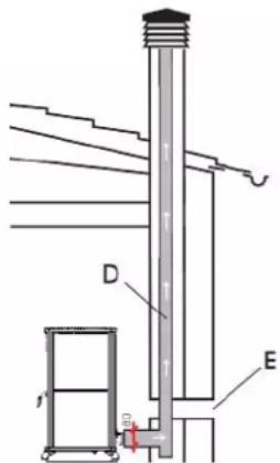
The smoke is discharged through the 8 cm diameter outlet at the back or top of the stove. The smoke outlet must be connected to outside by means of suitable steel pipes EN 1856 certified. The pipe must be hermetically sealed.
The material used to seal and if necessary insulate the pipes, must be resistant to high temperatures (high temperature silicone or mastic). The only horizontal section allowed may be up to 2 m long up to three 90° bends (in relation to the vertical). A vertical section of at least 1.5 m and an anti-wind terminal is necessary (if the discharge outlet is not in a chimney flue - reference UNI 10683).
The vertical duct can be internal or external. If the smoke channel is outside, it must be appropriately insulated. If the smoke channel is fitted inside a chimney flue, the latter must be suitable for solid fuel. If it is wider than 150 mm in diameter it must be improved by entering a pipe that has a suitable cross-section and is made of suitable material (e.g. 80 mm diameter steel). All sections of the smoke duct must be accessible for inspection. The chimney pots and smoke ducts connected to the solid fuel appliances must be cleaned once a year (verify whether a specific legislation exists in your country).
Failure to regularly inspect and clean the stove increases the probability of a fi re occurring in the chimney pot. In that case, proceed as follows: Do not use water to extinguish the fi re; Empty the pellet hopper; Contact specialist personnel before reigniting the stove. The stove is designed to work under any weather conditions. In case of particular conditions, such as strong wind, the safety system may be activated, which results in the stove being extinguished. If this happens, do not operate the stove with the safety devices disabled. If the problem persists, contact our Technical Service Department.
TYPICAL EXAMPLES
Fig. 1
Fig.
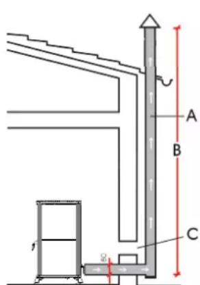
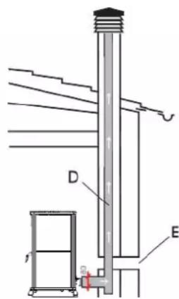
A: insulated steel fl ue
B: minimum height of 1.5 m and in any case above the height of the roof gutter
C-E: air intake from inside room (minimum internal section: 80 cm²)
D: steel flue, inside existing brick-built chimney.
CHIMNEY POT
The main characteristics are:
- an internal cross-section at the base, which is the same as that of the chimney fl ue
- an outlet cross-section which is no smaller than twice that of the chimney fl ue
- its position must be high enough to catch the wind and avoid downdraft areas in turbulent wind, it must be high enough to catch the wind and avoid downdraft areas in turbulent wind.
INSTALLATION
natural_image
Exterior view of a modern office building (no signage)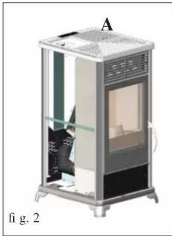
natural_image
Cross-sectional diagram of a mechanical device labeled 'A', showing internal components and structural elements (no text or symbols beyond label)SMOKE OUTPUT
CLASSICA is designed for the connection of the flue at the top, back of the stove.
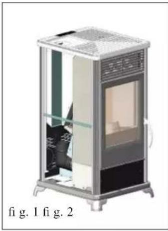
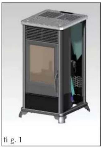
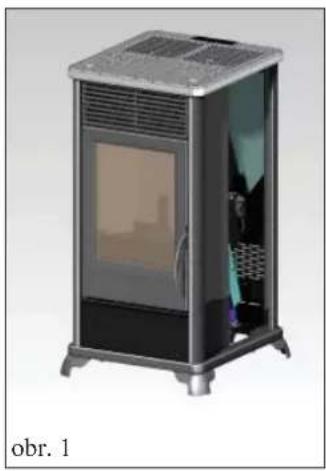
Illustration 1 shows how the stove will appear once it has been unpacked.
To connect the flue from the back it is necessary to remove the elbow junction
To connect the smoke outlet at the top of the stove, proceed as follows:
natural_image
3D diagram of a portable energy storage unit with labeled components (G and fig. 3), no readable text or symbols beyond labels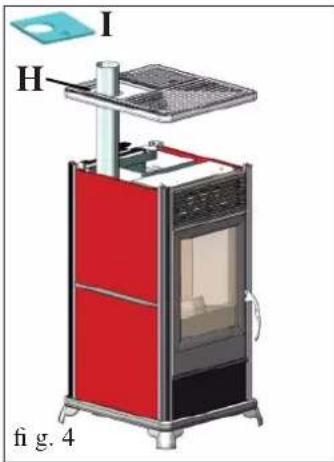
Remove the cast iron top (a - fi g. 2)
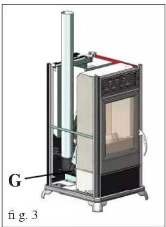
Fit the elbow connection to the smoke extractor unit vent (G - fi g. 3) with the band provided.
AFTER COMPLETING THE CONNECTION OF THE SMOKE OUTPUT PIPE TO THE FLUE, FIT THE CERA-MIC SIDE PANELS AS SHOWN ON THE FOLLOWING PAGE.
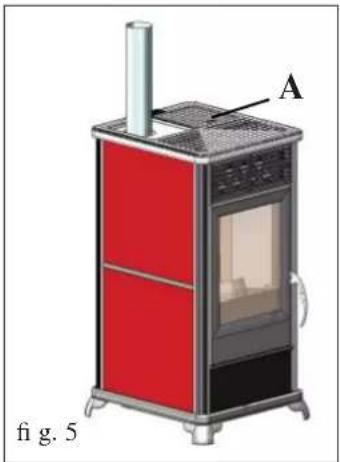
Remove the left cast iron from the top (H-Fig.4) replacing it by the flue cover (I-fig.4) provided, to allow the passage of the pipe.
natural_image
Illustration of a red and black industrial stove with labeled component A, shown in 3D (no text or symbols on the device itself)Before replacing the cast iron top (A - Fig. 5) removed previously, apply the ceramic covering as illustrated on the following page.
ASSEMBLY
natural_image
3D rendering of a portable electric heater with visible internal components and ventilation grille (no text or symbols)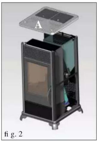
natural_image
Interior view of a portable electronic device with labeled component A, showing internal structure and mounting base (no text or symbols on device)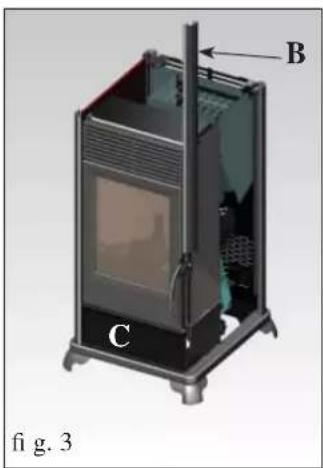
natural_image
3D diagram of a portable air conditioner unit with labeled components (B, C), no text or symbols present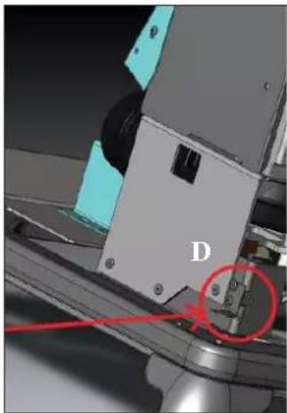
natural_image
Close-up of a mechanical assembly with labeled component 'D' and red circle highlighting a specific part (no readable text or symbols beyond label)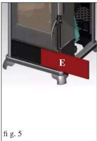
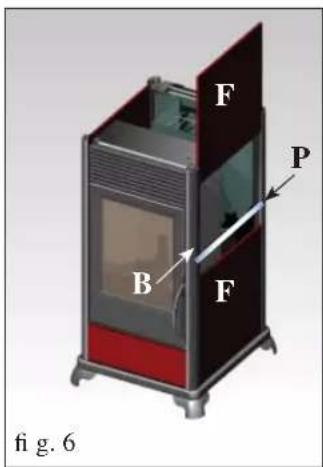
Fig. 1 This illustration shows how the stove will appear once it has been unpacked.
The pieces indicated below are packaged separately.
• 1 ceramic lower front panel (E - Fig. 5)
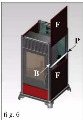
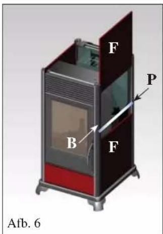
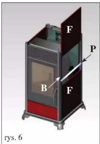
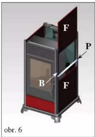
• 4 ceramic side panels (F - Fig. 6)
- 2 aluminium profi les (P - Fig. 6)"
Fig. 2
Unscrew the four fixing screws and remove the cast iron top (A).
Fig. 3
Remove the right-hand front profi le (B) from its housing. Apply the 15x5 gasket to the ceramic front panel support (C).
Fig. 4
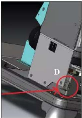
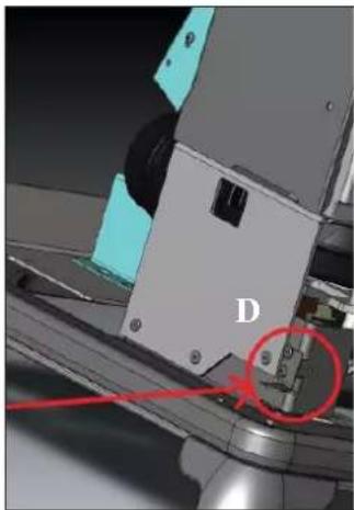
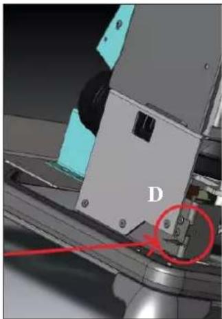
Unscrew one of the two lower centering plates (D).
Fig. 5
"Insert the ceramic lower front panel (E) into its housing.
Reassemble the lower centering plate and right-hand front profile removed previously."
Fig. 6
Insert the ceramic side panels (F) into the relative guides.
Insert an aluminium profi lc (P) between the ceramic side pa-
nels.
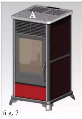
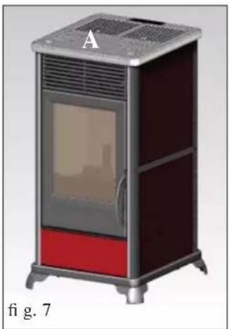
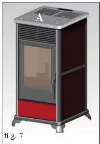
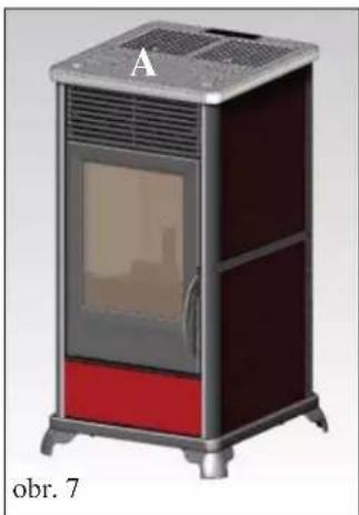
Fig. 7
Replace the cast iron top (A - Fig. 2) removed previously.
N.B.
In the event of vibration, an 8x1 adhesive gasket is provided to place between the profi les and ceramic side panels.
natural_image
Exterior view of a portable electric stove (no signage or text visible)INSTRUCTIONS FOR USE
Commissioning must be done by a Technical Service Centre authorised by Edilkamin (CAT) prior to ignition and testing according to the UNI 10683.
This standard indicates the control operations to be carried out in situ, aimed at ascertaining correct system function.
The CAT will also provide for calibrating the stove on the basis of the type of pellets and the installation conditions, thus allowing for the effectiveness of the guarantee.
Failure to have the stove ignited by an authorised C.A.T. prevents Edilkamin from guaranteeing correct functioning.
for information see the www.edilkamin.com website
There may be a slight smell of paint the first few times it is ignited, however, this will disappear quickly.
Before igniting you must check:
• that installation is correct
• the power supply
• that the door closes properly to a perfect seal
• that the combustion chamber is clean
- that the display is on standby (the date, power or temperature fl ashes).
LOADING THE PELLETS INTO THE HOPPER
Remove the metallic cover in order to fill the hopper* (fi g. 1).
ATTENTION:
use the glove supplied when filling the stove whilst it is running and therefore is hot.
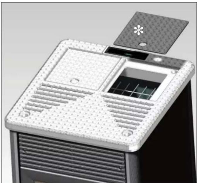
natural_image
3D rendering of a modern air conditioner unit with ventilation grilles and a lid (no text or symbols visible)fig.1
NOTE regarding the fuel.
The stoves is designed and programmed to burn wood pellets with 6 mm diameter.
Pellets are a type of fuel in the form of little cylinders, made from compacted sawdust, compressed under high pressure with no adhesives or foreign materials.
They are sold in bags of 15 kg.
For the stove to function properly, you MUST NOT burn anything else in it. Using other materials (including wood) will render the warranty null and void. Such use is detected by laboratory analyses. Edilkamin has designed, tested and programmed their stoves to guarantee the best performance when pellets with the following characteristics are used:
diameter: 6 millimetres
maximum length: 40 mm
maximum moisture content: 8%
calorifi c value: at least 4300 kcal/kg.
If pellets with different characteristics are used, the stoves must be recalibrated a similar procedure to that carried out by the DEALER when the stove is ignited the first time.
Using unsuitable pellets may: decrease efficiency; cause malfunctions; stop the stove from functioning due to clogging, dirt on the glass, unburnt fuel, etc.
A simple, visual analysis of the pellets may be carried out: Good quality: smooth, uniform length, not very dusty.
Poor quality: with longitudinal and transverse cracks, very dusty, various lengths and mixed with foreign matter.
INSTRUCTIONS FOR USE
SYNOPTIC PANEL


key to set the desired environmental temperature or to enter the menu (set ambient temp.)

key for setting the power of the stove (set power)

on/off or confi rm/quit menu key

indicates that the chrono-thermostat has been programmed for automatic ignition at set times

indicates an alarm condition

indicates the functioning of the pellet-loading motor

this indicates the functioning of the fan

indicates functioning spark plug
MENU DESCRIPTION
• To access the menu press the switches off).

key for 2 seconds (the led
Pressing the key or the key rolls the following menu:
| M1 | Set clock |
| M2 | Set time programme |
| M3 | Adjust vent 1 |
| M4 | (does not appear at display in this model) |
| M5 | Language |
| M6 | Stand-by |
| M7 | Screw loading |
| M8 | Stove status |
| M9 | Technical calibrations (TAC) |
| MA | Type of pellets (TAC) |
| Mb | Quit |
• To confirm the desired menu press the key.
• To go back to the previous menu press the play for 3 seconds.
• To exit the menu press the key for 6 seconds.
SWITCH ON/SWITCH OFF

To switch on/switch off the stove, press the play for 3 seconds.
Led on stove on
Led flashing stove on or in alarm mode
Led off stove off
OPERATING
The stove has two operating modes:
- MANUAL
In MANUAL operating mode, the water temperature at which the stove must operate is set independently from the temperature of the room in which it is installed.
To select MANUAL mode, press the key (the LED will light up).
Pressing the 📂 will increase the temperature until the message ‘MAN’ appears on the display (above 40°).
- AUTOMATIC
In AUTOMATIC mode, it is possible to set the desired temperature of the room where the stove is installed.
When the desired environmental temperature (SET ROOM TEMPERATURE) is reached, the stove will automatically switch to power 1 mode.
To set the desired room temperature, press (The LED turns on) and the current operating temperature will be displayed,
By means of the key or the key is possible to vary the temperature to the desired level.
Ventilation is always correlated to the power in use, so it cannot be varied.
INSTRUCTIONS FOR USE
VENTILATION ADJUSTMENT
This function allows you to manage the ventilation speed.
It can be set to AUTO mode, which automatically adjusts the ventilation speed according to the power of the stove, or you can set the ventilation speed according to the amount of hot air or to the desired noise level of the product.
To activate the function, press the 🔊 key for 2 seconds and press the 🔊 y until the display shows the message “M3 Adjust vent 1”.
Press the 🔊 and set the desired ventilation speed using the keys an 🔒 and 1
To confirm your choice, press the key.
SCREW LOADING (only if the stove is completely without pellets)
To load the screw, enter the MENU by pressing the key 🖱️ for 2 seconds; then press the key 🖱️ until the message “M5 first load” appears on the display.
Press the key 🏠️ to confirm, and then the key 🏠️ to activate the function. This operation must only be carried out when the stove is off and completely cold.
Note: during this phase, the smoke extractor fan will remain on.
STAND-BY FUNCTION
In this mode, the stove will go off when the temperature of the environment is 0.5^ C higher than that requested, after a set time of 10 minutes (which can be changed by the TAC during installation).
The message "GO STBY" will appear on the display, indicating the minutes remaining before switch-off.
This function is available in both 'AUTOMATIC' or 'MANUAL' mode and in the case of an external thermostat.
If the environmental temperature falls to 2^ C below the set threshold, the stove will start up again (setting modifiable by the TAC during installation).
To activate the function, press the key 🖱️ for about 3 seconds; the message “M1 set clock” will appear on the display; press the key 🖱️ until the message “M4 stand by” appears on the display, then confirm by pressing the key 🖱️.
Press the key to select "ON", then confirm by pressing the key.
To quit the menu "M4 stand by", press the key 🤒 about 6 seconds.
SETTING THE DATE AND TIME
Press the key for about 2 second; the message “M1 set clock” will appear on the display; then confirm by pressing the key. The following data will appear in sequence: Day of the week, hour, minutes, day, month, year; these can be changed by pressing
the key or the key. The nfi rm, press the key.
To quit the menu "M1 set clock", press the key ⏻ about 6 seconds.
EXTERNAL THERMOSTAT
This must be connected by the blue wire (optional code 640560) to the serial port positioned on the back of the stove; it must have a clean, normally open contact (e.g. in the case of an environmental thermostat):
- Open contact = Environmental temperature reached
- Closed contact = Environmental temperature not reached
To select ‘E-T’ (external thermostat) mode, press the key 🔒 (the LED will light up). Pressing the key 🔒 will lower the temperature until the message ‘E-T’ (external thermostat) appears on the display (below 6°).
Note: When the stove is off, the external thermostat cannot switch the stove on or off.
If you want to switch the stove on or off outside the set time or outside the 'E-T' (external thermostat) setting, you must always
do so using the key
INSTRUCTIONS FOR USE
CHRONO-THERMOSTAT FOR DAILY/WEEKLY PROGRAMMING
There are 3 types of programming (daily, weekly, weekend), each of which is independent of the others and thus many combinations are possible according to the user's requirements (time programming is in 10 minute steps).
Press the key for 2 seconds; the message "M1 set clock" will appear on the display (and the LED will go out).
Press the key 🖱️ until the message “M2 set chrono” appears on the display; confirm by pressing the key 🖱️.
To visualise the 3 programming modes (daily, weekly, weekend) press the key 🖱 or the key 🕒 and confirm by pressing the key 🕒
Scroll down the following menu (default setting is OFF):
- M2-1: enables the chrono-thermostat
- M2-2: daily programme
- M2-3: weekly programme
- M2-4: weekend programme
- M2-5: Quit
Choose the desired menu and confirm by pressing the key
To set the stove to switch on and off and for time changes press the key 🤗 or the key 🤗, then confirm by pressing the key 🤗. To quit the programme press the key 🤗 about 6 seconds.
Daily programming:
possibility of switching the stove on and off twice throughout the day, repeated every day:
Example: start1 10:00 stop1 12:00 start2 18:00 stop2 22:00
Weekly programming:
possibility of switching the stove on and off 4 times during the day, and to choose the days of the week. For example:
| start1 06:00 stop1 08:00 start2 07:00 stop2 10:00 start3 14:00 stop3 17:00 start4 19:00 stop3 22:00 | |||
| Monday onTuesday onWednesday offThursday onFriday onSaturday offSunday off | Monday offTuesday offWednesday onThursday offFriday offSaturday offSunday off | Monday onTuesday onWednesday offThursday offFriday offSaturday onSunday on | Monday onTuesday onWednesday onThursday onFriday onSaturday onSunday on |
Weekend programming:
possibility of switching the stove on and off twice during the weekend:
Example: start1 week-end 07:00 stop1 week-end 11:30
Example: start2 week-end 14:20 stop2 week-end 23:50
MAINTENANCE
Before performing any maintenance, disconnect the appliance from the mains.
Regular maintenance is required for the stove to function correctly.
IF YOU DO NOT PROVIDE FOR THE NECESSARY MAINTENANCE, the stove will not function correctly.
Any problems resulting from lack of maintenance will immediately void the warranty.
N.B.
- Any unauthorised modification is forbidden
- Use spare parts recommended by the manufacturer
- The use of counterfeit parts results in the guarantee becoming null and void
DAILY MAINTENANCE
Operations must be performed when the stove is off, cold and unplugged from the power supply
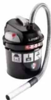
- Cleaning must be carried out with a vacuum cleaner. (optional page 33)
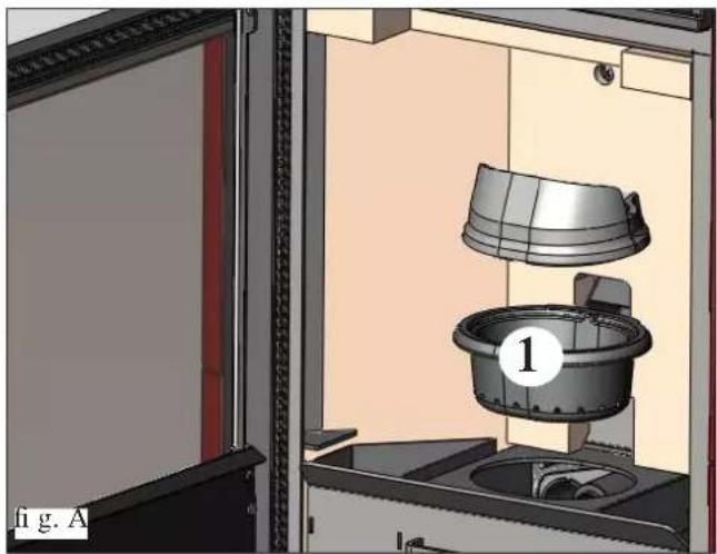
- Open the door, extract the fire box (1 - fig. A) and tip the residue into the ash drawer (2 - fig. B).
- DO NOT EMPTY THE RESIDUE OUT INTO THE PELLET HOPPER.
- Pull the ash drawer (2 - fi g. b) out and empty it into a non-fl ammable container (the ash may still have some parts that are hot and/or embers).
• Vacuum out the inside of the fire box, fire grate, and space around the fire box, into which the ash falls. - Remove the fire box (1 - fig. A) and remove any encrustation using the brush provided, clearing any clogging in the holes.
• Vacuum the fire box, clean the contact edges between the fire box and its seating. - Clean the glass, if necessary (when cold).
Never vacuum hot ash, it can make the vacuum cleaner breakdown and represents a fi re risk.
WEEKLY MAINTENANCE
- Remove the ceiling (3 - fi g. C) and tip the residue into the ash drawer (2 - fi g. B).
The ceiling is a component subject to wear, Edilkamin does not accept responsibility for it, more so if any breaks are due to extracting or putting it back in its seating.
MONTHLY MAINTENANCE
In case of fluc outlet from the top (page 24) clean the internal part of the connecting band removing the inspection (4 - fi g. D)
natural_image
3D rendering of a laboratory apparatus with a bucket and lid, labeled '1' (no text or symbols on the diagram itself)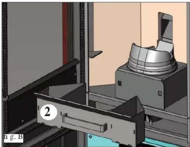
natural_image
3D mechanical assembly diagram showing a clamping device and housing (no text or symbols visible)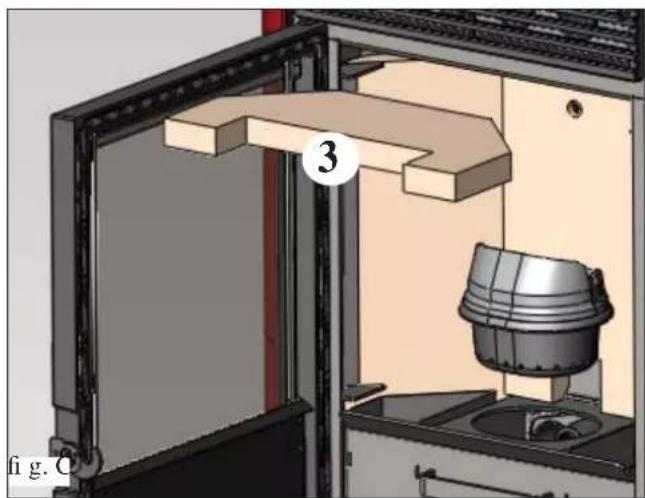
natural_image
3D mechanical assembly diagram showing a door opening, wooden shelf, and a cylindrical component (no text or symbols)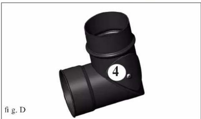
natural_image
3D rendering of a black T-shaped pipe fitting with a numbered label (4) and 'fig. D' at the bottom left (no other text or symbols)MAINTENANCE
(implemented by the DEALER)
Consists of:
- Clean the stove internally and externally
- Thorough cleaning of the heat exchange piping inside the hot air outlet grille located in the upper part of the front of the stove
- Carefully clean and remove dirt from the combustion chamber and the relative compartment
- Clean fans, verify mechanical and clamp loosening
- Clean smoke channel (replace seals on smoke exhaust pipe)
- Clean smoke duct especially if
- Clean/check the Synoptic Panel
- Visual check of power cables, connections and power cord.
- Clean the pellet hopper and check loosening of the feed screw - gear motor assembly
- Check the small pressure-switch pipe, and replace when necessary
- Replace the door seal
- Functionality test: load the feed screw, ignite, let it run for 10 minutes and shutdown
If the stove is used very frequently, it is advisable to clean the smoke channel and the fume duct every 3 months.
ATTENTION !!!
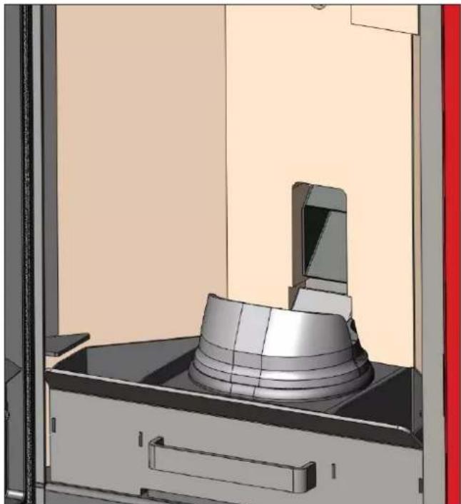
After implementing a normal cleaning procedure, INCORRECT coupling of the upper (A) (fi g. 1) and lower (B) (fi g. 1) combustion chambers can compromise the stove's performance.
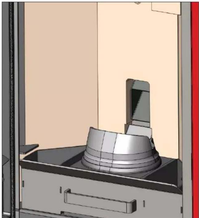
Before igniting the stove, make sure the combustion chambers are correctly paired as indicated in (fig. 2) without ash or unburnt material present on the support perimeter.
We remind you that using the stove without cleaning the melting pot, may cause a sudden ignition gas inside the combustion chamber with the consequent breaking of the glass
N.B.:
The combustion chambers and smoke ducts connected to the solid-fuel appliances must be cleaned once a year (check if your country has specific legislation covering this).
Failure to regularly check and clean increases the likelihood of a fire in the chimney pot.
IMPORTANT!!!
In the case of a fire in the stove, in the flue or in the chimney, proceed as follows:
- Disconnect the power supply
- Use a carbon dioxide (CO₂) extinguisher
- Call the fi re brigade
DO NOT ATTEMPT TO PUT THE FIRE OUT WITH WATER!
After the event, have the appliance checked by an authorised Service Centre and have an authorised technician check the fl ue.
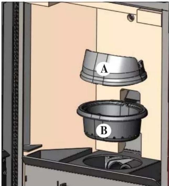
fig.1
natural_image
3D CAD model of a mechanical assembly with a cylindrical component mounted on a base, shown in a view from an open frame (no text or symbols visible)fig.2
ADVICE IN CASE OF PROBLEMS
In the case of problems, the stove will switch off automatically, and an indication of the cause will appear on the display (see the various messages below).
Never pull out the plug when the stove is switching off automatically because of a failure.
In the case of automatic switch-off, the stove must be allowed to complete the entire procedure (15 minutes with an
acoustic signal), after which it can be restarted by pressing the key

However, do not restart the stove until you have found out the cause of the error and until you have CLEANED/EMP-TIED the crucible.
SIGNALS OF POSSIBLE CAUSES OF AN ERROR, TIPS AND SOLUTIONS:
AL1 black out (this is not a stove error) (this takes place if there is no electricity for more than 5 seconds)
The stove has a ‘black out’ function. It the electricity supply is off for less than 5 seconds, the stove will switch on again, returning to the function in progress before it switched off.
If the electricity supply is off for more than 5 seconds, the stove will go into 'black out' alarm, with consequent cooling phase.
The possible causes are listed below:
| Stove status before black-out Interruption of less than 10 seconds | Interruption of more than 10 seconds | |
| OFF OFF OFF | ||
| PRE-LOAD BLACK OUT BLACK OUT | ||
| IGNITION BLACK OUT BLACK OUT | ||
| START-UP START-UP STAND-BY THEN RE-IGNITION | ||
| OPERATING OPERATING STAND-BY THEN RE-IGNITION | ||
| FINAL CLEANING FINAL CLEANING FINAL CLEANING | ||
| STAND-BY | STAND-BY | STAND-BY |
| ALARM | ALARM | ALARM |
| ALARM RECORD | ALARM RECORD | ALARM RECORD |
AL2 broken smoke temp. probe (when the stove can no longer read the smoke temperature)
• Broken thermocouple
• Detached thermocouple
- Smoke temperature out of range
AL3 hot smoke (when the temperature of the smoke exceeds the safety threshold)
- Blocked chimney
- Incorrect installation
- Stove clogged
- Too many pellets loaded, check pellet feed regulation (TAC)
NOTE: the "hot smoke" message appears when the first alarm threshold of 250^ is exceeded, triggering automatic stove regulation; only when the temperature of 270^ is reached does the stove go into alarm mode and switches itself off.
AL4 fan fault (when the motor of the smoke extractor fan breaks down)
- Smoke extraction motor blocked
• Revolution counter breakdown - Smoke motor breakdown
- Smoke motor thermostat triggered
AL5 ignition failure (when the smoke temperature does not reach the minimum threshold during the ignition phase)
• Probable spark plug failure
- Dirty crucible or too many pellets
• The pellets are fi nished
- Check the pellet safety thermostat (automatic reset)
- Blocked chimney
AL6 no pellets (when the pellets are finished)
• There are no more pellets in the hopper
• A gear motor failure
• The screw/pellet duct is blocked
- Too few pellets loaded, check pellet feed regulation
AL7 thermal safety (when the safety thermostat, situated in contact with the hopper, is triggered by the overheating of the pellet hopper)
- Pellet overloading
AL8 no depression (when there is insufficient draught in the cold air aspiration pipe)
- Blocked cold air pipe
- Pressure switch failure
- Blocked silicon pipe
CHECK LIST
To be integrated with a complete reading of the technical specifications
Positioning and installing
• First ignition performed by authorised CAT who released the guarantee certificate
• Air vent in the room
• Only the stove outlet passes through the smoke channel/chimney flue
• Features of the smoke channel (stretch of duct connecting the stove to the flue/chimney):
• a maximum of 3 curves,
a maximum 2 horizontal metres
- Chimney pot that is high enough to avoid downdraft areas
• The discharge pipes are made of a suitable material (stainless steel is recommended)
- When using any flammable materials (e.g. wood), all precautions have been taken to prevent a fire hazard
Use
• Good quality, dry pellets are used
• The chimney pot and ash compartment are clean and well positioned
• The door is closed properly
- The combustion chamber is inserted properly into the relevant compartment
REMEMBER TO VACUUM THE COMBUSTION CHAMBER BEFORE EACH IGNITION Should ignition fail, DO NOT re-ignite until you have emptied the combustion chamber.
OPTIONAL
TELEPHONE DIALLER FOR REMOTE IGNITION
The stove can be ignited remotely by asking the DEALER to connect the telephone combiner to the serial port behind the stove via the optional cable.
• REMOTE CONTROL
CLEANING ACCESSORIES
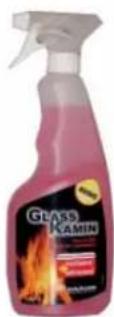
GlassKamin
Used for cleaning the ceramic glass
natural_image
Black industrial vacuum cleaner with attached hose and control panel (no visible text or symbols)Ash vacuum cleaner
User for cleaning the hearth
Madame / Monsieur
natural_image
Exterior view of a modern office building (no signage)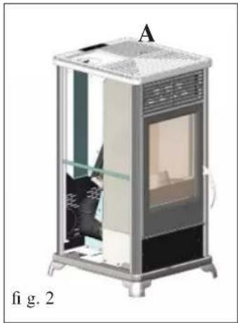
natural_image
Cross-sectional diagram of a mechanical device labeled 'A', showing internal components and no visible text or symbols.SORTIE DES FUMÉES
natural_image
3D diagram of a mechanical device with labeled components (G and fig. 3), no readable text or symbols beyond labels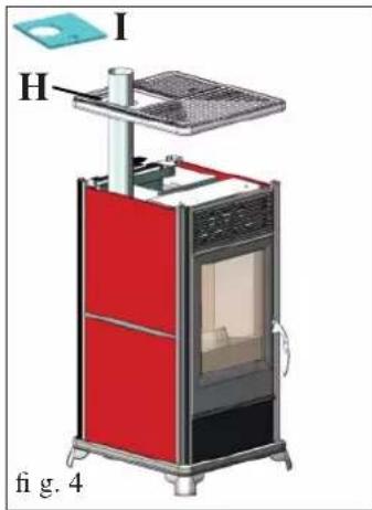
Retirer le haut en fonte (A - fi g. 2)
natural_image
Illustration of a red and black industrial stove with labeled component A, no text or symbols presentnatural_image
Exterior view of a modern office building (no signage)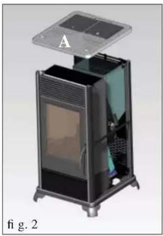
natural_image
3D rendering of a portable electronic device with labeled component A, shown from front and side (no text or symbols on the device itself)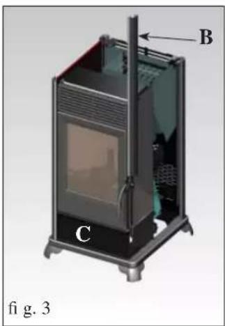
natural_image
3D cutaway diagram of a portable energy storage unit with labeled components (B, C), no text or symbols present.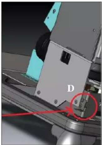
natural_image
Close-up of a mechanical assembly with labeled component D, showing no readable text or symbols beyond the letter 'D'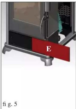
natural_image
Close-up of a mechanical device with red and black components, labeled 'E' (no text or symbols beyond labels)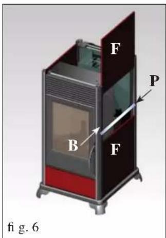
Fig. 1
natural_image
3D rendering of a portable electric stove with red and dark casing, labeled 'A' and 'fig. 7' (no text or symbols on the device itself)MODE D'EMPLOI
natural_image
3D rendering of a white and black industrial air conditioner unit with ventilation grilles and a lid (no text or symbols visible)fig.1

CHRONOTHERMOSTAT A PROGRAMMATION JOURNALIÈRE/HEBDOMADAIRE
natural_image
3D rendering of a mechanical device with a bucket and lid, labeled '1' (no text or symbols on the main diagram)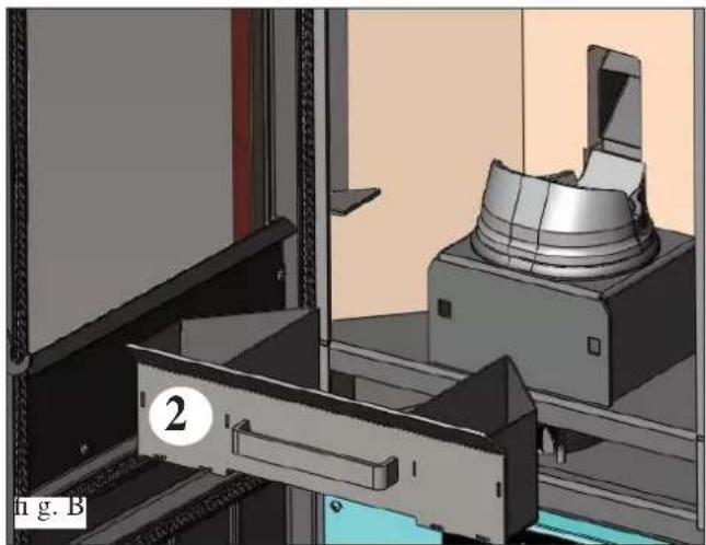
natural_image
3D mechanical assembly diagram showing a clamping device and housing (no text or symbols visible)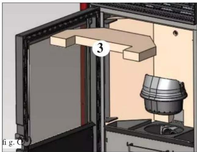
natural_image
3D mechanical assembly diagram showing a door opening, wooden shelf, and a bucket with a numbered component (no text or symbols)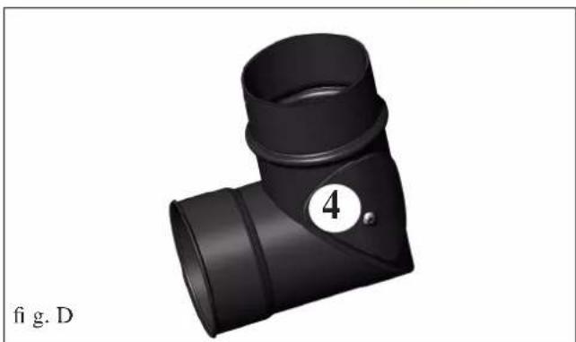
natural_image
3D rendering of a black T-shaped pipe fitting with a numbered circle (4) on the side, labeled 'fig. D' at bottom left (no other text or symbols)ENTRETIEN
ENTRETIEN SAISONNIER
natural_image
3D rendering of a mechanical assembly with a cylindrical component mounted on a base, shown in a view from an open frame (no text or symbols visible)fig.2
CONSEILS EN CAS D'ÉVENTUELS INCONVÉNIENTS
natural_image
Black and white photo of a vacuum cleaner with attached hose and control panel (no visible text or symbols)natural_image
Technical line drawing of a vertical shelf or stand with labeled dimensions (95 and 56), no text or symbols present.PLANTA
natural_image
3D rendering of a modular electronic device with transparent casing and internal compartments (no visible text or symbols)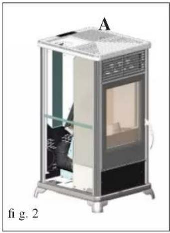
natural_image
Exterior view of a modern office building (no signage)SALIDA DE LOS HUMOS
natural_image
3D diagram of a portable energy storage unit with labeled components (G and fig. 3), no readable text or symbols beyond labels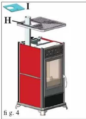
natural_image
3D diagram of a red and black electronic device with labeled components (I, H) and no readable text or symbols beyond labelsnatural_image
Illustration of a red and black industrial stove with labeled component A, shown in 3D style (no text or symbols on the device itself)natural_image
Exterior view of a modern office building (no signage)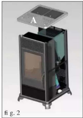
natural_image
3D cutaway view of a device with labeled component A, showing internal structure and mounting base (no text or symbols on the device itself)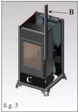
natural_image
3D diagram of a portable stove or oven unit with labeled components (A, B, C), no readable text or symbols beyond labels.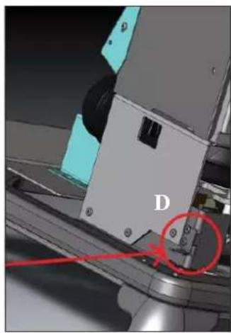
natural_image
Close-up of a mechanical assembly with labeled component 'D' and red circular annotation (no readable text or symbols)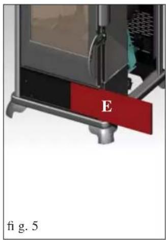
natural_image
Close-up of a mechanical device with labeled component 'E' and part number 'fig. 5' (no readable text or symbols beyond labels)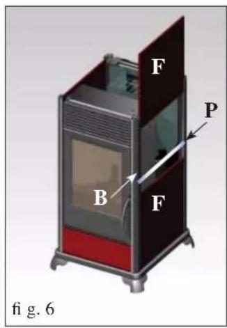
natural_image
3D rendering of a portable electric stove with red and dark casing, labeled 'A' and 'fig. 7' (no text or symbols on the device itself)natural_image
Exterior view of a modern office building (no signage)fig.1

natural_image
3D rendering of a mechanical device with a bucket and lid, labeled '1' (no text or symbols on the main diagram)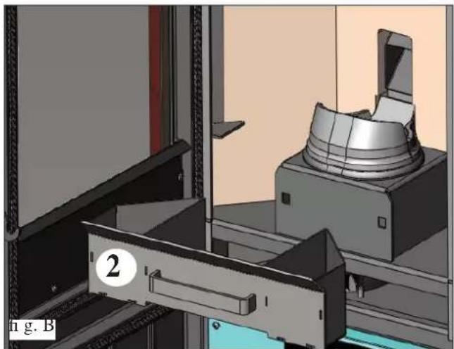
natural_image
3D mechanical assembly diagram showing a rotating component and a bracket with labeled parts (no readable text or symbols)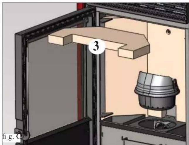
natural_image
3D technical diagram of a mechanical assembly with labeled component (3), showing internal components and no readable text or symbols.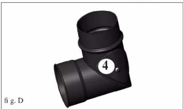
natural_image
3D rendering of a black T-shaped pipe fitting with a numbered circle (4) and label 'fig. D' below (no text or symbols on the object itself)MANTENIMIENTO
natural_image
3D CAD model of a mechanical assembly with a cylindrical component mounted on a base, shown in a view from an open frame (no text or symbols visible)fig.2
CONSEJOS PARA POSIBLES INCONVENIENTES
natural_image
Black and white photo of a vacuum cleaner with attached hose and control panel (no visible text or symbols)Bidón aspira cenizas
natural_image
3D rendering of a modern industrial machine or storage unit with internal compartments and ventilation grilles (no visible text or symbols)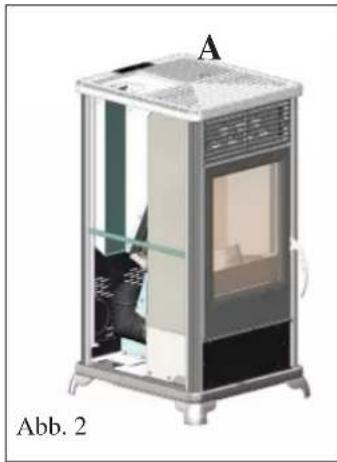
natural_image
3D cutaway illustration of a mechanical device labeled 'A' and 'Abb. 2', showing internal components without any text or symbols beyond labels.RAUCHABZUG
natural_image
Illustration of a red and black industrial stove with labeled component A, no text or symbols presentnatural_image
Exterior view of a modern office building (no signage)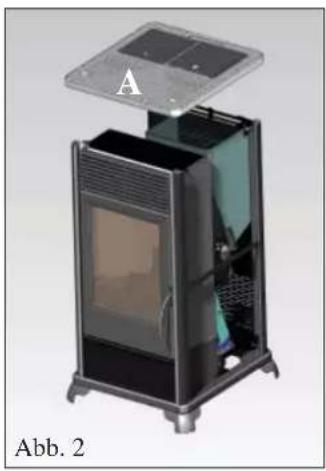
natural_image
Exterior view of a modern office building (no signage)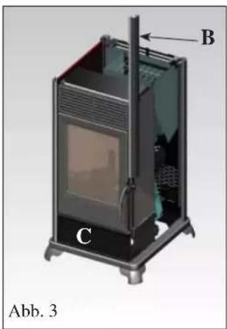
natural_image
Close-up of a mechanical assembly with labeled component D and red circle highlighting a specific area (no readable text or symbols)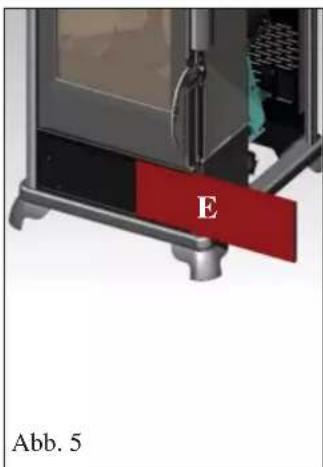

Abb 1
natural_image
Exterior view of a portable electric stove (no signage or text visible)GEBRAUCHSANWEISUNG
natural_image
3D rendering of a white and black industrial air conditioner unit with ventilation grilles and a lid (no text or symbols visible)Abb. 1

natural_image
Interior view of a laboratory apparatus with a bucket labeled '1' and panel label 'Abb. A' (no text or symbols on the diagram itself)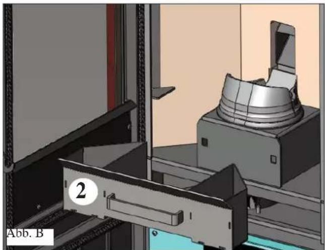
natural_image
3D mechanical assembly diagram showing a component being processed into a housing (no text or symbols visible)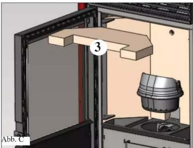
natural_image
3D mechanical assembly diagram showing a door opening, wooden shelf, and a cylindrical component (no text or symbols)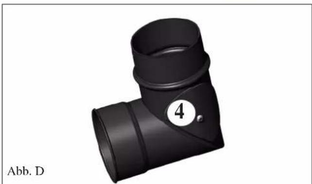
natural_image
Black 3D pipe fitting with a numbered label (4) and Abb. D label, no other text or symbols visible.WARTUNG
natural_image
3D rendering of a mechanical component with a cylindrical housing and mounting bracket (no visible text or symbols)Abb.2
TROUBLE SHOOTING
natural_image
Black and white photo of a vacuum cleaner with attached hose and control panel (no visible text or symbols)natural_image
Illustration of a modern industrial machine with transparent casing and internal compartments (no text or symbols visible)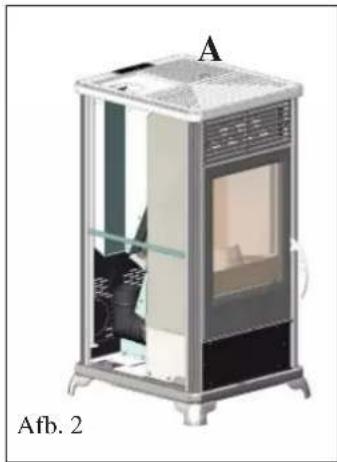
natural_image
Illustration of a mechanical device with labeled components A and Afb. 2, showing internal structure without any text or symbols beyond labels.ROOKGASAFVOER
natural_image
Illustration of a red and black industrial stove with labeled component A, no text or symbols presentnatural_image
Exterior view of a modern electric heating unit with glass doors and ventilation slots (no text or symbols visible)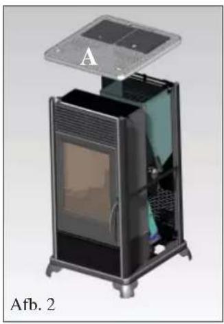
natural_image
Interior view of a modern portable air conditioner unit with labeled component A, showing internal structure and mounting base (no text or symbols on device)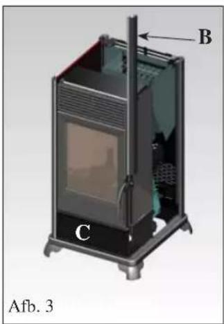
natural_image
3D diagram of a portable air conditioner unit with labeled components A, B, and C (no text or symbols beyond labels)
natural_image
Close-up of a mechanical assembly with labeled component 'D' and red circle highlighting a specific part (no readable text or symbols beyond label)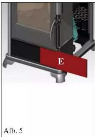
Afb. 1
natural_image
Exterior view of a portable electric stove with red and black casing (no visible text or symbols)GEBRUIKSAANWIJZING
natural_image
Exterior view of a modern office building (no signage)Afb. 1
OPMERKING over de brandstof.

Programmering weekend:
natural_image
3D rendering of a laboratory apparatus with a bucket labeled '1' and panel identifier 'alb. A' (no text or symbols on the diagram itself)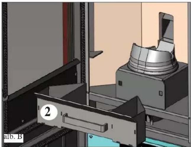
natural_image
3D mechanical assembly diagram showing a component being processed into a machine (no visible text or symbols)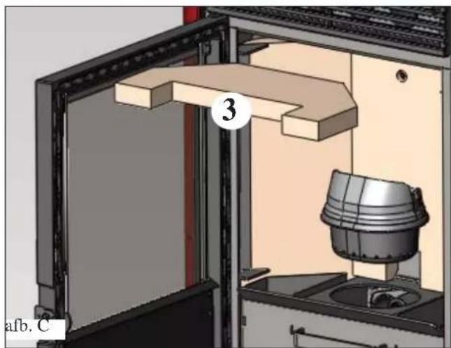
natural_image
3D mechanical assembly diagram showing a door opening, wooden beam, and a cylindrical component (no text or symbols)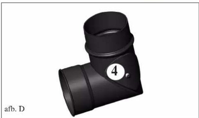
natural_image
3D rendering of a black T-shaped pipe fitting with a numbered circle (4) and label 'afb. D' at the bottom left (no other text or symbols)ONDERHOUD
SEIZOENSGEBONDEN ONDERHOUD
natural_image
3D diagram of a mechanical device with two labeled components (A and B), showing internal structure without any text or symbols.afb.1
natural_image
3D CAD rendering of a mechanical assembly with a cylindrical component mounted on a base, shown in 3D perspective (no text or symbols visible)afb. 2
ADVIES VOOR MOGELIJKE PROBLEMEN
natural_image
Black and white photo of a portable vacuum cleaner with attached hose and control panel (no visible text or symbols)Aszuiger
natural_image
Technical line drawing of a vertical shelf or stand with labeled dimensions (95 and 56), no text or symbols present.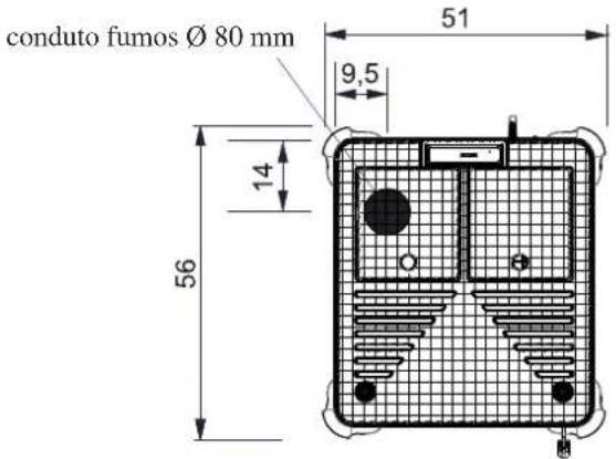
APARELHOS ELETRÓNICOS
PORTA SERIAL
natural_image
3D rendering of a modern industrial machine with transparent casing and internal compartments (no visible text or symbols)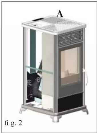
natural_image
Cross-sectional diagram of a mechanical device labeled 'A' and 'fig. 2', showing internal components without any text or symbols beyond labels.SAÍDA DOS FUMOS
natural_image
3D diagram of a portable energy storage unit with labeled components (G and fig. 3), no readable text or symbols beyond labels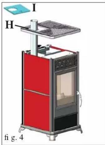
natural_image
3D diagram of a red and black electronic device with labeled components (I, H) and no readable text or symbols beyond labelsRetirar a tampa de ferro gusa (A - dif. 2).
natural_image
Illustration of a red and black industrial stove with labeled component A, shown in 3D style (no text or symbols on the device itself)natural_image
Exterior view of a modern office building (no signage)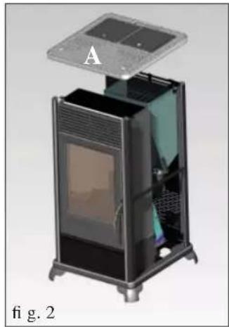
natural_image
3D cutaway view of a device with labeled component A, showing internal structure and mounting base (no text or symbols on the device itself)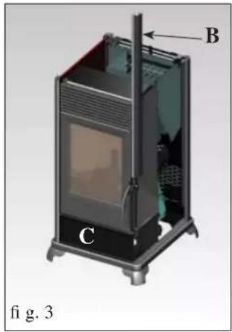
natural_image
3D diagram of a portable stove or oven unit with labeled components (A, B, C), no readable text or symbols beyond labels.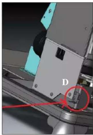
natural_image
Close-up of a mechanical assembly with labeled component 'D' and red circular annotation (no readable text or symbols beyond label)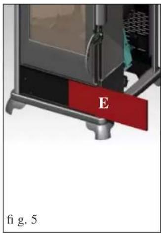
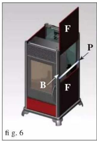
Fig. 1
natural_image
3D rendering of a portable electric stove with red and dark casing, labeled 'A' and 'fig. 7' (no text on device body)INSTRUÇÕES DE USO
natural_image
Exterior view of a modern air conditioner unit with ventilation grilles and a top-mounted lid (no text or symbols visible)fig.1

tecla para programar a temperatura ambiente deseja- da ou para entrar no menu (set temp. ambiente)

natural_image
3D rendering of a mechanical device with a bucket and lid, labeled '1' (no text or symbols on the main diagram)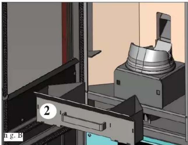
natural_image
3D mechanical assembly diagram showing a clamping device and housing (no text or symbols visible)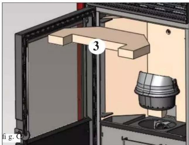
natural_image
3D mechanical assembly diagram showing a door opening, wooden shelf, and a bucket with a numbered label (3) in the center (no readable text or symbols)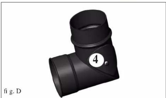
natural_image
3D rendering of a black T-shaped pipe fitting with a numbered label (4) and figure marker (fig. D)MANUTENÇÃO
natural_image
3D rendering of a mechanical assembly with a cylindrical component mounted on a base, shown in a view from an open frame (no text or symbols visible)fig.2
CONSELHOS PARA POSSÍVEIS INCONVENIENTES
natural_image
Black and white photo of a vacuum cleaner with attached hose and control panel (no visible text or symbols)Balde para aspirar
natural_image
Technical line drawing of a vertical shelf or stand with labeled dimensions (95 and 56), no text or symbols present.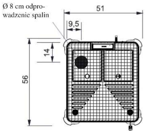
OPIS TECHNICZNY
PORT SZEREGOWY
natural_image
Illustration of a modern cylindrical device with internal compartments and ventilation grilles, labeled 'rys. 1 rys. 2' at the bottom (no other text or symbols)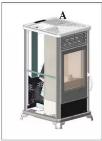
natural_image
Illustration of a modern indoor space shuttle with a person seated inside, labeled 'A' at the top (no text or symbols on the device itself)ODPROWADZENIE SPALIN
natural_image
Illustration of a red and black industrial stove with labeled component A, no text or symbols on the device itselfnatural_image
Exterior view of a modern office building (no signage)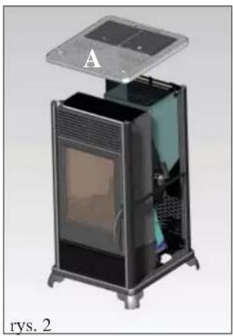
natural_image
Exterior view of a modern office building (no signage)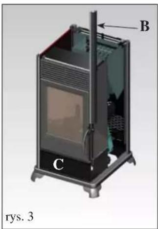
natural_image
Close-up of a mechanical assembly with labeled component D and red circle highlighting a specific part (no readable text or symbols)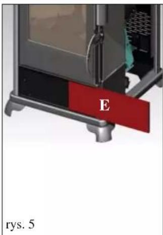
Rys. 1
natural_image
Exterior view of a portable electric stove with red and dark casing (no visible text or symbols)INSTRUKCJA OBSŁUGI
natural_image
3D rendering of a white and black industrial air conditioner unit with ventilation grilles and a lid (no text or symbols visible)rys. 1

M2-2 Programator Dzienny
natural_image
3D rendering of a mechanical device with a bucket and housing, labeled '1' (no text or symbols on the main diagram)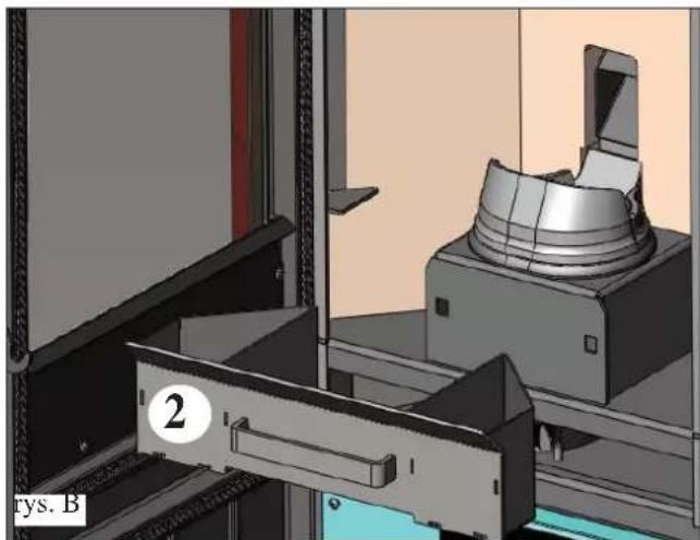
natural_image
3D mechanical assembly diagram showing a component being processed into a housing (no text or symbols visible)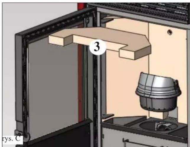
natural_image
3D technical diagram of a mechanical assembly with labeled component (3), no readable text or symbols beyond label and number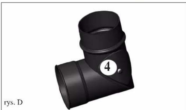
natural_image
Black 3D pipe fitting with a numbered label (4) on the side, no text or symbols on the object itselfKONSERWACJA
KONSERWACJA SEZONOWA
natural_image
3D rendering of a mechanical assembly with a cylindrical component mounted on a base, shown in a view from an open frame (no text or symbols visible)rys. 2
POSTĘPOWANIE W PRZYPADKU NIEPRAWIDŁOWOŚCI
WYPOSAŻENIE DODATKOWE
• KOMBINATOR TELEFONICZNY DO ZDALNEGO ROZPALANIA PIECYKA (kod 762210).
natural_image
Black and white photo of a vacuum cleaner with attached hose and control panel (no visible text or symbols)INFORMACE O BEZPEČNOSTI
natural_image
Technical line drawing of a vertical shelf or stand with labeled dimensions (95 and 56), no text or symbols present.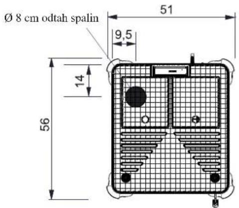
CHARAKTERISTIKY
SÉRIOVÝ PORT
natural_image
3D rendering of a modular industrial machine with transparent casing and internal compartments (no visible text or symbols)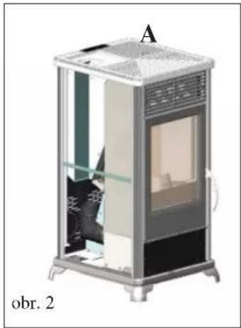
natural_image
Cutaway illustration of a portable electronic device labeled 'obr. 2', showing internal components and ventilation (no text or symbols on the device itself)natural_image
Illustration of a red and black industrial stove with labeled component A, no text or symbols on the device itselfMONTÁŽ OBLOŽENÍ
natural_image
Exterior view of a modern office building (no signage)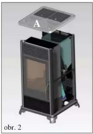
natural_image
Exterior view of a black server or oven unit with open lid and ventilation slots (no visible text or symbols)
natural_image
Close-up of a mechanical assembly with labeled component 'D' and red circle highlighting a specific part (no readable text or symbols beyond label)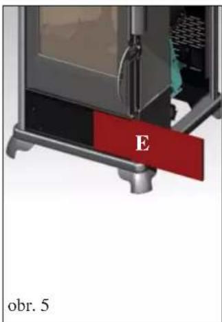
natural_image
Exterior view of a portable electric stove with red and black casing (no visible text or symbols)Obr. 1
natural_image
3D rendering of a modern air conditioner unit with a top panel and ventilation grilles (no text or symbols visible)obr. 1

- M2-3: program týden
- M2-4: program víkend
- M2-5: výstup
natural_image
3D rendering of a mechanical device with a bucket and lid, labeled '1', no visible text or symbols beyond the label.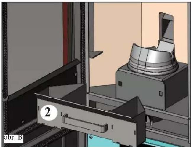
natural_image
3D mechanical assembly diagram showing a clamping device and housing (no text or symbols visible)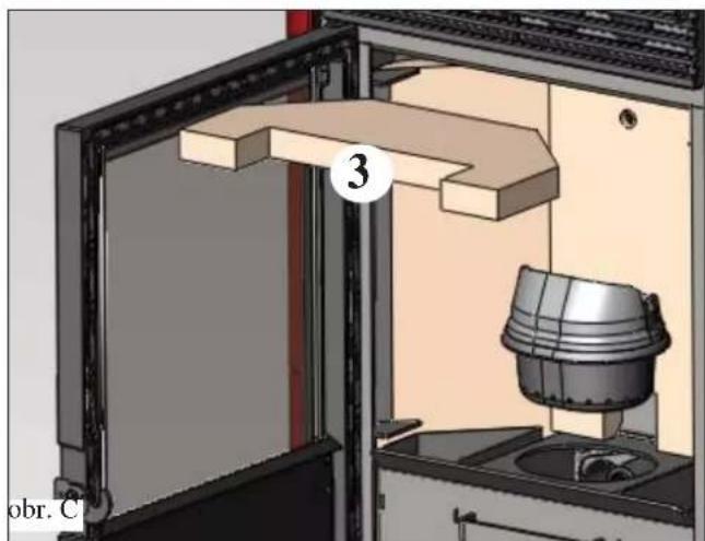
natural_image
3D technical diagram of a mechanical assembly with labeled component (no readable text or symbols)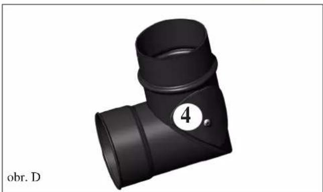
natural_image
3D rendering of a black T-shaped pipe fitting with a numbered circle (4) and label 'obr. D' below (no other text or symbols)ÚDRŽBA
SEZÓNNÍ ÚDRŽBA
natural_image
3D CAD model of a mechanical assembly with a cylindrical component mounted on a base, shown in 3D perspective (no text or symbols visible)obr. 2
PORADCE PŘI MOŽNÝCH POTÍŽÍCH
natural_image
Black and white photo of a vacuum cleaner with attached hose and control panel (no visible text or symbols)Vysavač popela
- CARATTERISTICHE
- PORTA SERIALE
- USCITA FUMI
- MANUTENZIONE
- CONSIGLI PER POSSIBILI INCONVENIENTI
- NOTE
- - Starting up/testing
- - the warranty number necessary for identifying the stove, is indicated:
- SAFETY INFORMATION
- SERIAL PORT
- BACKUP BATTERY
- SAFETY DEVICES
- • THERMOCOUPLE:
- • DIFFERENTIAL PRESSURE SWITCH:
- • SAFETY THERMOSTAT:
- CHARACTERISTICS
- N.B.
- VERIFY COMPATIBILITY WITH OTHER DEVICES
- VERIFYTHE POWER SUPPLY CONNECTION
- (the plug must be accessible)
- FIRE PREVENTION SAFETY DISTANCES
- AIR INTAKE
- SMOKE OUTLET
- CHIMNEY POT
- INSTALLATION
- SMOKE OUTPUT
- ASSEMBLY
- INSTRUCTIONS FOR USE
- LOADING THE PELLETS INTO THE HOPPER
- ATTENTION:
- NOTE regarding the fuel.
- diameter: 6 millimetres
- maximum length: 40 mm
- calorifi c value: at least 4300 kcal/kg.
- SYNOPTIC PANEL
- MENU DESCRIPTION
- SWITCH ON/SWITCH OFF
- OPERATING
- - MANUAL
- - AUTOMATIC
- VENTILATION ADJUSTMENT
- SCREW LOADING (only if the stove is completely without pellets)
- STAND-BY FUNCTION
- SETTING THE DATE AND TIME
- EXTERNAL THERMOSTAT
- CHRONO-THERMOSTAT FOR DAILY/WEEKLY PROGRAMMING
- Daily programming:
- Weekly programming:
- Weekend programming:
- MAINTENANCE
- DAILY MAINTENANCE
- WEEKLY MAINTENANCE
- MONTHLY MAINTENANCE
- (implemented by the DEALER)
- ATTENTION !!!
- IMPORTANT!!!
- ADVICE IN CASE OF PROBLEMS
- SIGNALS OF POSSIBLE CAUSES OF AN ERROR, TIPS AND SOLUTIONS:
- CHECK LIST
- To be integrated with a complete reading of the technical specifications
- Positioning and installing
- Use
- OPTIONAL
- TELEPHONE DIALLER FOR REMOTE IGNITION
- CLEANING ACCESSORIES
- SORTIE DES FUMÉES
- MODE D'EMPLOI
- CHRONOTHERMOSTAT A PROGRAMMATION JOURNALIÈRE/HEBDOMADAIRE
- ENTRETIEN
- ENTRETIEN SAISONNIER
- CONSEILS EN CAS D'ÉVENTUELS INCONVÉNIENTS
- SALIDA DE LOS HUMOS
- MANTENIMIENTO
- CONSEJOS PARA POSIBLES INCONVENIENTES
- RAUCHABZUG
- Abb 1
- GEBRAUCHSANWEISUNG
- WARTUNG
- TROUBLE SHOOTING
- ROOKGASAFVOER
- Afb. 1
- GEBRUIKSAANWIJZING
- OPMERKING over de brandstof.
- Programmering weekend:
- ONDERHOUD
- SEIZOENSGEBONDEN ONDERHOUD
- ADVIES VOOR MOGELIJKE PROBLEMEN
- APARELHOS ELETRÓNICOS
- PORTA SERIAL
- SAÍDA DOS FUMOS
- INSTRUÇÕES DE USO
- MANUTENÇÃO
- CONSELHOS PARA POSSÍVEIS INCONVENIENTES
- OPIS TECHNICZNY
- PORT SZEREGOWY
- ODPROWADZENIE SPALIN
- Rys. 1
- INSTRUKCJA OBSŁUGI
- M2-2 Programator Dzienny
- KONSERWACJA
- KONSERWACJA SEZONOWA
- POSTĘPOWANIE W PRZYPADKU NIEPRAWIDŁOWOŚCI
- WYPOSAŻENIE DODATKOWE
- INFORMACE O BEZPEČNOSTI
- CHARAKTERISTIKY
- SÉRIOVÝ PORT
- MONTÁŽ OBLOŽENÍ
- Obr. 1
- ÚDRŽBA
- SEZÓNNÍ ÚDRŽBA
- PORADCE PŘI MOŽNÝCH POTÍŽÍCH
Brand : EDILKAMIN
Model : CLASSICA
Category : Wood stove