
BCM 191 - Air Conditioning Master - Free user manual and instructions
Find the device manual for free BCM 191 Master in PDF.

| Product type | Air cooler (adiabatic cooling) |
| Brand | Master |
| Model | BCM 191 |
| Use | Cool, humidify, ventilate or remove dust |
| Installation location | Outdoor only (roof or wall) |
| Power supply | Voltage and frequency according to nameplate; grounding mandatory |
| Minimum distance to walls | 0.5 m |
| Maximum water pressure | 3 Bar |
| Recommended ambient temperature | 18 °C to 45 °C |
| Maximum water temperature | 45 °C |
| Air speed in duct | 3 to 6 m/s |
| Recommended duct material | Galvanized sheet, plastic or fiberglass |
| Network configuration | Up to 31 machines, 4 zones, individual or zone modes |
| Available functions | Cooling, ventilation, extraction, cleaning |
| Scheduling | Auto or manual |
| Control | Screen with temperature/humidity probe |
| Maintenance of tank | Periodic draining and sanitization according to use |
| Maintenance of panels | Periodic inspection and sanitization of cooling pads |
| Recommended biocide product | Compliant with EU Regulation No. 582/2012 |
| UV lamp | Annual check and cleaning by after-sales service |
Frequently Asked Questions - BCM 191 Master
User questions about BCM 191 Master
0 question about this device. Answer the ones you know or ask your own.
Ask a new question about this device
Download the instructions for your Air Conditioning in PDF format for free! Find your manual BCM 191 - Master and take your electronic device back in hand. On this page are published all the documents necessary for the use of your device. BCM 191 by Master.
USER MANUAL BCM 191 Master
natural_image
Icon of an open book with an exclamation mark inside a diamond shape, set against a yellow and gray background (no text or symbols)USER AND MAINTENANCE MANUAL
BCM 191AB - BCM 191AL - BCM 191AU
BCM 311AB - BCM 311AU
BCM 511AB - BCM 511AU
| en | it | de | es | fr | nl | pt | da | pl | ru | cs | hu | tr | lt |
| lv | et | ro | sk | bg | el |
NOTE:
TECHNICAL DATA - DATI TECNICI - TECHNISCHE DATEN - DATOS TÉCNICOS - DONNÉES TECHNIQUES - TECHNISCHE GEGEVENS - DADOS TÉCNICOS - TEKNISKE DATA - TEKNISET TIEDOT - TEKNISKE DATA - TEKNISKA DATA - DANE TECHNICZNE - ТЕХНИЧЕСКИЕ ДАННЫЕ - TECHNICKÉ ÚDAJE - MŰSZAKI ADATOK - TEHNIČNI PODATKI - TEKNÍK VERİLER - TEHNIČKI PODACI - TECHNINIAI DUOMENYS - TEHNISKIE DATI - TEHNILISED ANDMED - DATE TEHNICE - TECHNICKÉ ÚDAJE - ТЕХНИЧЕСКИ ДАННИ - ТЕХНІЧНІ ДАНІ - TEHNIČKI PODACI - ТЕХNIKA ĐЕДОМENA - 技术参数 - ТЕХНИКАЛЫК КОРСЕТКІШТЕР
| MODEL | BCM 191... BCM 311... BCM 511... | |
 | 19.000 m^3/h-m^3/ч 31.000 m^3/h-м^3/ч 50.000 m^3/h-м^3/ч | |
 | 180 Pa-Па 260 Pa-Па 460 Pa-Па | |
 | 220-240 V-B50 Hz-Гц1,1 kW-кВт | 3N~380-400 V-B50-60 Hz-Гц3 kW-кВт |
 | 55 kg-кг 86 kg-кг | 112 kg-кг |
| IP55 IP55 IP55 |
TECHNICAL DATA - DATI TECNICI - TECHNISCHE DATEN - DATOS TÉCNICOS - DONNÉES TECHNIQUES - TECHNISCHE GEGEVENS - DADOS TÉCNICOS - TEKNISKE DATA - TEKNISET TIEDOT - TEKNISKE DATA - TEKNISKA DATA - DANE TECHNICZNE - ТЕХНИЧЕСКИЕ ДАННЫЕ - TECHNICKÉ ÚDAJE - MŰSZAKI ADATOK - TEHNIČNI PODATKI - TEKNÍK VERÍLER - TEHNIČKI PODACI - TECHNINIAI DUOMENYS - TEHNISKIE DATI - TEHNILISED ANDMED - DATE TEHNICE - TECHNICKÉ ÚDAJE - ТЕХНИЧЕСКИ ДАННИ - ТЕХНІЧНІ ДАНІ - TEHNIČKI PODACI - ТЕХNIKA ДЕДОМENA - 技术参数 - ТЕХНИКАЛЬІК КОРСЕТКІШТЕР
| CABLE SPECIFICATION | ||
| FEATURES: DESCRIPTION: STANDARD: | ||
| Type (N° x mm2): 2 x 0,50 | ||
| ∅ Medium outer (mm): 5,4 | ||
| Conductors: Annealed red copper cl. 5 CEI EN 60228 | ||
| Insulation: PVC, quality R2 CEI EN 50363 | ||
| Shield: Al/Pet tape | ||
| Shield: Braid of annealed red copper | ||
| Sheath: PVC, quality Rz CEI EN 50363 | ||
| Fire retardant: CEI 20-22/II | ||
| Flame retardant: CEI EN 60332-1-2 | ||
| Low halogens emission: (< 22 %) | CEI EN 50267-2 | -1 - IEC 60754-1 |
| UV resistant: | HD 605 | |
| DC resistance: | Max resistance of conductor at 20 °C:NAKED WIRE 39 Ω/KmINSULATED WIRE 40,1 Ω/Km | CEI EN 60228 |
| Testing voltage: | 2000 V | |
| Max working temperature: | 70 °C | |
| Short-circuit temperature: | 160 °C | |
| Min. installation temperature: | 0 °C | |
| Bending radius: | ∅ x 8 | |
| Max standard twisting (cable 2x): | ≥ 10 twists/meter | |
PICTURES - FIGURE - ABBILDUNGEN - FIGURAS - FIGURES - FIGUREN - FIGURAS - FIGURER - KUVAT - FIGURER - FIGURER - ILUSTRACJE - ИЛЛЮСТРАЦИИ - OBRÁZKY - ÁBRÁK - SLIKE - ŞEKİLLER - SLIKE - ILIUSTRACIJOS - ATTĚLI - JOONISED - IMAGINI - OBRÁZKY - CXEMI - ДАHI - EIKONEΣ - 图示 - СУРЕТТЕМЕЛЕР
natural_image
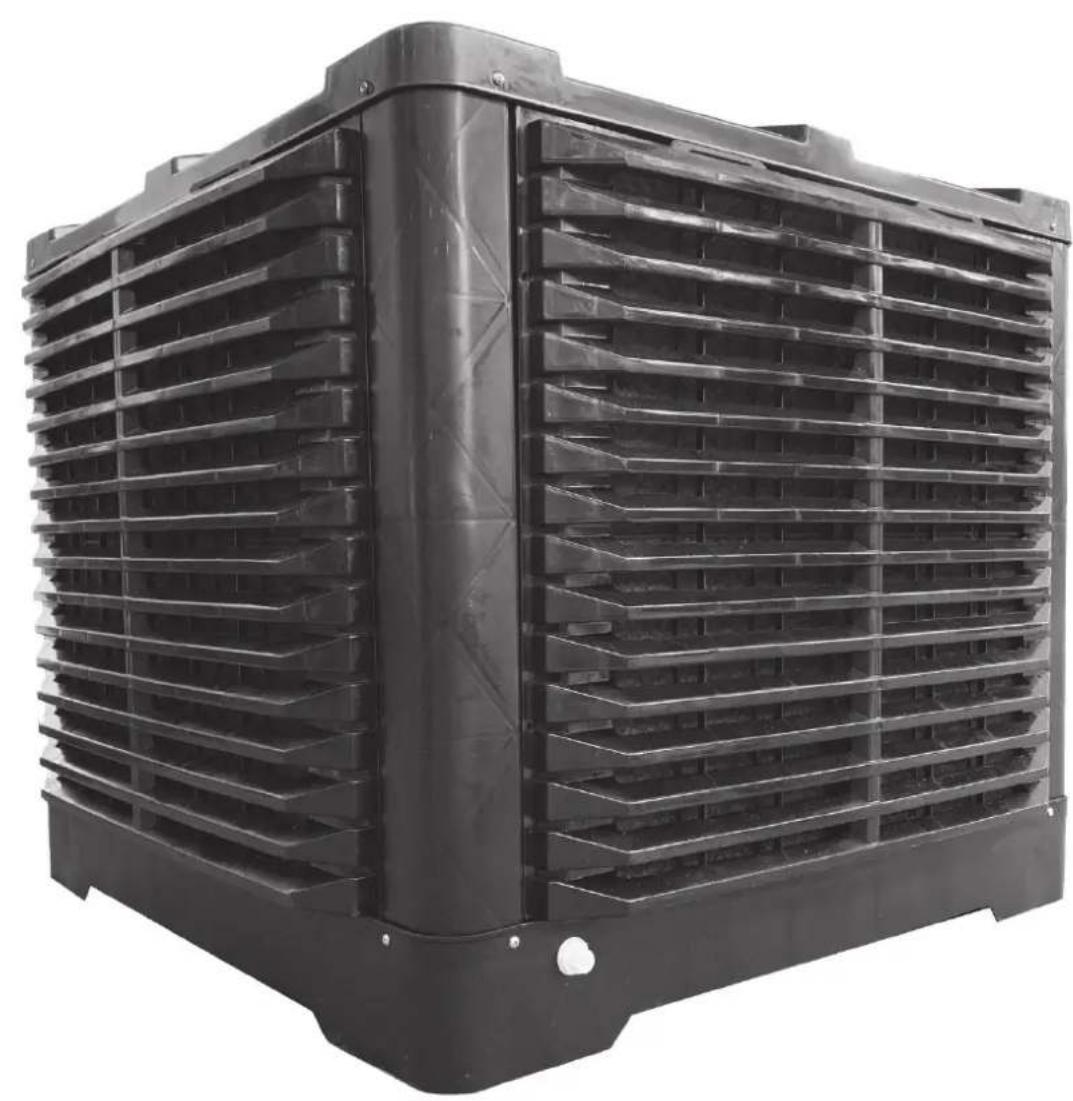
Black plastic industrial fan or vent with horizontal slats and a side panel, no visible text or symbolsPICTURES - FIGURE - ABBILDUNGEN - FIGURAS - FIGURES - FIGUREN - FIGURAS - FIGURER - KUVAT - FIGURER - FIGURER - ILUSTRACJE - ИЛЛЮСТРАЦИИ - OBRÁZKY - ÁBRÁK - SLIKE - ŞEKİLLER - SLIKE - ILIUSTRACIJOS - ATTĚLI - JOONISED - IMAGINI - OBRÁZKY - CXEMI - ДАНИ - EIKONEΣ - 图示 - СУРЕТТЕМЕЛЕР
natural_image
Worker assembling a large storage unit in a warehouse, with arrows indicating process flow (no text or symbols)PICTURES - FIGURE - ABBILDUNGEN - FIGURAS - FIGURES - FIGUREN - FIGURAS - FIGURER - KUVAT - FIGURER - FIGURER - ILUSTRACJE - ИЛЛЮСТРАЦИИ - OBRÁZKY - ÁBRÁK - SLIKE - ŞEKİLLER - SLIKE - ILIUSTRACIJOS - ATTĚLI - JOONISED - IMAGINI - OBRÁZKY - CXEMI - ДАHI - EIKONEΣ - 图示 - СУРЕТТЕМЕЛЕР

PICTURES - FIGURE - ABBILDUNGEN - FIGURAS - FIGURES - FIGUREN - FIGURAS - FIGURER - KUVAT - FIGURER - FIGURER - ILUSTRACJE - ИЛЛЮСТРАЦИИ - OBRÁZKY - ÁBRÁK - SLIKE - ŞEKİLLER - SLIKE - ILIUSTRACIJOS - ATTĚLI - JOONISED - IMAGINI - OBRÁZKY - CXEMI - ДАНИ - EIKONEΣ - 图示 - СУРЕТТЕМЕЛЕР
PICTURES - FIGURE - ABBILDUNGEN - FIGURAS - FIGURES - FIGUREN - FIGURAS - FIGURER - KUVAT - FIGURER - FIGURER - ILUSTRACJE - ИЛЛЮСТРАЦИИ - OBRÁZKY - ÁBRÁK - SLIKE - ŞEKİLLER - SLIKE - ILIUSTRACIJOS - ATTĚLI - JOONISED - IMAGINI - OBRÁZKY - CXEMI - ДАHI - EIKONEΣ - 图示 - СУРЕТТЕМЕЛЕР
natural_image
Close-up of a hand holding a black cable with a white connector, attached to a mechanical component (no visible text or symbols)PICTURES - FIGURE - ABBILDUNGEN - FIGURAS - FIGURES - FIGUREN - FIGURAS - FIGURER - KUVAT - FIGURER - FIGURER - ILUSTRACJE - ИЛЛЮСТРАЦИИ - OBRÁZKY - ÁBRÁK - SLIKE - ŞEKİLLER - SLIKE - ILIUSTRACIJOS - ATTĚLI - JOONISED - IMAGINI - OBRÁZKY - CXEMI - ДАHI - EIKONEΣ - 图示 - СУРЕТТЕМЕЛЕР
natural_image
Close-up of a hand holding a white cable or wire attached to a car interior, with no visible text or symbols.PICTURES - FIGURE - ABBILDUNGEN - FIGURAS - FIGURES - FIGUREN
- FIGURAS - FIGURER - KUVAT - FIGURER - FIGURER - ILUSTRACJE
- ИЛЛЮСТРАЦИИ - ОВРАЗКУ - АВРАК - SLIKE - ŞEKİLLER - SLIKE -
ILIUSTRACIJOS - ATTÉLI - JOONISED - IMAGINI - OBRÁZKY - CXEMI - ДАHI
- EIKONEΣ - 图示 - СУРЕТТЕМЕЛЕР
BCM 191...
flowchart
graph TD
    M["Motor"] --> J11["J11"]
    M --> J15["J15"]
    J11 --> J22["J22"]
    J15 --> J22
    J22 --> UV["LAMP"]
    J22 --> PowerSupply["Power Supply"]
    J22 --> PumpDRAIN["Pump Drain"]
    J22 --> SOLENOIDVALVE["SOLENOID VALVE"]
    J22 --> INFAILLL["N"]
    J22 --> AUXSWING["L"]
    J22 --> PUMP["L"]
    J22 --> DRAIN["L"]
    J22 --> 230Vac["230 Vac / 50 Hz"]
    J22 --> WATERLEVELSENSOR["WATER LEVEL SENSOR"]
    J22 --> NTCSENSOR["NTC SENSOR"]
PICTURES - FIGURE - ABBILDUNGEN - FIGURAS - FIGURES - FIGUREN - FIGURAS - FIGURER - KUVAT - FIGURER - FIGURER - ILUSTRACJE - ИЛЛЮСТРАЦИИ - OBRÁZKY - ÁBRÁK - SLIKE - ŞEKİLLER - SLIKE - ILIUSTRACIJOS - ATTĚLI - JOONISED - IMAGINI - OBRÁZKY - CXEMI - ДАНИ - EIKONEΣ - 图示 - СУРЕТТЕМЕЛЕР
flowchart
graph TD
    A["BCM 191... - DISPLAY 1"] --> B["DISPLAY"]
    B --> C["J11"]
    B --> D["J15"]
    C --> E["Control Interface"]
    D --> E
    style A fill:#f9f,stroke:#333
    style B fill:#ccf,stroke:#333
    style C fill:#cfc,stroke:#333
    style D fill:#fcc,stroke:#333
flowchart
graph TD
    A["BCM 191... - DISPLAY 2"] --> B["DISPLAY"]
    B --> C["J11"]
    B --> D["J15"]
    C --> E["Device Interface"]
    D --> E
    E --> F["J11"]
    E --> G["J15"]
PICTURES - FIGURE - ABBILDUNGEN - FIGURAS - FIGURES - FIGUREN
- FIGURAS - FIGURER - KUVAT - FIGURER - FIGURER - ILUSTRACJE
- ИЛЛЮСТРАЦИИ - ОВРАЗКУ - АВРАК - SLIKE - ŞEKİLLER - SLIKE -
ILIUSTRACIJOS - ATTËLI - JOONISED - IMAGINI - OBRÁZKY - CXEMI - ДАHI
- EIKONEΣ - 图示 - СУРЕТТЕМЕЛЕР
BCM 311-511...
flowchart
graph TD
    A["380 Vac / 50 Hz"] --> B["NTC SENSOR"]
    B --> C["POWER SUPPLY 380Vac"]
    C --> D["MOTOR"]
    D --> E["POWER SUPPLY 230Vac"]
    E --> F["AUX SWING"]
    F --> G["VALVE +12Vdc"]
    F --> H["PUMP L N"]
    F --> I["DRAIN L N"]
    F --> J["SOLENOID VALVE"]
    C --> K["POWER SUPPLY 380Vac"]
    K --> L["VALVE +12Vdc"]
    K --> M["PUMP L N"]
    K --> N["DRAIN L N"]
    K --> O["SOLENOID VALVE"]
    style A fill:#f9f,stroke:#333
    style B fill:#ccf,stroke:#333
    style C fill:#cfc,stroke:#333
    style D fill:#fcc,stroke:#333
    style E fill:#cff,stroke:#333
    style F fill:#ffc,stroke:#333
    style G fill:#fcc,stroke:#333
    style H fill:#ffc,stroke:#333
    style I fill:#fcc,stroke:#333
    style J fill:#fcc,stroke:#333
    style K fill:#cff,stroke:#333
    style L fill:#fcc,stroke:#333
    style M fill:#fcc,stroke:#333
    style N fill:#fcc,stroke:#333
    style O fill:#fcc,stroke:#333
    subgraph J16
        P["COM S-L S-H GND SIG *5V NTC NTC"]
        Q["NTC SENSOR"]
        R["WATER LEVEL SENSOR"]
    end
    subgraph J4 J5
        S["GND TDB-TDB-"]
        T["SERIAL RS485"]
        U["12V"]
        V["UV LAMP"]
        W["PUMP"]
        X["DRAIN"]
    end
PICTURES - FIGURE - ABBILDUNGEN - FIGURAS - FIGURES - FIGUREN - FIGURAS - FIGURER - KUVAT - FIGURER - FIGURER - ILUSTRACJE - ИЛЛЮСТРАЦИИ - OBRÁZKY - ÁBRÁK - SLIKE - ŞEKİLLER - SLIKE - ILIUSTRACIJOS - ATTĚLI - JOONISED - IMAGINI - OBRÁZKY - CXEMI - ДАНИ - EIKONEΣ - 图示 - СУРЕТТЕМЕЛЕР
flowchart
graph TD
    A["BCM 311-511... - DISPLAY 1"] --> B["DISPLAY"]
    B --> C["J4 J5"]
    C --> D["Display 2"]
    D --> E["BCM 311-511... - DISPLAY 2"]
PICTURES - FIGURE - ABBILDUNGEN - FIGURAS - FIGURES - FIGUREN - FIGURAS - FIGURER - KUVAT - FIGURER - FIGURER - ILUSTRACJE - ИЛЛЮСТРАЦИИ - OBRÁZKY - ÁBRÁK - SLIKE - ŞEKİLLER - SLIKE - ILIUSTRACIJOS - ATTĚLI - JOONISED - IMAGINI - OBRÁZKY - CXEMI - ДАHI - EIKONEΣ - 图示 - СУРЕТТЕМЕЛЕР
natural_image
Close-up of hands installing a white electrical outlet component with a magnified inset showing the plug being inserted (no text or symbols visible)PICTURES - FIGURE - ABBILDUNGEN - FIGURAS - FIGURES - FIGUREN - FIGURAS - FIGURER - KUVAT - FIGURER - FIGURER - ILUSTRACJE - ИЛЛЮСТРАЦИИ - OBRÁZKY - ÁBRÁK - SLIKE - ŞEKİLLER - SLIKE - ILIUSTRACIJOS - ATTĚLI - JOONISED - IMAGINI - OBRÁZKY - CXEMI - ДАHI - EIKONEΣ - 图示 - СУРЕТТЕМЕЛЕР
natural_image
Close-up of hands installing or adjusting a white plastic component on a kitchen fixture (no visible text or symbols)PICTURES - FIGURE - ABBILDUNGEN - FIGURAS - FIGURES - FIGUREN - FIGURAS - FIGURER - KUVAT - FIGURER - FIGURER - ILUSTRACJE - ИЛЛЮСТРАЦИИ - OBRÁZKY - ÁBRÁK - SLIKE - ŞEKİLLER - SLIKE - ILIUSTRACIJOS - ATTĚLI - JOONISED - IMAGINI - OBRÁZKY - CXEMI - ДАHI - EIKONEΣ - 图示 - СУРЕТТЕМЕЛЕР
PICTURES - FIGURE - ABBILDUNGEN - FIGURAS - FIGURES - FIGUREN - FIGURAS - FIGURER - KUVAT - FIGURER - FIGURER - ILUSTRACJE - ИЛЛЮСТРАЦИИ - OBRÁZKY - ÁBRÁK - SLIKE - ŞEKİLLER - SLIKE - ILIUSTRACIJOS - ATTĚLI - JOONISED - IMAGINI - OBRÁZKY - CXEMI - ДАНИ - EIKONEΣ - 图示 - СУРЕТТЕМЕЛЕР
natural_image
Exterior view of a modern office building (no signage)PARAGRAPH SUMMARY PARAGRAPH SUMMARY
| 1... SAFETY INFORMATION |
| 2... UNPACKING |
| 3... ASSEMBLY AND INSTALLATION(ONLY FOR QUALIFIED PERSONNEL) |
| 4... OPERATION |
| 5... CLEANING AND MAINTENANCE |
| 6... TROUBLESHOOTING |
IMPORTANT: READ AND UNDERSTAND THIS OPERATIONAL MANUAL PRIOR TO ASSEMBLING, STARTING UP OR CONDUCTING MAINTENANCE ON THIS COOLER. USING THE COOLER INCORRECTLY CAN CAUSE SERIOUS OR FATAL INJURIES. KEEP THIS MANUAL FOR FURTHER REFERENCE.
▶▶▶1. INFORMATION ON SAFETY
(Pic. 1)
IMPORTANT: This appliance is not suitable for use by persons (including children) with reduced physical, sensory and mental capacities or with lack of experience or knowledge unless supervised by a person responsible for their safety. Children must be supervised to make sure they do not play with the appliance.
▶1.1. During installation, the electrical connection, water connection, use and maintenance of the cooler, comply with all local regulations and standards in force.
▶1.2. The cooler must only be installed, adjusted and serviced by qualified personnel.
▶1.3. Use this appliance to cool, dehumidify, ventilate or remove dust.
▶1.4. In order to prevent the risk of fire or serious injuries, install the cooler at a safe distance from heat sources (fireplaces, fire, etc.), from sparks (welding machines, electrical panels, etc.) or from combustion fumes (hoods, chimney flues, etc.).
▶1.5. Improper wiring or improper installation can cause hazards or serious damage.
▶1.6. Before carrying out any operation, make sure that the cooler, the power supply cable, the control panel, etc., are perfectly dry, in order to prevent any hazard or serious damage (never work with wet hands).
▶1.7. Only install outdoors.
▶1.8. The cooler must be installed on a stable and level structure, so as to prevent any risk (the structure and the plugs must be adequate to support the weight of the appliance).
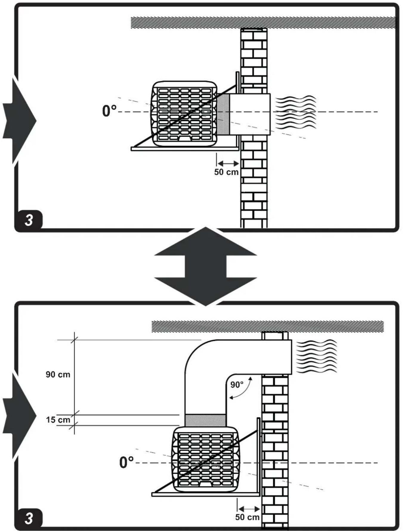
▶1.9. The minimum safety distance recommended between the cooler and walls or other items is 0.5 m.
▶1.10. A 0.8 m ^2 outlet for every 3,600 m ^3 /h of air supplied to the cooler must be provided (always ensure an exchange of air within the cooled environment). In the event of forced air ventilation, the amount extracted should be less than 85% of the air intake. Forced ventilation can be combined with natural ventilation.
▶1.11. Power the cooler solely with the voltage and frequency specified on the nameplate, using cables of suitable section (the supply voltage must not vary more than ± 5% from the value stated on the nameplate).
▶1.12. Make sure the cooler is earthed properly.
▶1.13. Make sure the polarities are respected when connecting to the mains. We recommend using a suitable residual current device (see nameplate).
▶1.14. The cooler can withstand a maximum water inlet pressure of 3 Bar. If the pressure of the water supply is higher, a pressure reducer must be installed.
▶1.15. Only fill the cooler tank only with clean water.
▶1.16. We recommend using horizontal coverage to protect from weathering, in order to preserve the cooler over time.
▶1.17. It is forbidden to alter, tamper with or adjust the cooler and the electricity or water supply after installation, if it is not carried out by qualified personnel.
▶1.18. Do not obstruct, even partially, the air vents of the cooler, in order to prevent a hazard.
▶1.19. In order to prevent serious damage, do not let dust, dirt or other materials come into contact with the cooler.
▶1.20. We recommend using the cooler with ambient temperatures between 18^ C and 45^ C and with water temperature below 45^ C.
▶1.21. In order to prevent serious breakdowns, when the temperatures drop to about <2^ , completely empty the tank and the pipes that supply water to the cooler.
▶1.22. Disconnect the power supply when you handle or service the cooler (use personal protective equipment in order to prevent any hazards).
▶1.23. If the power supply cable is damaged, it must be replaced by a technical support centre to prevent any risk.
▶1.24. Protect the power cable from potential damage caused by the movement of vehicles, pedestrians, weathering and heat sources.
▶1.25. If the cooler malfunctions, contact the technical support centre.
▶1.26. Unplug the cooler from the power supply, when it is not used for a medium to long term period.
▶1.27. The water used to fill the cooler tank must come from an aqueduct. If it is not possible to draw from an aqueduct, the water introduced must be subjected to a sanitation treatment, according to European Directive 98/83/EC.
-We recommend using water with a hardness of less than 15^ f.
-The cooler tank must be emptied and sanitised periodically depending on the use.
-The cooling pad surfaces must be periodically inspected and sanitised depending on the use.
-For sanitation operations, biocidal products that comply with European regulation no. 582/2012 must be used.
▶▶▶2. UNPACKING
IMPORTANT: IT IS STRICTLY FORBIDDEN TO STACK TWO OR MORE COOLERS.
▶2.1. Remove all packaging material used to pack and deliver the cooler and dispose of it in compliance with current standards.
▶2.2. Remove all items from the packaging.
▶2.3. Check for any damage incurred during transport. If the cooler appears damaged, immediately inform the dealer from whom it was purchased.
▶▶▶3. ASSEMBLY AND INSTALLATION (ONLY FOR QUALIFIED PERSONNEL)
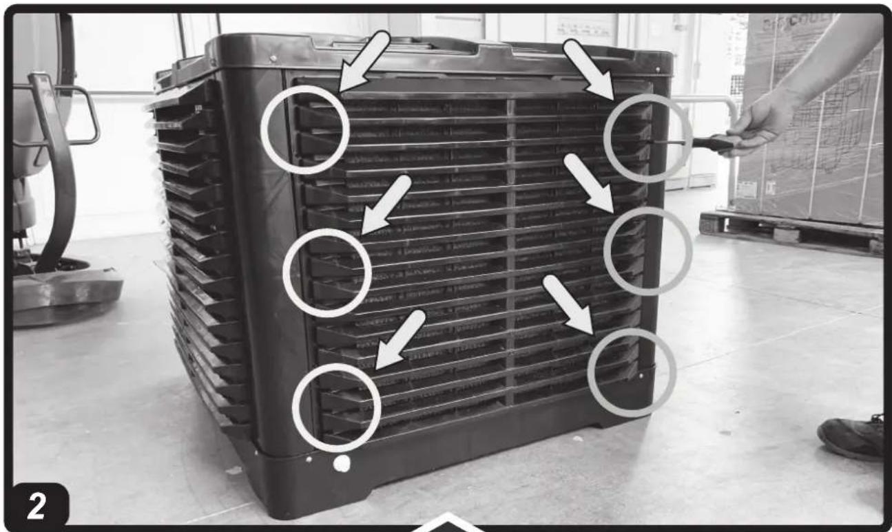
NOTE: TO ACCESS THE INTERNAL PARTS OF THE COOLER, REMOVE THE SCREWS AND EVAPORATION PANELS,
PLACE THEM ON THE SIDES OF THE APPLIANCE (Pic. 2).
▶▶3.1. HANDLING
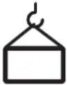
Handle the cooler with the utmost care, moving it horizontally.
▶▶3.2. PRE-INSTALLATION AND INSTALLATION METHOD
(Pic. 3)
During installation, the electrical connection, water connection, use and maintenance of the cooler, comply with all local regulations and standards in force.
▶3.2.1. The cooler must be installed on a stable and level structure, so as to prevent any risk (the structure and the plugs must be adequate to support the weight of the appliance).
▶3.2.2. Install the cooler in well ventilated areas.
▶3.2.3. The cooler can only be installed outside (on the roof or on the wall).
▶3.2.4. Install the cooler away from fireplaces, heat sources and possible sparks, in order to prevent serious damage.
▶3.2.5. Do not drill screws or tie rods into the cooler during installation.
▶3.2.6. The minimum installation distance between the cooler and walls or other objects is 0.5 m (ensure suitable spaces for maintenance around the cooler).
▶▶3.3. DUCTING METHOD
By connecting a conduit to the cooler, the outgoing air can be carried to where cooling is required.
It is crucial for the entire ducting conduit to be designed and structured correctly.
▶3.3.1. Use conduits of suitable section (the average air speed inside the conduit is 3-6 m/s).
▶3.3.2. The ducting should be as short as possible.
▶3.3.3. Do not install the duct with elbow bends.
▶3.3.4. Do not branch the air flow into several conduits.
NOTE: WE RECOMMEND USING CONDUITS MADE OF GALVANISED SHEET METAL, PLASTIC OR FIBREGLASS.
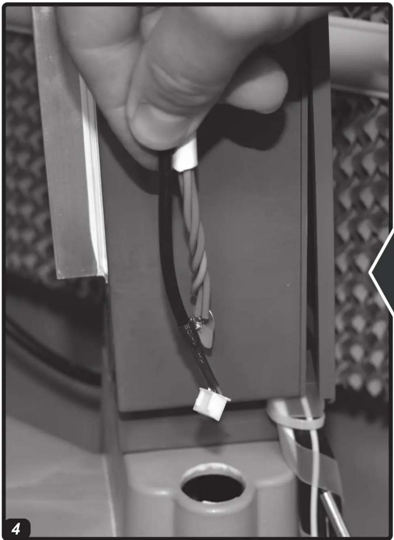
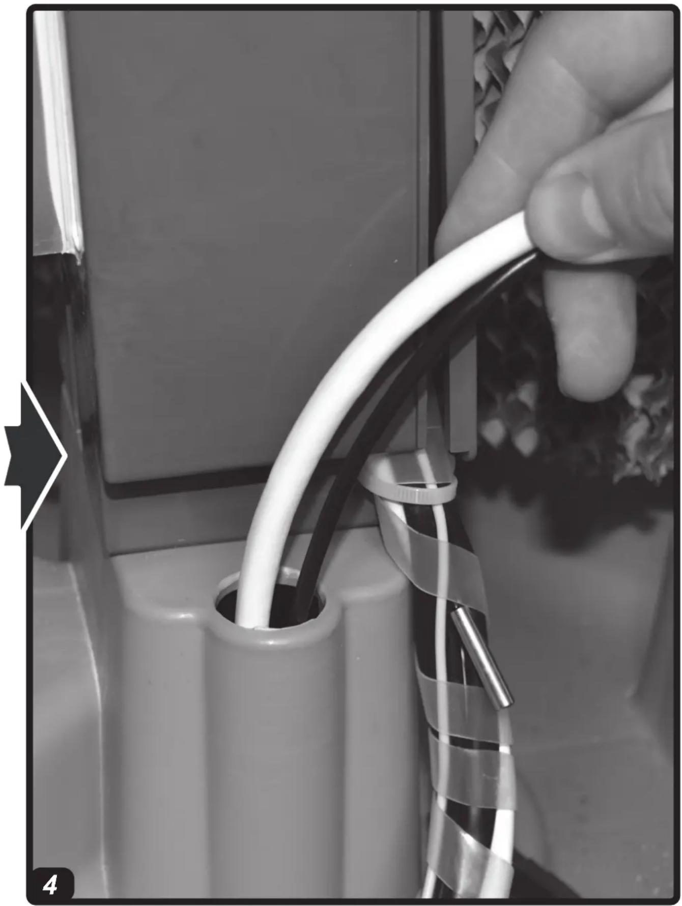
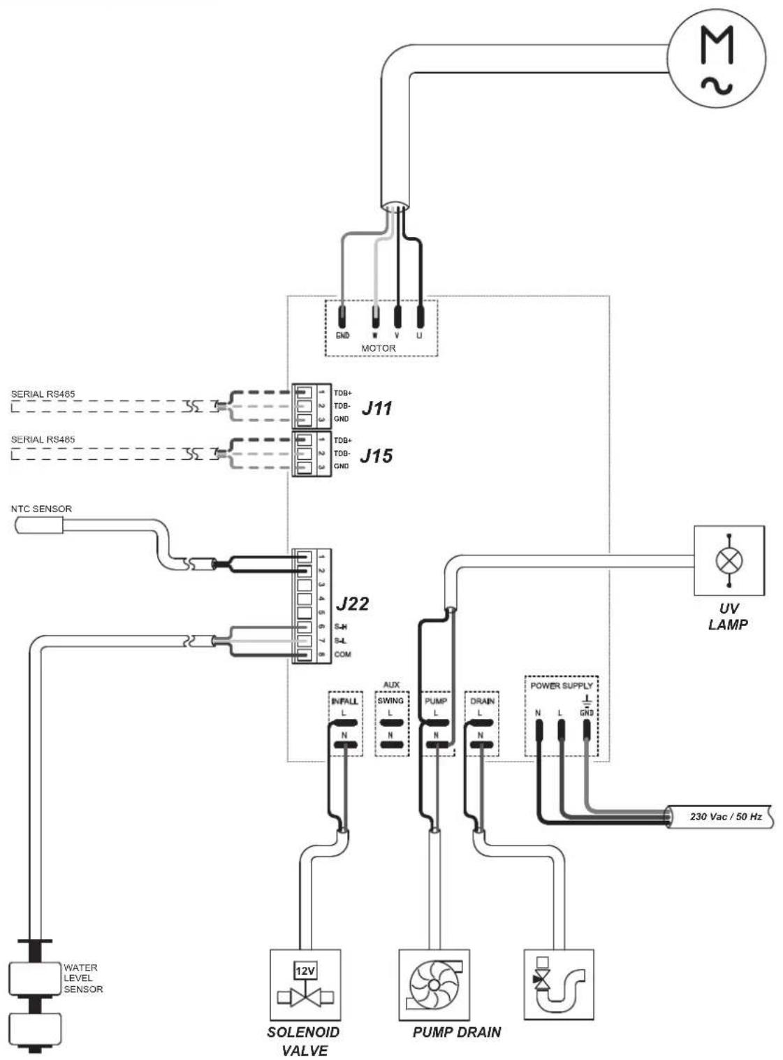
▶▶3.4. CONNECTION TO THE ELECTRICITY MAINS AND CONNECTION OF THE PROBE
IMPORTANT: THE POWER SUPPLY AND CONNECTION LINE MUST BE INSTALLED BY A QUALIFIED TECHNICIAN USING SUITABLE DEVICES AND INSTRUMENTS, IN ACCORDANCE WITH NATIONAL REGULATIONS AND THE STANDARDS IN FORCE.
▶3.4.1. By removing the screws on the side of the cooler you have access to the interior of the appliance (Pic. 2).
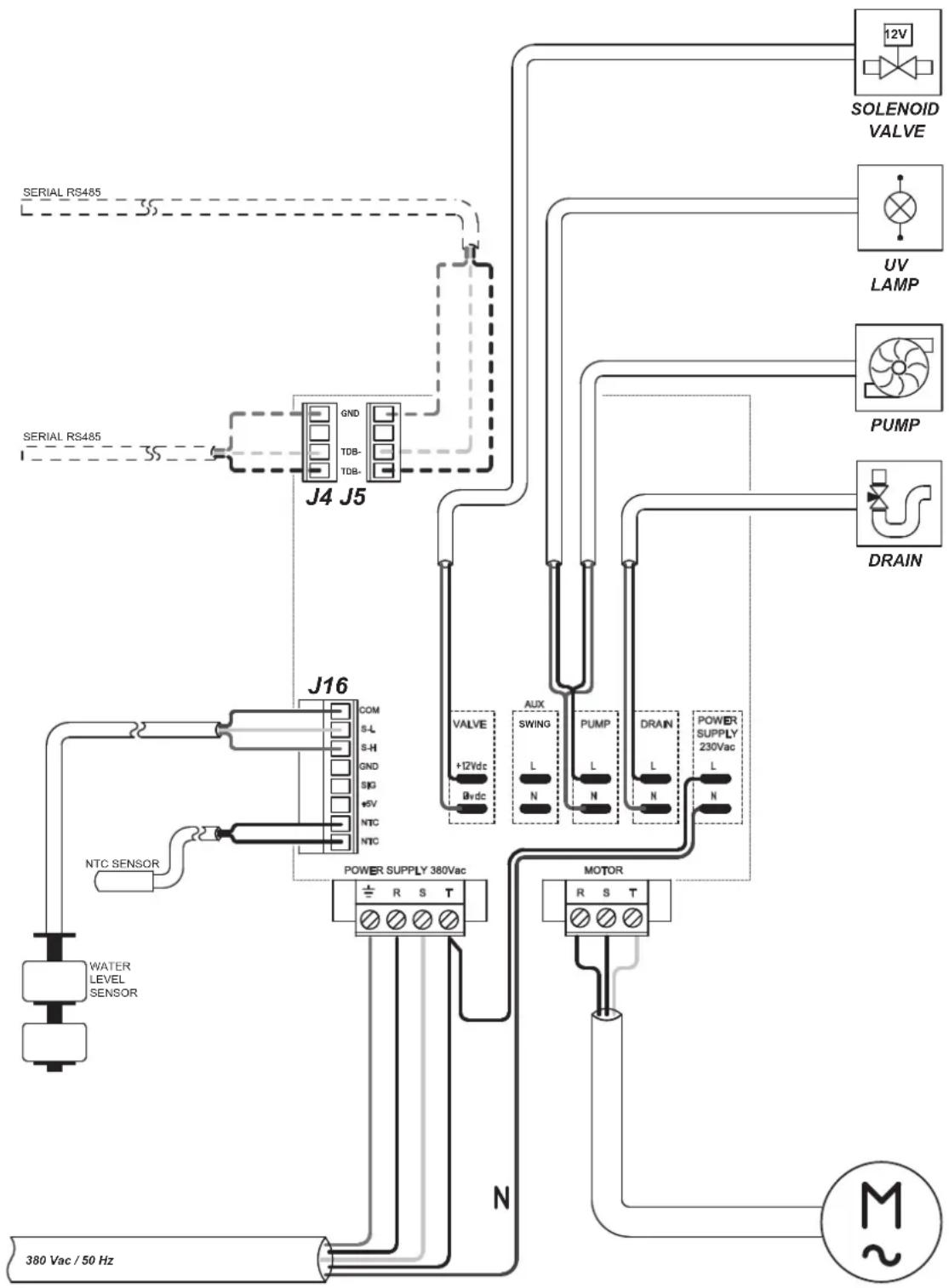
▶3.4.2. Feed the cables (power cable, serial connection cable, probe cable and solenoid valve cable) through the hole near the electrical panel on the bottom of the cooler (Pic. 4).
▶3.4.3. Only connect and power the cooler with the voltage and frequency specified on the nameplate and with cables of suitable section.
▶3.4.4. Correct operation requires the cooler to be earthed properly.
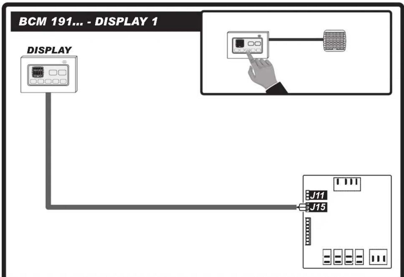
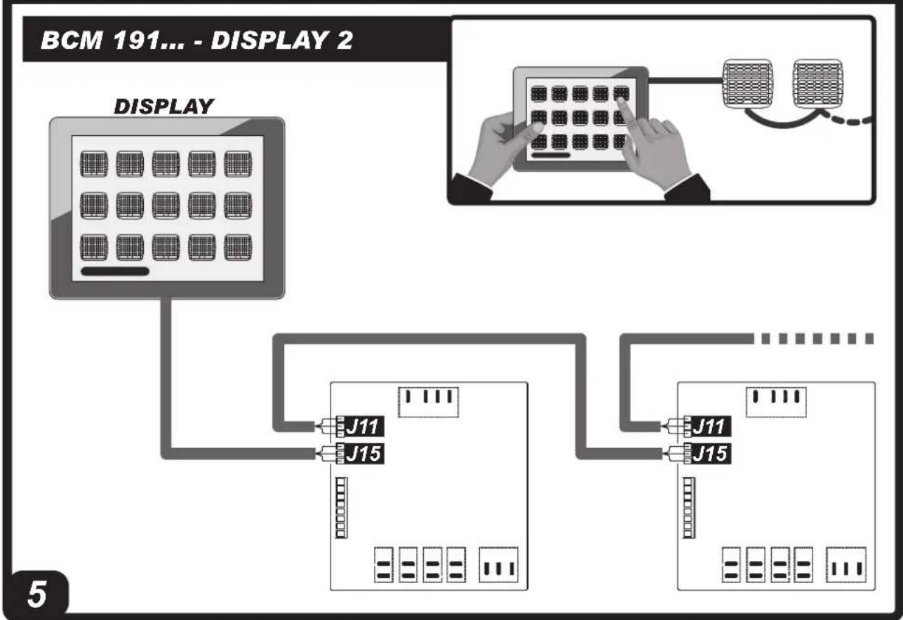
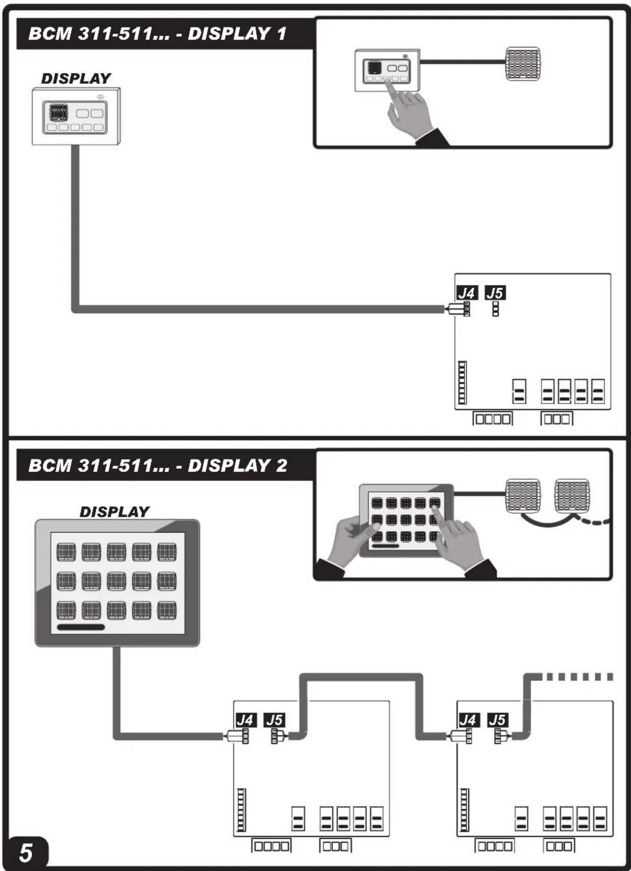
▶3.4.5. Connect the display to the serial cable (Pic. 5).
▶3.4.6. Connect the temperature / humidity probe cable (based on the model) to the electronic panel (Pic. 5).
▶3.4.7. Connect the solenoid valve cable to the electrical panel (Pic. 5).
NOTE: MAKE SURE THE POLARITIES ARE FOLLOWED WHEN CONNECTING TO THE MAINS. WE RECOMMEND USING A SUITABLE RESIDUAL CURRENT DEVICE (SEE NAMEPLATE).
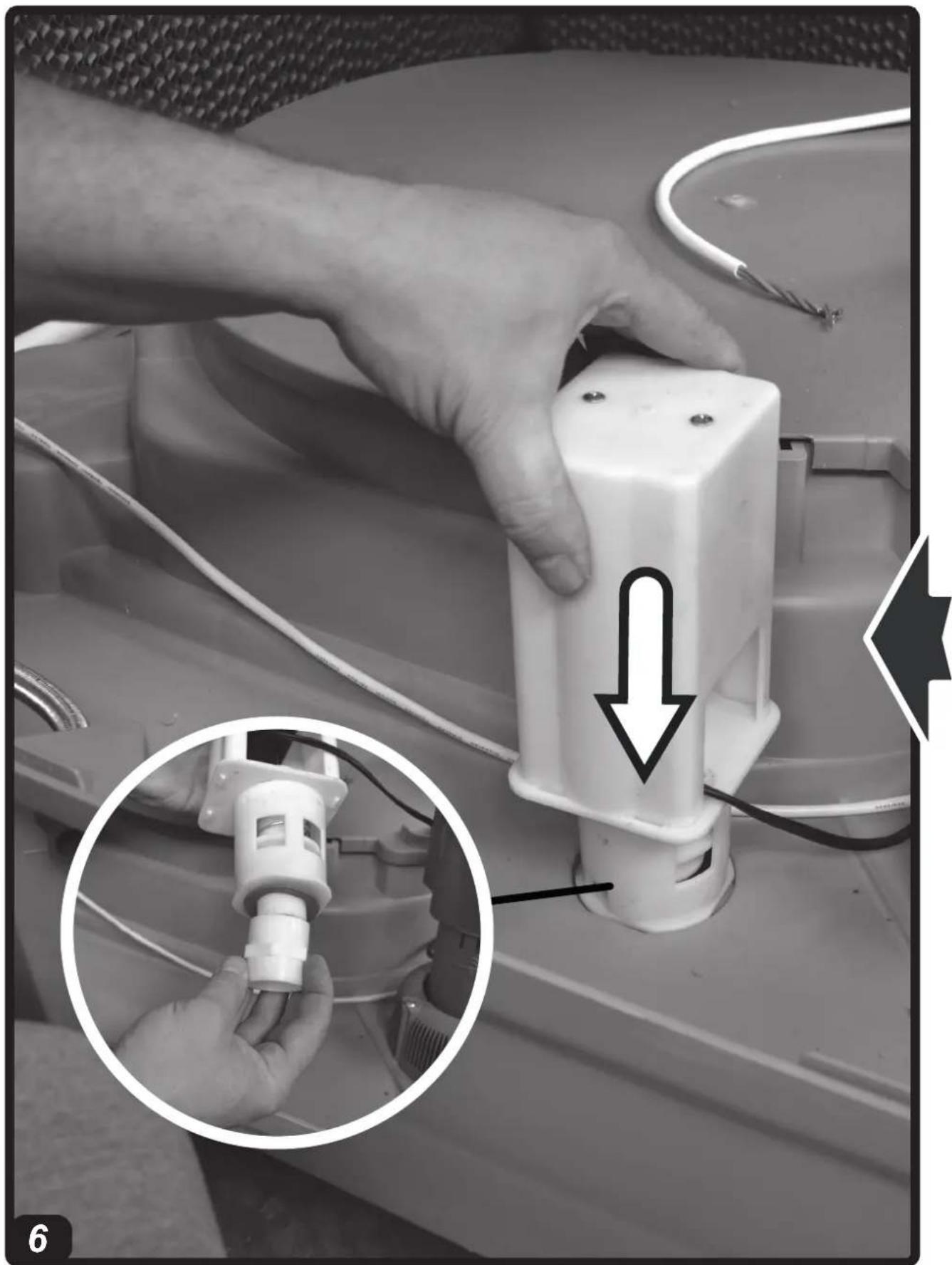
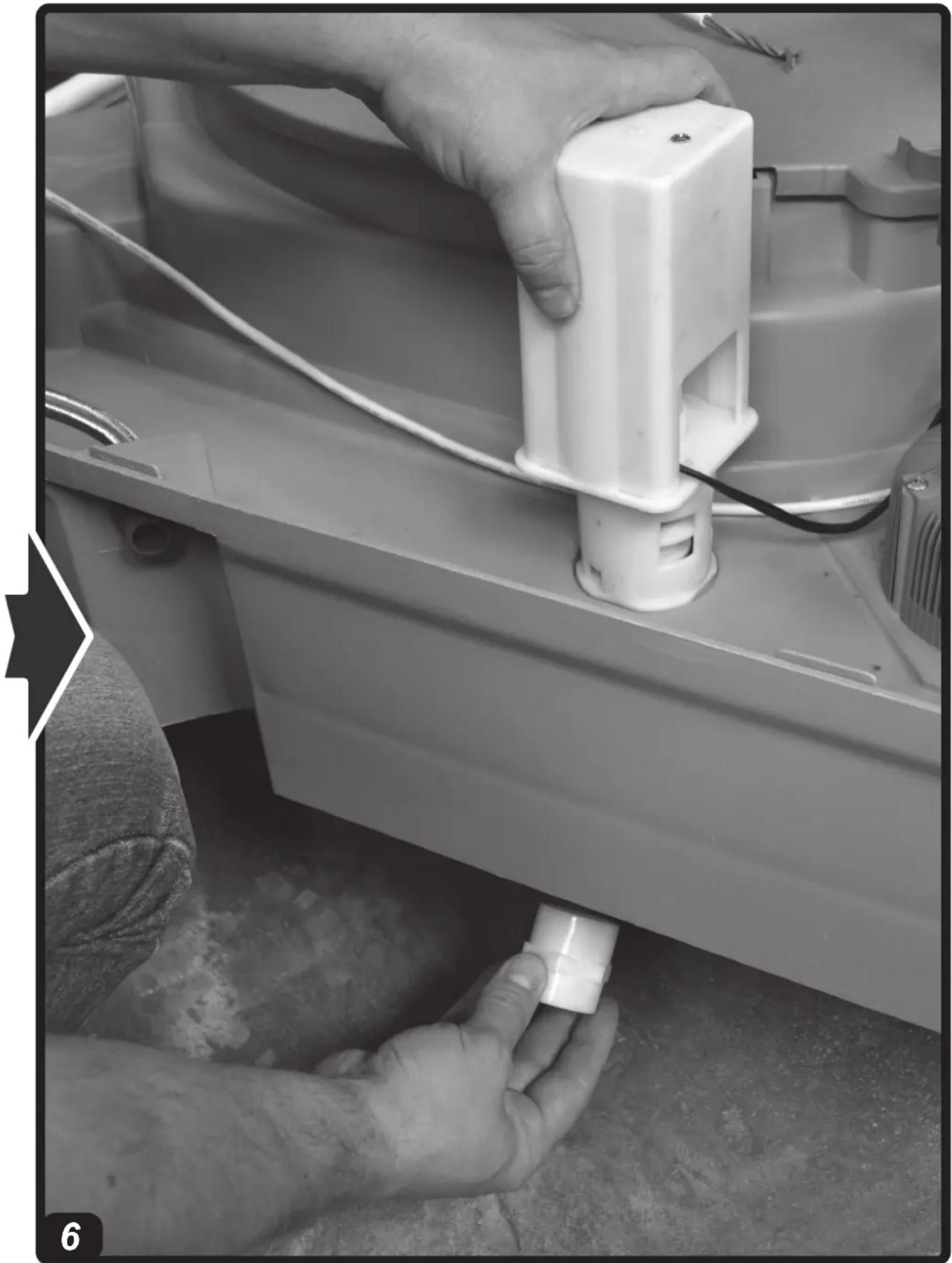
▶▶3.5. INSTALLING THE DRAIN VALVE
(Pic. 6)
At the base of the cooler, to drain water from the tank, the cooler is equipped with a drain valve.
At the time of purchase, the drain valve comes in the kit supplied.
To install the valve you must:
▶3.5.1. Remove the nut installed at the base of the valve.
▶3.5.2. Insert the valve into its seat (located at the base of the cooler).
▶3.5.3. Screw the nut back onto the valve.
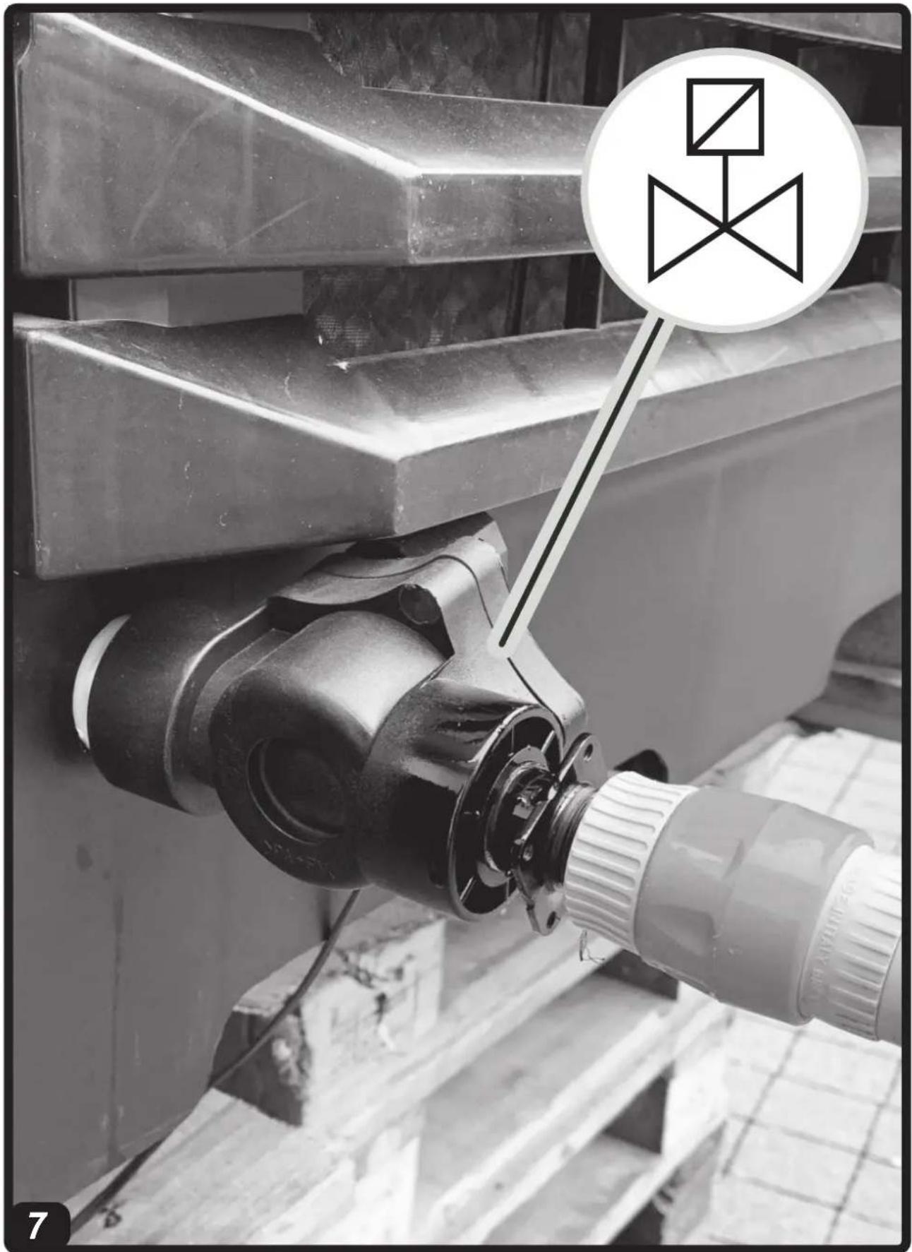
▶▶3.6. CONNECTING TO THE WATER MAINS
(Pic. 7)
IMPORTANT: ONLY FEED THE COOLER WITH CLEAN WATER.
IMPORTANT: THE COOLER CAN WITH- STAND A MAXIMUM WATER INLET PRESSURE OF 3 BAR. THE PIPES AND FITTINGS USED FOR THE WATER SUPPLY MUST BE OF ADEQUATE SECTION AND STRUCTURE (IF THE PRESSURE OF THE WATER MAINS IS HIGH, WE RECOMMEND USING A PRESSURE REDUCER AND A METAL MESH PIPE).
▶3.6.1. Connect the cooler to the water mains by using the threaded fitting and the solenoid valve.
▶3.6.2. Connect the solenoid valve to the electrical panel, by feeding the electrical cables through the hole near the electrical panel on the bottom of the cooler.
▶3.6.3. Make sure that there are no water leaks in the circuit before commissioning.
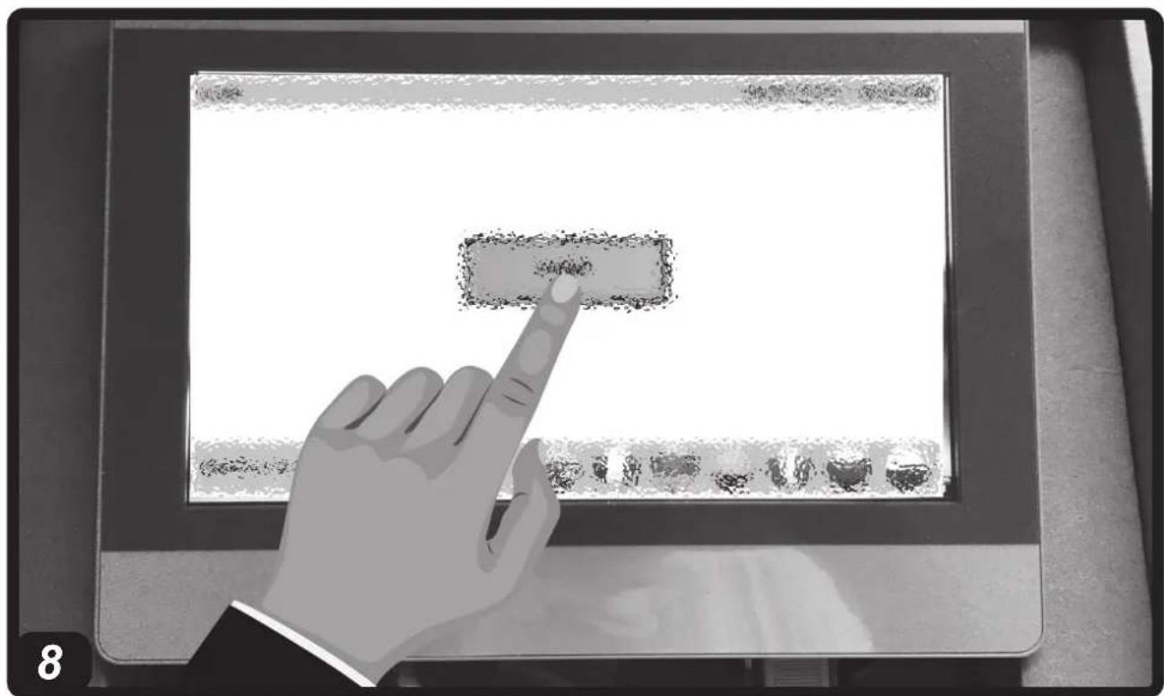
▶▶3.7. BASIC CONFIGURATION (Pic. 8)
IMPORTANT: USE A CABLE WITH SPECIFIC CHARACTERISTICS FOR THE SYSTEM TO WORK CORRECTLY (SEE THE TECHNICAL DATA TABLE).
IMPORTANT: THE BASIC CONFIGURATION OF THE COOLER MUST BE CAR-
RIED OUT FROM THE DISPLAY AFTER HAVING ASSIGNED A UNIQUE ADDRESS TO EACH MACHINE DURING INSTALLATION.
▶3.7.1. Log in and access the MAIN menu.
▶3.7.2. Use the CONFIG menu to map the system, showing which coolers are present in the 31 possible.
▶3.7.3. From the MAIN menu select all the coolers in the system (one cooler at a time), by accessing the relevant menu, and set:
1- INDIVIDUAL OR AREA OPERATING MODE:
-INDIVIDUAL OPERATION:
Autonomous operation that requires the presence of the probe.
-ARE OPERATION:
Overall logic (assign one of the 4 possible relevant AREAS) and define a “LEADER” machine within each AREA, which must be equipped with a temperature / humidity probe (based on the model). The “SLAVE” coolers do not need a probe to operate.
2 - MODE (COOLING / VENTILATION / INTAKE / CLEANING):
Select the button according to mode you want to set.
3 - HOURLY SETTING:
-Select AUTO in the TIMER box to set the hourly setting (the TIMER button is activated).
-Select MAN in the TIMER box to manually set the cooler on and off.
4 - OPERATING MODES WITH TEMPERATURE OR HUMIDITY LIMITS (BASED ON THE MODEL):
Use the specific drop-down menu, based on the model, to choose the temperature or humidity as a reference parameter. Selecting LOCAL defines the “LEADER” cooler of an area; similarly, selecting AREA defines a “SLAVE” cooler. Moving the cursor to LIMIT allows you to set the reference value for the temperature or humidity (based on the model).
5 - MOTOR ROTATION SPEED:
-Use the arrow button (right direction) to increase the rotation speed.
-Use the arrow button (left direction) to decrease the rotation speed.
▶3.7.4. All parameters must be set if the cooler is configured for “INDIVIDUAL” or “LEADER” mode. If the cooler is configured for “SLAVE” mode, the “LEADER” device configuration of the relevant area is implemented.
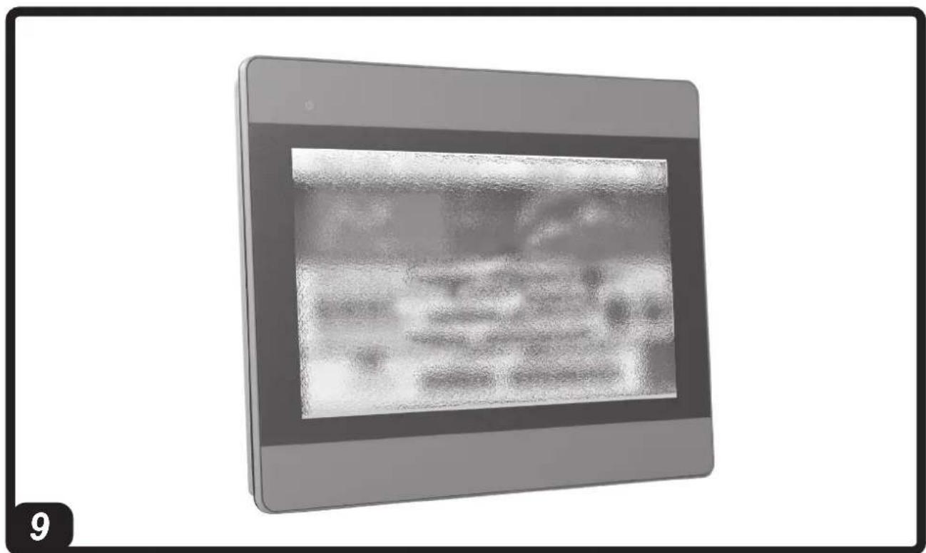
▶▶▶4. OPERATION
(Pic. 9)
WARNING: Carefully read the “SAFETY INFORMATION” before switching on the cooler.
WARNING: Only use clean water to prevent failures or other anomalies.
WARNING: Verify if your electronic system is earthed correctly. Connection to the electrical mains must be carried out in compliance with the national standards in force. Only power the appliance the with voltage and frequency as specified on the nameplate.
IMPORTANT: The cooler is equipped with a water drain, located at the base of the appliance. The cooler will completely drain the water from the tank, executing a wash cycle (the automatic drain time must be set by the user). During the winter season or in the event of a long period of inactivity, leave the circuit and water tank empty.
For correct operation, refer to the specific manual attached to the display.
▶▶▶5. CLEANING AND MAINTENANCE
WARNING: BEFORE CARRYING OUT ANY MAINTENANCE OR REPAIRS, DISCONNECT THE APPLIANCE FROM THE MAINS POWER AND WATER SUPPLY.
Depending on the environment where the appliance is used, dust, dirt, etc. can affect the performance of the cooler. We therefore recommend cleaning (never clean with a high pressure water jet) the outside of the cooler with a soft cloth, removing any obstructions from the air vents.
IMPORTANT:
-The cooler tank must be emptied and sanitised periodically depending on the use.
-The cooling pad surfaces must be periodically inspected and sanitised depending on the use.
-For sanitation operations, biocidal products that comply with European regulation no. 582/2012 must be used.
-If present, have the UV lamp checked and cleaned once a year by the service center.
▶▶▶6. TROUBLESHOOTING
| FAULT CAUSE SOLUTION | ||
| The control panel does not work | 1. No power supply2. Defective equipment | 1a. Make sure that the device is connected to the power supply1b. Contact a support centre2. Contact a support centre |
| There is no air flow or it is very low | 1. Obstructed air vents2. Defective equipment | 1a. Remove any objects from the air vent1b. Contact a support centre2. Contact a support centre |
| The device does not respond to the commands | 1. No communication 1a. Check | that the serial cable is connected correctly1b. Contact a support centre |
| The device leaks water | 1. The water supply pipe is loose2. The water drain is dirty3. The tank leaks4. The panel is dripping | 1. Tighten the fitting2. Contact a support centre3. Contact a support centre4. Contact a support centre |
SOMMARIO PARAGRAFI SOMMARIO PARAGRAFI
▶▶3.6. RACCORDEMENT AU RÉSEAU HYDRIQUE
(Fig. 7)
IMPORTANT : ALIMENTER LE RAFRAÎ-CHISSEUR SEULEMENT AVEC DE L'EAU PROPRE.
IMPORTANT : LE RAFRAÎCHISSEUR PEUT SUPPORTER UNE PRESSION MAXIMUM D'ENTRÉE D'EAU DE 3 BAR. LES CONDUITES ET LES RACCORDS UTILISÉS POUR L'ALIMENTATION HYDRIQUE DOIVENT ÊTRE DE SECTION ET DE STRUCTURE ADÉQUATES (SI LA PRESSION DU RÉSEAU HYDRIQUE EST ÉLEVÉE, IL EST CONSEILLÉ D'UTILISER UN RÉDUCTEUR DE PRESSION ET UN TUYAU AVEC MAILLE MÉTALLIQUE).
▶▶3.7. BASISCONFIGURATIE (Afb. 8)
BELANGRIJK: GEBRUIK VOOR DE JUIS-TE WERKING VAN DE INSTALLATIE EEN KABEL MET SPECIFIEKE KENMERKEN (ZIE TABEL TECHNISCHE GEGEVENS).
BELANGRIJK: DE BASISCONFIGURATIE VAN DE KOELER WORDT UITGEVOERD VANAF HET DISPLAY NA AAN ELKE MACHINE EEN UNIEK ADRES TE HEBBEN TOEGEWEZEN IN DE INSTALLATIEFASE.
▶▶▶6. DRIFTSPROBLEMER
▶▶3.2. INSTALACJA WSTĘPNA I SPO- SÓB INSTALACJI
(Rys. 3)
▶▶3.2. PŘEDINSTALACE A ZPŮSOB INSTALACE
(Obr. 3)
BCM 191AB - BCM 191AL - BCM 191AU BCM 311AB - BCM 311AU BCM 511AB - BCM 511AU
We declare that it is compliant with: - Si dichiara che è conforme a: - Es wird als konform mit den folgenden Normen erklärt: - Se declara que está en conformidad con: - Nous déclarons sa conformité à: - Hierbij wordt verklaard dat het product conform is met: - Declara-se que está em conformidade com: - Vi erklærer at produktet er i overensstemmelse med: - Vakuutetaan olevan yhdenmukainen: - Man erklærer at apparatet er i overensstemmelse med: - Härmed intygas det att produkten är förenlig med följande: - Oświadcza się, że jest zgodny z: - Заявляем о соответствии требованиям: - Prohlašuje se, że je v souladu s: - Kijelentjük, hogy a termék megfelel az alábbiaknak: - Izpolnjuje zahteve: - Aşağıdaki standartlara uygun olduğunu beyan ederiz: - Izjavljuje se da je u skladu s: - Pareiškiame, kad atitinka: - Tiek deklarēts, ka atbilst: - Käesolevaga deklareeritakse, et toode vastab: - Declarăm că este conform următoarelor: - Prehlasuje sa, že je v súlade s: - Декларира се че отговаря на: - Відповідає вимогам: - Izjavljuje se da je u skladu s: - Δηλώνουμε ότι είναι σύμφωνο με: - 兹证明符合:
2014/30/EU, 2014/35/EU, 2011/65/EU
EN 61000-3-2:2014, EN 61000-3-3:2013, EN 55014-1:2006/A2:2011, EN 55014-2:2015, EN 60335-1:2012/A11:2014, EN 60335-2-80:2003/A2:2009, EN 60335-2-98:2003/A2:2008
Pastrengo, 2024

▶en - DISPOSAL OF THE PRODUCT
-This product has been designed and manufactured with top-quality materials and components, which can be re-cycled and re-used. -When a crossed-wheely bin symbol is attached to the product, it means that the product is protected by the, 2012/19/UE European Directive.
-Please obtain information regarding the local differentiated collection system for electrical and electronic products.
-Respect local Standards in force and do not dispose of old products as normal domestic waste. Correct disposal of the product helps to prevent possible negative consequences for health, the environment and mankind.
▶pl - UTYLIZACJA PRODUKTU
natural_image
Abstract geometric composition with yellow and black blocks (no text or symbols)Dantherm S.p.A.
Via Gardesana 11
37010 Pastrengo (VR)
Italy
t.: +39 045 6770533
e.: info.it@danthermgroup.com

DOWNLOAD CATALOGUE

SEND US YOUR FEEDBACK

REGISTER FOR 3-YEAR WARRANTEE


- USER AND MAINTENANCE MANUAL
- NOTE:
- ▶▶▶1. INFORMATION ON SAFETY
- ▶▶▶2. UNPACKING
- ▶▶▶3. ASSEMBLY AND INSTALLATION (ONLY FOR QUALIFIED PERSONNEL)
- ▶▶3.1. HANDLING
- ▶▶3.2. PRE-INSTALLATION AND INSTALLATION METHOD
- (Pic. 3)
- ▶▶3.3. DUCTING METHOD
- ▶▶3.4. CONNECTION TO THE ELECTRICITY MAINS AND CONNECTION OF THE PROBE
- ▶▶3.5. INSTALLING THE DRAIN VALVE
- ▶▶3.6. CONNECTING TO THE WATER MAINS
- ▶▶3.7. BASIC CONFIGURATION (Pic. 8)
- - MOTOR ROTATION SPEED:
- ▶▶▶4. OPERATION
- ▶▶▶5. CLEANING AND MAINTENANCE
- IMPORTANT:
- SOMMARIO PARAGRAFI SOMMARIO PARAGRAFI
- ▶▶3.6. RACCORDEMENT AU RÉSEAU HYDRIQUE
- ▶▶3.7. BASISCONFIGURATIE (Afb. 8)
- BELANGRIJK: GEBRUIK VOOR DE JUIS-TE WERKING VAN DE INSTALLATIE EEN KABEL MET SPECIFIEKE KENMERKEN (ZIE TABEL TECHNISCHE GEGEVENS).
- ▶▶3.2. INSTALACJA WSTĘPNA I SPO- SÓB INSTALACJI
- ▶▶3.2. PŘEDINSTALACE A ZPŮSOB INSTALACE
- BCM 191AB - BCM 191AL - BCM 191AU BCM 311AB - BCM 311AU BCM 511AB - BCM 511AU
- ▶en - DISPOSAL OF THE PRODUCT
- ▶pl - UTYLIZACJA PRODUKTU
Brand : Master
Model : BCM 191
Category : Air Conditioning