DDG461Z - Uncategorized MAKITA - Free user manual and instructions
Find the device manual for free DDG461Z MAKITA in PDF.
Download the instructions for your Uncategorized in PDF format for free! Find your manual DDG461Z - MAKITA and take your electronic device back in hand. On this page are published all the documents necessary for the use of your device. DDG461Z by MAKITA.
USER MANUAL DDG461Z MAKITA
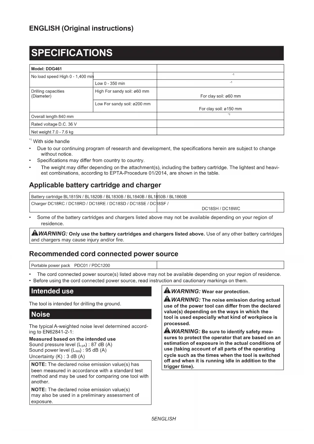
Fig.16 Fig.17 Fig.185 ENGLISH ENGLISH (Original instructions) SPECIFICATIONS Model: DDG461 No load speed High 0 - 1,400 min
- Specicationsmaydierfromcountrytocountry.
- Theweightmaydierdependingontheattachment(s),includingthebatterycartridge.Thelightestandheavi- estcombinations,accordingtoEPTA-Procedure01/2014,areshowninthetable. Applicable battery cartridge and charger Battery cartridge BL1815N/BL1820B/BL1830B/BL1840B/BL1850B/BL1860B Charger DC18RC/DC18RD/DC18RE/DC18SD/DC18SE/DC18SF/ DC18SH/DC18WC
- Someofthebatterycartridgesandchargerslistedabovemaynotbeavailabledependingonyourregionof residence.
WARNING: Only use the battery cartridges and chargers listed above.Useofanyotherbatterycartridges
- Before using the cord connected power source, read instruction and cautionary markings on them. Intended use The tool is intended for drilling the ground. Noise ThetypicalA-weightednoiseleveldeterminedaccord- ingtoEN62841-2-1: Measured based on the intended use Sound pressure level (L
):95dB(A) Uncertainty(K):3dB(A) NOTE: The declared noise emission value(s) has beenmeasuredinaccordancewithastandardtest methodandmaybeusedforcomparingonetoolwith another. NOTE: The declared noise emission value(s) mayalsobeusedinapreliminaryassessmentof exposure.
WARNING: Wear ear protection.
WARNING: The noise emission during actual
use of the power tool can dier from the declared value(s) depending on the ways in which the tool is used especially what kind of workpiece is processed.
WARNING: Be sure to identify safety mea-
sures to protect the operator that are based on an estimation of exposure in the actual conditions of use (taking account of all parts of the operating cycle such as the times when the tool is switched o and when it is running idle in addition to the trigger time).6 ENGLISH Vibration Thevibrationtotalvalue(tri-axialvectorsum)deter- minedaccordingtoEN62841-1: Measured based on the intended use Vibrationemission(a h,D ):2.5m/s
NOTE:Thedeclaredvibrationtotalvalue(s)hasbeen measured in accordance with a standard test method andmaybeusedforcomparingonetoolwithanother. NOTE:Thedeclaredvibrationtotalvalue(s)mayalso beusedinapreliminaryassessmentofexposure.
WARNING: The vibration emission during
actual use of the power tool can dier from the declared value(s) depending on the ways in which the tool is used especially what kind of workpiece is processed.
WARNING: Be sure to identify safety mea-
sures to protect the operator that are based on an estimation of exposure in the actual conditions of use (taking account of all parts of the operating cycle such as the times when the tool is switched o and when it is running idle in addition to the trigger time). Declarations of Conformity For European countries only TheDeclarationsofconformityareincludedinAnnexA to this instruction manual. SAFETY WARNINGS General power tool safety warnings WARNING Read all safety warnings, instruc- tions, illustrations and specications provided with this power tool. Failure to follow all instructions listed belowmayresultinelectricshock,reand/orserious injury. Save all warnings and instruc- tions for future reference. The term "power tool" in the warnings refers to your mains-operated(corded)powertoolorbattery-operated (cordless) power tool. Cordless Earth Auger safety warnings
1. Hold the tool with both hands at the intended
handles. Loss of control can cause personal injury.
3. Hold the power tool by insulated gripping
surfaces, when performing an operation where the digging accessory may contact hidden wiring. Digging accessory contacting a "live" wire may make exposed metal parts of the power tool "live" and could give the operator an electric shock.
4. Never operate at higher speed than the maxi-
mum speed rating of the earth augering bit.At higherspeeds,thebitislikelytobendifallowed to rotate freely without contacting the workpiece, resultinginpersonalinjury.
5. Always start earth augering at low speed and
with the earth augering tip in contact with the ground. Athigherspeeds,thebitislikelytobend if allowed to rotate freely without contacting the ground,resultinginpersonalinjury.
6. Apply pressure only in direct line with the bit
and do not apply excessive pressure. Bits can bendcausingbreakageorlossofcontrol,resulting inpersonalinjury.
7. The outside diameter of the auger bit must be
within the drilling capacity specied in this instruction manual.Incorrectlysizedaugerbit cannotbeadequatelycontrolled.
8. Always be sure you have a rm footing. Be
sure no one is below when using the tool in high locations.
9. Hold the tool rmly.
10. Keep hands away from rotating parts.
11. Do not leave the tool running. Operate the tool
only when hand-held.
12. Do not touch the auger bit immediately after
operation; it may be extremely hot and could burn your skin.
13. Some material contains chemicals which may
be toxic. Take caution to prevent dust inhala- tion and skin contact. Follow material supplier safety data.
14. If the auger bit cannot be loosened even you
remove the auger pin, use pliers to pull it out. Insuchacase,pullingouttheaugerbitbyhand mayresultininjurybyitssharpedge.
15. If something wrong with the tool such as
abnormal sounds, stop operating immediately and ask your local Makita Service Center for repair.
16. Before operation, make sure that there is no
buried object such as electric pipe, water pipe or gas pipe in the ground. Otherwise, the tool may touch them, resulting an electric shock, elec- trical leakage or gas leak. SAVE THESE INSTRUCTIONS.
WARNING: DO NOT let comfort or familiarity
with product (gained from repeated use) replace strict adherence to safety rules for the subject product. MISUSE or failure to follow the safety rules stated in this instruction manual may cause serious personal injury.7 ENGLISH Important safety instructions for battery cartridge
Before using battery cartridge, read all instruc- tions and cautionary markings on (1) battery charger, (2) battery, and (3) product using battery.
2. Do not disassemble or tamper with the battery
cartridge.Itmayresultinare,excessiveheat, or explosion.
3. If operating time has become excessively
shorter, stop operating immediately. It may result in a risk of overheating, possible burns and even an explosion.
If electrolyte gets into your eyes, rinse them out with clear water and seek medical attention right away. It may result in loss of your eyesight.
5. Do not short the battery cartridge:
(1) Do not touch the terminals with any con- ductive material. (2) Avoid storing battery cartridge in a con- tainer with other metal objects such as nails, coins, etc. (3) Do not expose battery cartridge to water or rain. A battery short can cause a large current ow, overheating, possible burns and even a breakdown.
6. Do not store and use the tool and battery car-
tridge in locations where the temperature may reach or exceed 50 °C (122 °F).
7. Do not incinerate the battery cartridge even if
it is severely damaged or is completely worn out. The battery cartridge can explode in a re.
8. Do not nail, cut, crush, throw, drop the battery
cartridge, or hit against a hard object to the battery cartridge. Such conduct may result in a re,excessiveheat,orexplosion.
9. Do not use a damaged battery.
The contained lithium-ion batteries are subject to the Dangerous Goods Legislation requirements. Forcommercialtransportse.g.bythirdparties, forwarding agents, special requirement on pack- agingandlabelingmustbeobserved. Forpreparationoftheitembeingshipped,consult- ing an expert for hazardous material is required. Pleasealsoobservepossiblymoredetailed national regulations. Tapeormaskoopencontactsandpackupthe batteryinsuchamannerthatitcannotmove around in the packaging.
11. When disposing the battery cartridge, remove
it from the tool and dispose of it in a safe place. Follow your local regulations relating to disposal of battery.
12. Use the batteries only with the products
specied by Makita.Installingthebatteriesto non-compliantproductsmayresultinare,exces- sive heat, explosion, or leak of electrolyte.
13. If the tool is not used for a long period of time,
the battery must be removed from the tool.
14. During and after use, the battery cartridge may
take on heat which can cause burns or low temperature burns. Pay attention to the han- dling of hot battery cartridges.
15. Do not touch the terminal of the tool imme-
diately after use as it may get hot enough to cause burns.
16. Do not allow chips, dust, or soil stuck into the
terminals, holes, and grooves of the battery cartridge.Itmaycauseheating,catchingre, burstandmalfunctionofthetoolorbatterycar- tridge,resultinginburnsorpersonalinjury.
17. Unless the tool supports the use near
high-voltage electrical power lines, do not use the battery cartridge near high-voltage electri- cal power lines. It may result in a malfunction or breakdownofthetoolorbatterycartridge.
18. Keep the battery away from children.
SAVE THESE INSTRUCTIONS. CAUTION: Only use genuine Makita batteries. Useofnon-genuineMakitabatteries,orbatteriesthat havebeenaltered,mayresultinthebatterybursting causingres,personalinjuryanddamage.Itwill also void the Makita warranty for the Makita tool and charger. Tips for maintaining maximum battery life
1. Charge the battery cartridge before completely
discharged. Always stop tool operation and charge the battery cartridge when you notice less tool power.
Never recharge a fully charged battery cartridge. Overcharging shortens the battery service life.
Charge the battery cartridge with room tempera- ture at 10 °C - 40 °C (50 °F - 104 °F). Let a hot battery cartridge cool down before charging it.
4. When not using the battery cartridge, remove
it from the tool or the charger.
5. Charge the battery cartridge if you do not use
it for a long period (more than six months). INITIAL SETTING CAUTION: Always be sure that the tool is switched o and the battery cartridge is removed before carrying out any work on the tool. PARTS DESCRIPTION ►Fig.1 1 Main tool 2 Front handle3 Side handle 4 Reaction receiver5 Bolt 6 Wrench Specications of the bolt / wrench - Nominal diameter oftheboltWrench size (H)A M 12 10 mmB M 8 6 mmC M 6 5 mm8 ENGLISH Setting up tool CAUTION: Always be sure that the front handle, side handle and reaction receiver are installed securely before operation. NOTICE: Do not over tighten the bolts. It may damage the tool. Installing the side handle Removetheboltsshowninthegurefromthetool. Keeptheboltssothattheyarenotlost. ►Fig.2: 1. Bolt Placethesidehandleonthetool. Tightentheallfourboltstemporarily,andthensecurely tightentheboltsusingthewrench. ►Fig.3: 1. Side handle 2.BoltA3. Bolt B Installing the reaction receiver Placethereactionreceiversothatthebarofthereac- tion receiver comes to the left side of the operator. Adjustthepositionofthereactionreceiversothatthe axisofthespindleisinthecenteroftheoperator'sbody. Fastentheboltsrmly. ►Fig.4: 1. Bar of the reaction receiver 2. Bolt C FUNCTIONAL DESCRIPTION CAUTION: Always be sure that the tool is switched o and the battery cartridge is removed before adjusting or checking function on the tool. Indicating the remaining battery capacity Only for battery cartridges with the indicator ►Fig.5: 1. Indicator lamps 2.Checkbutton Pressthecheckbuttononthebatterycartridgetoindicatetheremain- ingbatterycapacity.Theindicatorlampslightupforafewseconds. Indicator lamps Remaining capacity Lighted O Blinking 75% to 100% 50% to 75% 25% to 50% 0% to 25% Charge the battery. Thebattery may have malfunctioned. NOTE: Depending on the conditions of use and the ambienttemperature,theindicationmaydierslightly from the actual capacity. NOTE:Therst(farleft)indicatorlampwillblinkwhen thebatteryprotectionsystemworks. Tool / battery protection system Thetoolisequippedwithatool/batteryprotectionsys- tem.Thissystemautomaticallycutsopowertothe motortoextendtoolandbatterylife.Thetoolwillauto- maticallystopduringoperationifthetoolorbatteryis placed under one of the following conditions: Overload protection Whenthetool/batteryisoperatedinamannerthat causesittodrawanabnormallyhighcurrent,thetool stopsautomatically.Inthissituation,turnthetoolo andstoptheapplicationthatcausedthetooltobecome overloaded. Then turn the tool on to restart. Overheat protection Whenthetool/batteryisoverheated,thetoolstops automatically.Inthissituation,letthetool/batterycool beforeturningthetoolonagain. Overdischarge protection Whenthebatterycapacityisnotenough,thetoolstops automatically.Inthiscase,removethebatteryfromthe toolandchargethebattery. Protections against other causes Protectionsystemisalsodesignedforothercauses that could damage the tool and allows the tool to stop automatically. Take all the following steps to clear the causes,whenthetoolhasbeenbroughttoatemporary halt or stop in operation.
2. Chargethebattery(ies)orreplaceit/themwith
rechargedbattery(ies).
3. Letthetoolandbattery(ies)cooldown.
Ifnoimprovementcanbefoundbyrestoringprotection system, then contact your local Makita Service Center. Main power switch
WARNING: When the tool is not in use, turn
the tool o and set the reversing switch lever in the neutral position to lock the trigger. Always be sure that the main power lamp goes out after you turn the tool o. Tostandbythetool,pressthemainpowerbuttonuntil themainpowerlamplightsup.Toturno,pressthe mainpowerbuttonagain. ►Fig.6: 1.Mainpowerbutton2. Main power lamp NOTE:Thistoolemploystheautopower-ofunction. To avoid unintentional start up, the main power switch will automatically shut down when the switch trigger isnotpulledforabout5minutesafterthemainpower switch is turned on.9 ENGLISH Switch action CAUTION: Before installing the battery car- tridge into the tool, always check to see that the switch trigger actuates properly and returns to the "OFF" position when released. ►Fig.7: 1. Switch trigger To start the tool, pull the switch trigger with the main powerswitchon.Toolspeedisincreasedbyincreas- ing pressure on the switch trigger. Release the switch trigger to stop. NOTE: The tool automatically stops if you keep pull- ingtheswitchtriggerforabout6minutes. Lighting up the front lamp CAUTION: Do not look in the light or see the source of light directly. ►Fig.8: 1. Lamp Pulltheswitchtriggertolightupthelamp.Thelamp keepsonlightingwhiletheswitchtriggerisbeingpulled. The lamp goes out approximately 10 seconds after releasing the switch trigger. NOTE: When the tool is overheated, the tool stops automaticallyandthelampstartsashing.Inthis case,releasetheswitchtrigger.Thelampturnsoin 5 minute(s). NOTE:Useadryclothtowipethedirtothelensof the lamp. Be careful not to scratch the lens of lamp, or it may lower the illumination. Reversing switch action CAUTION: Always check the direction of rotation before operation. CAUTION: Use the reversing switch only after the tool comes to a complete stop. Changing the directionofrotationbeforethetoolstopsmaydam- age the tool. CAUTION: When not operating the tool, always set the reversing switch lever to the neu- tral position. This tool has a reversing switch to change the direction of rotation. Depress the reversing switch lever from the AsideforclockwiserotationorfromtheBsideforcoun- terclockwise rotation. When the reversing switch lever is in the neutral posi- tion,theswitchlevercannotbepulled. ►Fig.9: 1. Reversing switch lever Automatic speed change function This tool has "high speed mode" and "high torque mode". The tool automatically changes the operation mode depending on the work load. When the work load is low, the tool will run in the "high speed mode" for quicker operation. When the work load is high, the tool will run in the "high torque mode" for powerful operation. ►Fig.10: 1. Mode indicator The mode indicator lights up in green when the tool is running in "high torque mode". If the tool is operated with excessive load, the mode indicatorwillblinkingreen.Themodeindicatorstops blinkingandthenlightsuporturnsoifyoureducethe load on the tool. Mode indicator status Operation mode On O Blinking High speed mode High torque mode Overload alert Speed change NOTICE: Use the speed change knob only after the tool comes to a complete stop. Changing the toolspeedbeforethetoolstopsmaydamagethetool. NOTICE: Always set the speed change knob carefully into the correct position. If you operate thetoolwiththespeedchangeknobpositionedhalf- waybetweentheposition1andtheposition2,the toolmaybedamaged. Twospeedrangescanbepreselectedwiththespeed changeknob. Tochangethespeed,depressthelockbuttonandturn thespeedchangeknobsothatthepointerpointstothe position 1 for low speed or the position 2 for high speed. ►Fig.11: 1.Lockbutton2.Pointer3.Speedchangeknob Torque limiter The torque limiter will actuate when a certain torque level is reached at the low speed setting (position 1). The motor will disengage from the output shaft. When thishappens,thetoolbitwillstopturning. Torestartthetool,liftthetoolbitoutoftheholeand then pull the switch trigger again. Accidental restart preventive function Alockoutfunctionforswitchtriggertopreventunin- tended operation. The tool will not start if you press the mainpowerbuttonwhilepullingtheswitchtrigger. To restart the tool, release the switch trigger and then pull it again.10 ENGLISH Electronic function The tool is equipped with the following electronic func- tions for easy operation. Electric brake Thistoolisequippedwithanelectricbrake.Ifthetool consistently fails to quickly cease to function after the switch trigger is released, have the tool serviced at a Makita service center. Soft start feature Thisfunctionallowsthesmoothstart-upofthetoolby limiting the start-up torque. Strap hole
WARNING: Do not use the strap hole for
any other purpose than hanging the tool or than anti-theft of the tool. Otherwisepersonalinjurymay occur. ►Fig.12: 1. Strap hole ASSEMBLY Installing or removing battery cartridge CAUTION: Always switch o the tool before installing or removing of the battery cartridge. CAUTION: Hold the tool and the battery car- tridge rmly when installing or removing battery cartridge.Failuretoholdthetoolandthebattery cartridgermlymaycausethemtoslipoyourhands andresultindamagetothetoolandbatterycartridge andapersonalinjury. ►Fig.13: 1. Red indicator 2. Button 3. Battery cartridge Toremovethebatterycartridge,slideitfromthetool whileslidingthebuttononthefrontofthecartridge. Toinstallthebatterycartridge,alignthetongueonthe batterycartridgewiththegrooveinthehousingandslip it into place. Insert it all the way until it locks in place with a little click. If you can see the red indicator as showninthegure,itisnotlockedcompletely. CAUTION: Always install the battery cartridge fully until the red indicator cannot be seen. If not, itmayaccidentallyfalloutofthetool,causinginjuryto you or someone around you. CAUTION: Do not install the battery cartridge forcibly. If the cartridge does not slide in easily, it is notbeinginsertedcorrectly. Mounting auger bit CAUTION: Always be sure that the tool is switched o and the battery cartridge is removed before carrying out any work on the tool. CAUTION: When attaching the auger bit to the spindle, make sure that the auger pin is locked and inspect the auger pin for any damages. CAUTION: When carrying the tool, remove the auger bit from the tool. Mounting auger bit on spindle NOTE:Theshapeandmechanismoftheaugerbit and the auger pin may vary depending on your auger bit. Aligntheholeonthespindlewiththeholeontheauger bit. Puttheaugerbitontothespindle. ►Fig.14: 1.Augerbit2. Spindle Fixtheaugerbitwiththeaugerpinandthesafetylock. ►Fig.15: 1.Augerpin2. Safety lock OPERATION CAUTION: This is a powerful tool which gen- erates high torque. It is important that the tool is securely held and properly braced. CAUTION: Before operating, check that there is no foreign matter (sand, dirt, etc.) stuck in the openings or moving parts. Work posture Maintaining proper operating position is one of the mostimportantandeectiveproceduresforcontrolling kickback. Keepproperpositioningbypracticingthefollowing points.
- Positionthetoolsothatthebarofthereaction receiver always contacts on the left side of your waist.
- Graspthehandleandthesidehandlewithboth hands.Wrapyourngersaroundthegripping areas, keeping the gripping areas cradled betweenyourthumbsandforengers.
- Keepyourbackasverticalaspossiblebybending the legs as required during the digging process.
- Stay alert to the torque reaction force of the tool. Alwayskeeptheoperatingpositionthatyoucan withstand the torque reaction force. ►Fig.16: 1. Handle 2. Side handle 3. Bar of the reac- tion receiver
WARNING: Avoid improper positioning. Do
not stand too far from the tool.Properreactionand controlmaynotbeachievedintheeventofkickback. ►Fig.1711 ENGLISH Digging operation CAUTION: Hold the tool rmly when operat- ing the tool. CAUTION: Keep your face and hands away from drilling attachments, such as an auger bit, any rotating parts and drill cutting waste during operation. CAUTION: When leaving the tool, such as during a break, do not leave the tool stabbed in the ground or lean it against a wall. Store the tool in a stable condition. NOTICE: When the rotation speed comes down extremely, reduce the load or stop the tool to avoid the tool damage. NOTICE: Pressing excessively on the tool will not speed up the digging. In fact, this excessive pressure will only serve to damage the tip of the augerbit,decreasethetoolperformanceandshorten the service life of the tool. NOTICE: Avoid digging in material that you suspect contains hidden nails or other things that may cause the auger bit to bind or break. NOTICE: If the tool is operated continuously until the battery cartridge has depleted, allow the tool to rest for 15 minutes before proceeding with a fresh battery.
- Selectthespeed(high/low)properlydependingon the hole diameter and condition of the ground.
- When digging a deep hole or digging in clay soil, donottrytodigatonce.Digtheholebyliftingup and down the tool so that the soil in the hole can bedischarged.
- If the rotation speed of the tool slows down due to high load operation, lift the tool up little, and move the tool up and down to dig in small steps. When rotating the auger bit in reverse Astuckaugerbitcanberemovedsimplybysettingthe reversingswitchtoreverserotationinordertobackout. Whenreversing,bracethetoolbyyourbodytoprevent a clockwise reaction. ►Fig.18 CAUTION: Hold the tool rmly. The tool may backoutabruptlyandcauseaninjury. MAINTENANCE CAUTION: Always be sure that the tool is switched o and the battery cartridge is removed before attempting to perform inspection or maintenance. NOTICE: Never use gasoline, benzine, thinner, alcohol or the like. Discoloration, deformation or cracks may result. TomaintainproductSAFETYandRELIABILITY, repairs,anyothermaintenanceoradjustmentshould beperformedbyMakitaAuthorizedorFactoryService Centers, always using Makita replacement parts. OPTIONAL ACCESSORIES CAUTION: These accessories or attachments are recommended for use with your Makita tool specied in this manual. The use of any other accessories or attachments might present a risk of injurytopersons.Onlyuseaccessoryorattachment for its stated purpose. If you need any assistance for more details regard- ing these accessories, ask your local Makita Service Center.