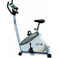
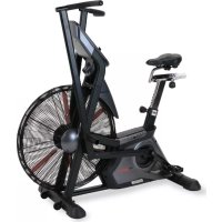
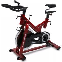
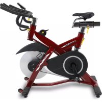
Mycron S220 - Indoor bike trainer BH FITNESS - Free user manual and instructions
Find the device manual for free Mycron S220 BH FITNESS in PDF.
User questions about Mycron S220 BH FITNESS
0 question about this device. Answer the ones you know or ask your own.
Ask a new question about this device
Download the instructions for your Indoor bike trainer in PDF format for free! Find your manual Mycron S220 - BH FITNESS and take your electronic device back in hand. On this page are published all the documents necessary for the use of your device. Mycron S220 by BH FITNESS.
USER MANUAL Mycron S220 BH FITNESS
natural_image
Line drawing of a stationary exercise bike with adjustable arms and wheels (no text or symbols)Instrucciones de montaje y utilización Instructions for assembly and use Instructions de montage et utilisation Montage und Gebrauchsanleitung Instruções de montagem e utilização Istruzioni di montaggio e uso Montage-en gebruiksinstrukties
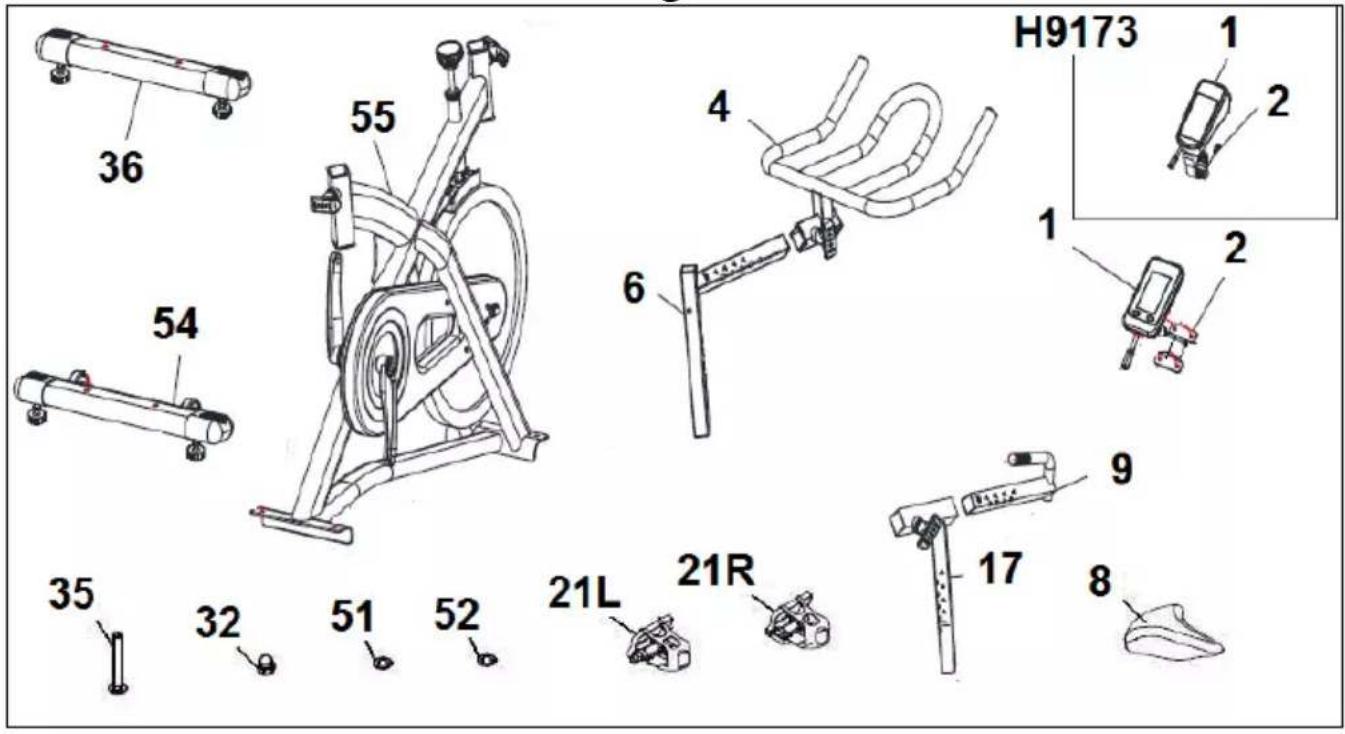
Fig.1
text_image
36 54 35 32 51 52 55 6 4 H9173 1 2 1 2 9 17 8Fig.2
text_image
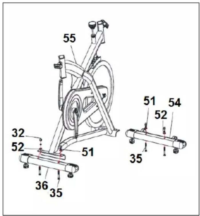
55 32 52 51 36 35 51 54 52 35Fig.3
text_image
4 6 18 55 A 6 18 55Fig.4
text_image
A 17 55 8 18 9 B 17 55 8 18Fig.5
text_image
H9173 2 4 1 2 3 4 66Fig.6
text_image
21L 57 56 21RFig.7
text_image
10Fig.8
natural_image
Line drawing of a stationary exercise bike with labeled components and measurement annotation (34), no text or symbols present.Fig.9
natural_image
Line drawing of a woman using an exercise bike with a 50-unit weight marker (no text or symbols on the diagram itself)Fig.10
text_image
19 48Fig.11
natural_image
Line drawing of an exercise bike with labeled components (no text or symbols beyond label)Español
This bicycle has been designed and constructed to provide maximum safety. Nevertheless, certain precautions should be taken when using exercise equipment. Read the whole manual before assembling and using the bicycle. It provides you with important information about assembly, safety and use of the machine. The following safety precautions should also be observed:
1 Keep children away from this equipment at all times. DO NOT leave them unsupervised in the room where this bicycle is kept.
2 It can only be used by one person at a time.
3 If you experience dizziness, nausea, chest pains or any other symptom while using this appliance STOP the exercise. SEEK MEDICAL ATTENTION IMMEDIATELY.
4 Use the appliance on a level, solid surface. DO NOT use the bicycle outdoors or close to water.
5 Keep your hands well away from any of the moving parts.
6 Wear clothing suitable for doing exercise. Do not use baggy clothing that might get caught up in the bicycle. Always wear running shoes or trainers when using the machine. Make sure all laces/cords are tied correctly.
7 This appliance must only be used for the purposes described in this manual. DO NOT use accessories that are not recommended by the manufacturer.
8 Do not place sharp objects near the machine.
9 Disabled people should not use the machine without the assistance of a qualified person or a doctor.
10 Do warm up stretching exercises before using the equipment.
11 Do not use the bicycle if it is not working correctly.
Caution: Consult your doctor before beginning to use the bicycle. This advice is especially important for those over 35 or suffering from health problems.
Keep these instructions safe for future use.
GENERAL INSTRUCTIONS.-
1 This unit has been designed for home use. The weight of the user must not exceed 115 kg.
2 Parents and/or those responsible for children should always take their curious nature into account and how this can often lead to hazardous situations and behaviour resulting in accidents.
Under no circumstances should this appliance be used as a toy.
3 The owner is responsible for ensuring that anyone who uses the machine is duly informed about the necessary precautions.
ASSEMBLY INSTRUCTIONS.-
The assistance of a second person is recommended when assembling this unit Take the unit out of its box and make sure that all of the pieces are there Fig.1:
(1) Monitor; (2) Bracket; (55) Main body; (4) Handlebar; (6) Handlebar stem; (17) Saddle post; (9) Horizontal saddle tube; (8) Saddle; (36) Rear stabiliser bar with adjustable feet; (54) Front stabiliser bar with wheels; (21L) Left pedal; (21R) Right pedal; (35) Slot head bolt M-10; (51) (52) Flat washer M10; (32) Cap nut M10.
-
Position the machine's rear stand on the rear stabilizer bar (36), as shown in Fig.2, insert the bolts (35), fit the flat washers (51) (52) and cap nuts (32) and then tighten securely.
-
Position the front stabiliser bar with wheels (54) with the wheels facing forwards, as shown in Fig.2, insert the bolts (35), fit the flat washers (51) (52) and cap nuts (32) and tighten securely.
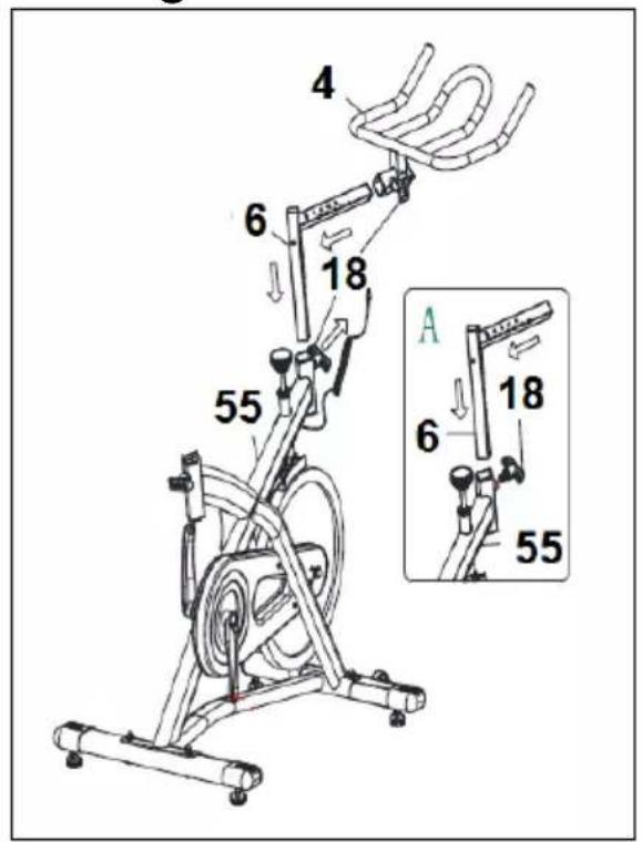
Position the handlebar (4) on the handlebar stem (6), Fig.3, tighten the knob (18) and then insert the handlebar stem (6) into the hole on the main body (55), Fig.3. Position it correctly and then tighten knob (18) by turning it clockwise.
ADJUSTING THE HANDLEBAR HORIZONTALLY.-
Position the handlebar (4) at a comfortable distance for doing exercise, now tighten knob (18) securely, Fig.3. Stay within the references.
ADJUSTING THE HANDLEBAR VERTICALLY.-
Position the handlebar (4) at a comfortable distance for doing exercise, now tighten knob (18) securely, Fig.3.
Stay within the references without going beyond the "STOP" mark.
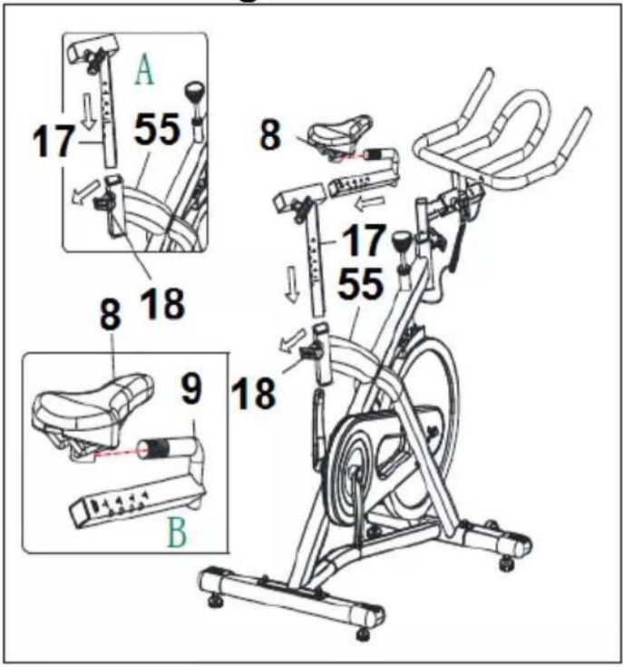
4.- ATTACHING THE SADDLE.-
Fit the saddle bracket (8), Fig.4, onto the horizontal saddle tube (9), as shown in Fig.4, fit the saddle into position and tighten the nuts on the bracket securely.
Next insert the horizontal saddle tube (9) through the hole on the saddle post (17), Fig.4, position it correctly and tighten the knob (18), Fig.4.
Insert the saddle post (17) into the boss on the main body (55), position it correctly and tighten the saddle post by using the adjustment knob (18), Fig.4, turning it clockwise.
ADJUSTING THE SADDLE HEIGHT.-
Loosen the saddle post adjustment knob (18) slightly by turning it anticlockwise, Fig.4, move the saddle to a position comfortable for doing exercise and then tighten the adjustment knob (18) securely by turning it clockwise.
Stay within the references without going beyond the "STOP" mark.
HORIZONTAL ADJUSTMENT OF THE SADDLE.-
Loosen the knob (18) slightly by turning it anticlockwise, Fig.4, move the saddle to a position comfortable for doing exercise and then tighten the knob (18) securely by turning it clockwise.
Stay within the references without going beyond the "STOP" mark.
5.- ATTACHING THE MONITOR.-
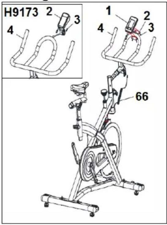
Fit the monitor (1), Fig.5, into the bracket (2) and insert the jack on the middle cable (66) into the back of the monitor (See the instruction book for the monitor).
The assembly instructions for the pedals must be followed to the letter, fitting these incorrectly could damage the screw thread on either the pedal or the crank.
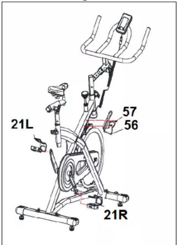
Right and left refer to the position that the user adopts when sitting on the saddle to do the exercises.
The right-hand pedal (21R), marked with the letter (R), screws onto the right-hand crank, also marked with an (R), in a clockwise direction. Tighten securely, Fig.6.
The left-hand pedal (21L), marked with the letter (L), screws onto the left-hand crank, also marked with an (L), in an anti-clockwise direction. Tighten securely, Fig.6.
7. FITTING THE BOTTLE HOLDER
Loosen off the two bolts (57) on the handlebar assembly (A) and position the bottle holder (56) then tighten up (Fig. 6).
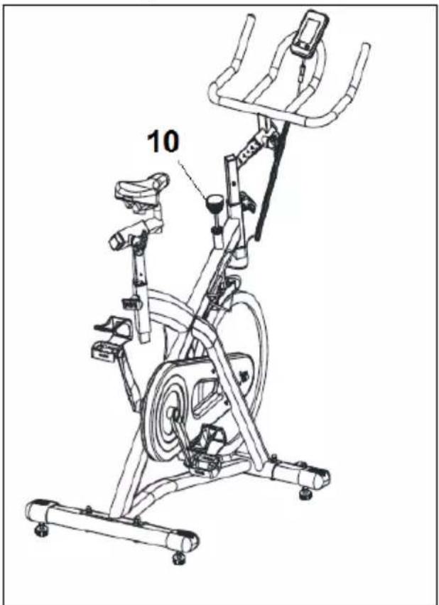
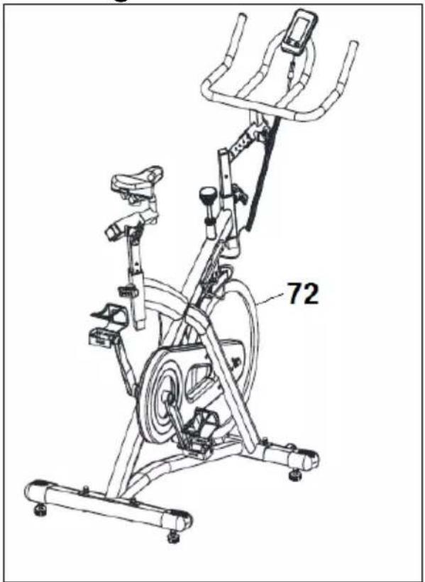
To provide an even level of exertion during exercise, this appliance is equipped with a tensioning control (10), located on the stem of the main body (55), Fig.7. This provides various exertion settings when turned clockwise.
To increase pedal resistance turn the tensioning control (10) clockwise (+) until the exertion level best suits your exercise requirements.
To reduce pedal resistance turn the tensioning control (10) anticlockwise (-). During exercise the flywheel will get hot due to the braking effect, so when you have finished exercising it is advisable to set the tensioning control (10) to minimum in order to help stop the brake shoe from hardening.
Important: This tensioning control (10) is equipped with an emergency braking system which, when applied with force (as shown by the arrow in Fig.7, produces a much sharper braking effect.
LEVELLING.-
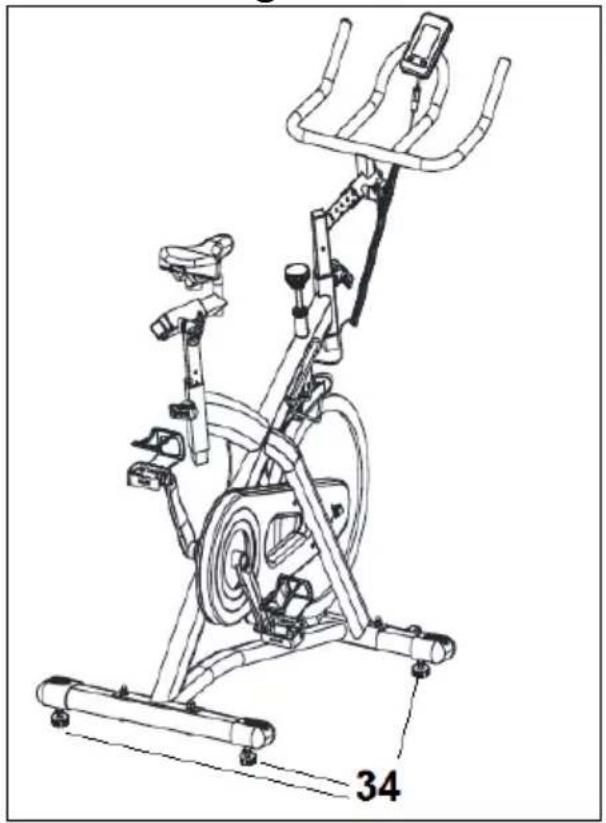
Once the unit has been placed into its final position, make sure that it sits flat on the floor and that it is level. This can be achieved by screwing the adjustable feet (34) up or down, as shown in Fig.8.
MOVEMENT & STORAGE.-
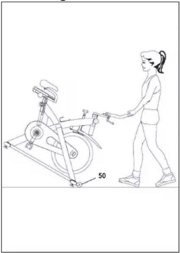
The unit is equipped with wheels (50) Fig.9, to make it easier to move. The wheels located at the front of your unit make it easier to move it into a chosen position, by lifting the rear of the unit up slightly and pushing it, as shown in Fig.9. Store your unit in a dry place, preferably not subject to changes in temperature.
MAINTAINING THE MACHINE.-
For health reasons it is necessary to clean the handlebars and seat after each class with a disinfectant spray, as well as removing any sweat from the bicycle's frame.
Apply anti-rust to the flywheel every time you clean the machine or at least once a month.
Apply oil in the contact surface of the flywheel with brake to avoid rattling noises. Fig.11.
Even though the pedals are already fitted, the right-hand pedal (marked R) screws on in a clockwise direction, whereas the left-hand pedal (marked L) does so in the opposite direction.
Maintenance:
-The tension of the pedal clip with the pedal should be checked weekly, using a 3mm allen key to adjust the set screw.
-Apply a little oil to the contact point of the pedal clip with the pedal to ensure that it locks on.
2. CHECKING THE TIGHTENING KNOBS.-
The 3 tightening knobs should be loosened off and sprayed with a lubricant to ensure that they remain operative.
- Check that the belt is tensioned properly. If the belt skids it will be necessary to tighten the belt.
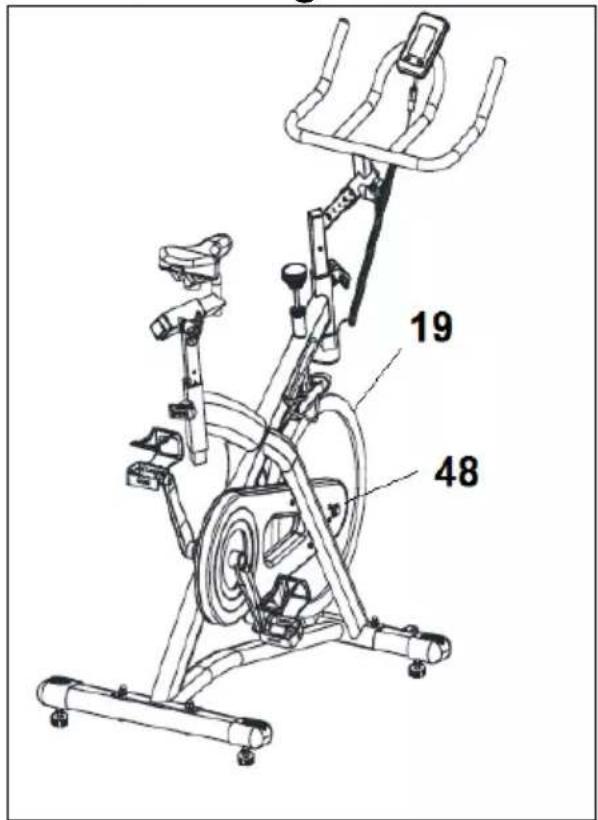
- Remove the side covers (19) (48) and loosen the nuts a maximum of two turns Fig.10.
-Tighten the small nuts with a spanner. Make sure that the nut rotates the same number of turns on both sides of the machine (generally 2 turns will be sufficient) otherwise the drive sprocket might become skewed, creating a lot more noise and making it possible for the belt to fall off.
-Tighten up nuts again and put the side covers (19) (48) back in their place.
-Whenever the tension setting on the machine is adjusted, readjust the brakes as well.
Do not hesitate to get touch with the Technical Assistance Service if you have any queries by phoning customer services (see last page in manual).
BH RESERVES THE RIGHT TO MODIFY THE SPECIFICATIONS OF ITS PRODUCTS WITHOUT PRIOR NOTICE.
Francais
IMPORTANTES CONSIGNES DE SÉCURITÉ.- PRÉCAUTIONS.
text_image
Technical diagram of a stationary exercise machine with labeled components and exploded viewTo order replacement parts: State the part code and Quantity
e-mail: info@bhfitness.pt
BH SERVICE PORTUGAL
Tel.: +351 234 729 510
e-mail: info@bhfitness.pt
BH GERMANY GmbH
Grasstrasse 13
45356 ESSEN
GERMANY
Tel: +49 2015 997018
e-mail:
technik@bhgermany.com
BH FITNESS NORTH AMERICA
20155 Ellipse
Foothill Ranch
CA 92610
Tel: + 1 949 206 0330
Toll free: +1 866 325 2339
service.uk@bhfitness.com
BH FITNESS ASIA
BH Asia Ltd.
No.80, Jhongshan Rd.,
Daya Dist.,
Taichung City 42841,
Taiwan. R.O.C.
Tel.: +886 4 25609200
Fax: +886 4 25609280
Block A, NO.68, Branch Lane
455, Lane 822,
Zhen Nan RD., Li Zi Yuan,
Putuo, Shanghai 200331, P.R.C.
Tel: +86-021-5284 6694
Fax:+86-021-5284 6814
e-mail: info@i-bh.cn
BH FITNESS FRANCE
SAV FRANCE
Tel : +33 0810 000 301
Fax : +33 0810 000 290
savfrance@bhfitness.com
BH SE RESERVA EL DERECHO A MODIFICAR LAS ESPECIFICACIONES DE SUS PRODUCTOS SIN PREVIO AVISO.
SPECIFICATIONS MAY BE CHANGED WITHOUT PRIOR NOTICE DUE TO OUR PROGRAMME OF CONTINUOUS PRODUCT DEVELOPMENT.
BH SE RÉSERVE LE DROIT DE MODIFIER LES SPECIFICATIONS DE SES PRODUITS SANS PRÉAVIS.