
Kickr Move - Fitness Equipment Wahoo - Free user manual and instructions
Find the device manual for free Kickr Move Wahoo in PDF.
| Product Type | Smart direct drive trainer |
| Dimensions (L x W x H) | 76.2 x 58.4 x 38.1 cm |
| Weight | 21.5 kg |
| Power supply | AC adapter (included), 100-240V |
| Max user weight | 113.5 kg |
| Training modes | Level, Resistance (0-100%), ERG (target power), SIM (road simulation) |
| Fore-aft movement | Yes, KICKR MOVE system |
| Axis feet | Adjustable damping (3 cap sizes) |
| Connectivity | Bluetooth, ANT+, Wi-Fi, Ethernet (via Direct Connect) |
| Bike compatibility | Quick release 130/135 mm, thru axle 12x142/148 mm |
| Cassette | Not included (use bike's cassette) |
| App compatibility | Wahoo Fitness app (iOS 15+, Android 11+), ELEMNT GPS, third-party platforms |
| Warranty | 1 year (parts and labor) |
| Maintenance and cleaning | Wipe with a dry cloth; do not use harsh chemicals |
| Safety | Use on a flat, stable surface; do not wear loose clothing; keep children and pets away |
| Spare parts and repairability | Contact Wahoo Fitness for any parts or repairs |
Frequently Asked Questions - Kickr Move Wahoo
User questions about Kickr Move Wahoo
0 question about this device. Answer the ones you know or ask your own.
Ask a new question about this device
Download the instructions for your Fitness Equipment in PDF format for free! Find your manual Kickr Move - Wahoo and take your electronic device back in hand. On this page are published all the documents necessary for the use of your device. Kickr Move by Wahoo.
USER MANUAL Kickr Move Wahoo
natural_image
Exterior view of a black Wahoo robotic device with 'KICKRA MOVE' branding (no additional text or symbols visible)WARNING Read this manual and all safety information thoroughly before assembly and use. Failure to follow the warnings and instructions could cause personal injury and/or physical damage to equipment or surroundings.
- Assemble the KICKR MOVE only as stated in the information contained in this manual.
- Do not modify the KICKR MOVE.
- All instructions can be viewed on our website: www.wahoofitness.com/instructions.
- Images may not reflect final product exactly.
The instructions below are classified according to the degree of danger or damage which may occur if the product is used incorrectly:
DANGER follow the instructions will result in death or serious injury.
INVENTING follow the instructions could result in death or serious injury.
CAUTION Failure to follow the instructions could cause personal injury and/or physical damage to equipment or surroundings.
KICKR MOVE Quick Start Guide
See full instructions for complete setup.
Scan the QR Code to get started with assembly and setup

WARNING
GENERAL SAFETY INFORMATION
- Improper or excessive exercise can result in serious injury. Always consult your physician before beginning or modifying any exercise program.
- Contact with the moving parts of the KICKR MOVE could result in serious injury.
- Do not put hands or objects near moving parts of the KICKR MOVE.
- Keep children and pets away from the KICKR MOVE.
- Do not wear loose clothing or shoes with loose laces that could result in unintended contact with moving parts.
- Do not exceed the maximum rider weight of 250 lbs (113.5 KG).
- Instability of the KICKR MOVE could result in serious injury. Only use the KICKR MOVE on stable, level surfaces.
- The KICKR MOVE is intended for indoor use only. Do not store outdoors or near water.
• The KICKR MOVE may become hot to the touch
when used for extended periods of time. Allow components to cool before touching.
- To avoid risk of fire or electric shock, only use the included power adapter with the KICKR MOVE.
- During your peak training season, keep the KICKR MOVE plugged in for automatic updates via Wi-Fi. Unplug your KICKR MOVE prior to cleaning and maintenance or if left unused for extended periods of time.
• Device alterations, improper and/or incomplete use, assembly or operation can result in serious injury. - Keep the KICKR MOVE in the locked position when not in use.
- If you use the KICKR CLIMB and KICKR MOVE together, you must use the KICKR CLIMB base adapter to avoid damage to the KICKR CLIMB while in use.
- To avoid damage to your bike or accessories, do not put anything under your front wheel, or attach your fork to any other climbing or steering accessory while using the KICKR MOVE.
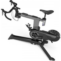
Thank you for purchasing the Wahoo KICKR MOVE!
LEARN MORE:
For more information or to submit a support request, visit www.wahoofitness.com/support
CONTACT US:
Wahoo Fitness
90 W. Wieuca Rd NE
Suite 110
Atlanta, GA 30342 United States
TELEPHONE:
United States: 1-877-978-1112
United Kingdom: +44-800-808-5773
US Phone Hours:
Monday - Friday
9 AM - 5 PM ET
UK Phone Hours:
Monday - Friday
2 PM - 10PM GMT
UNPACKING
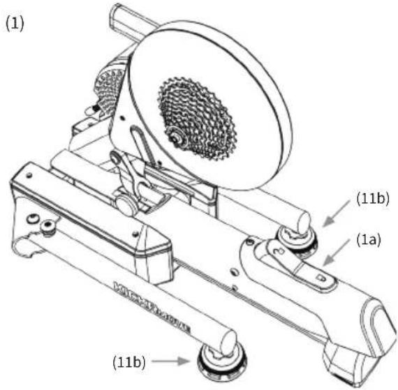
(1) KICKR MOVE
(1a) KICKR MOVE Lock Lever
(2) AC Power Adapter
(3) Quick Release Skewer
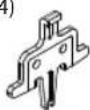
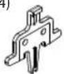
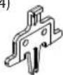
(4) Disc Brake Spacer
(5) 1.8mm Spacer
(6) Adapter A - For 130mm and 135mm Quick Release
(7) Adapter B - Reversible hub spacer for 130mm and 135mm Quick Release
(8) Adapter C - For 12x142 and 12x148 Thru Axle
(9) Adapter D - 12x142 Thru Axle
(10) Adapter E - 12x148 Thru Axle
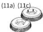
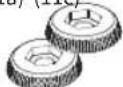
(11a) Axis Feet - Small
(11b) Axis Feet - Medium *Pre-installed
(11c) Axis Feet - Large
natural_image
Pure electrical circuit lines without any symbols
(4)

(5)

(6)* (7)* (8) (9) (10)


(11a) (11c)


* These items come preinstalled on the KICKR MOVE

PROTIP: Save all packaging and protective material for transportation and storage.
KICKR MOVE SETUP

Prior to setting up your KICKR MOVE, ensure the lock lever is securely locked to avoid risk of injury.
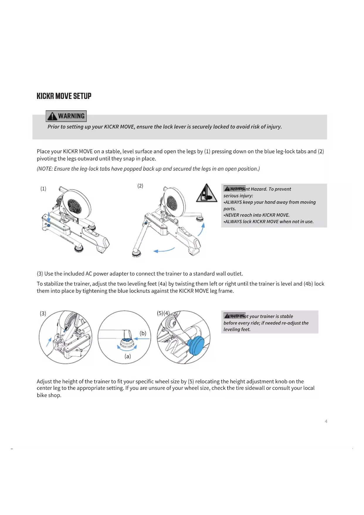
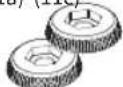
Place your KICKR MOVE on a stable, level surface and open the legs by (1) pressing down on the blue leg-lock tabs and (2) pivoting the legs outward until they snap in place.
(NOTE: Ensure the leg-lock tabs have popped back up and secured the legs in an open position.)

natural_image
Mechanical device with a textured circular component mounted on a base, labeled (1), showing no visible text or symbols.
natural_image
Mechanical device with rotating arm and gear assembly, showing motion arrows and a warning symbol (no text or labels)A iWARNPGint Hazard. To prevent
serious injury:
• ALWAYS keep your hand away from moving parts.
•NEVER reach into KICKR MOVE.
• ALWAYS lock KICKR MOVE when not in use.
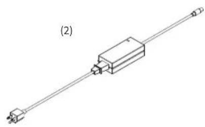
(3) Use the included AC power adapter to connect the trainer to a standard wall outlet.
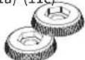
To stabilize the trainer, adjust the two leveling feet (4a) by twisting them left or right until the trainer is level and (4b) lock them into place by tightening the blue locknuts against the KICKR MOVE leg frame.

natural_image
Mechanical assembly diagram showing a clamping mechanism with no visible text or symbols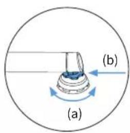
natural_image
Mechanical assembly diagram showing a blue component inserted into a gear mechanism (no text or labels)⚠️ Learn that your trainer is stable before every ride; if needed re-adjust the leveling feet.
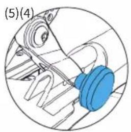
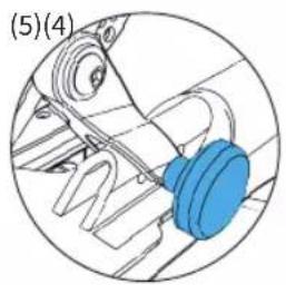
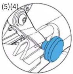
Adjust the height of the trainer to fit your specific wheel size by (5) relocating the height adjustment knob on the center leg to the appropriate setting. If you are unsure of your wheel size, check the tire sidewall or consult your local bike shop.
FOR 130MM OR 135MM QUICK RELEASE
Adapters Needed: A and B
KICKR MOVE comes pre-configured out of the box for bicycles with 130mm quick release spacing. If you have a bicycle with 130mm spacing proceed to "Attaching your Bicycle". For 135mm spacing, remove quick release skewer, reverse Adapter B and reinstall quick release skewer.

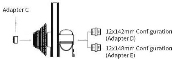
FOR 142MM OR 148MM THRU AXLE
Adapters Needed: C and D or E
To be used with the 12mm thru axle supplied with bicycle.
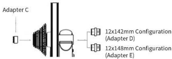
flowchart
graph LR
    A["Adapter C"] --> B["Component"]
    B --> C["Adapter D"]
    B --> D["Adapter E"]
    C --> E["12x142mm Configuration (Adapter D)"]
    D --> F["12x148mm Configuration (Adapter E)"]
ATTACHING YOUR BICYCLE
Brianhos attaching your bicycle, ensure the lock lever is securely locked to avoid risk of injury.
Shift your bicycle chain into the smallest sprocket in the front and rear, then remove your rear wheel. Install your bicycle on the KICKR MOVE by aligning the chain with the smallest sprocket on the KICKR MOVE and pressing down to fully seat the dropouts on the KICKR MOVE's axle.
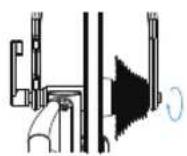
For bicycles with quick release - Secure your bicycle by tightening the quick release acorn nut and clamping the quick release lever shut. The quick release lever is "open" when it curves away from the bicycle frame (1); the lever is "closed" when it curves towards the bicycle frame (2). The handle of the quick release skewer is always on the non-drive (non cassette) side of the KICKR MOVE. Only use the provided quick release skewer while using the KICKR MOVE.
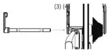
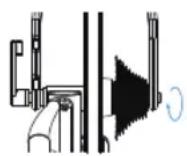
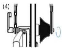
For bicycles with thru axle - Secure your bicycle by reinstalling your bicycle's thru axle (3) and tightening to manufacturer specifications (4).
natural_image
Technical line drawing of a mechanical assembly with no visible text or symbols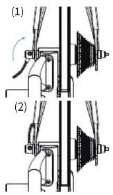
To properly tighten the quick release skewer or thru axle may result in property damage, including damage to the attached bicycle, or personal injury. If you are unsure of the proper tension, please consult your local bike shop or contact Wahoo Fitness for assistance.
Do NOT ride the KICKR MOVE until the quick release skewer or thru axle is properly tightened.

PROTIP: Lift the front wheel up while pressing down on the saddle to ensure the bicycle is fully seated on the trainer.
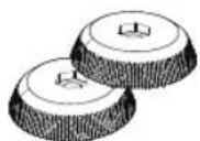
AXIS FEET ADJUSTMENT
KICKR MOVE's integrated AXIS feet let cyclists of all types customize ride feel to match their unique riding style, enhance feedback and offer a more realistic training experience.
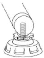
Step 1: Unthread "outrigger" feet
Step 2: Remove top cap (part between blue locknut and base of the foot)
Step 3: Install desired top cap
0-140 lbs (0 - 63 kg) Use smallest diameter cap
141-180 lbs (63 - 81 kg) Use middle cap (installed by default)
181 lbs + (81kg +) Use largest diameter cap
WARNING
WARNING: Failure to select the appropriate top cap for your weight may result in property damage or personal injury. Do NOT ride the KICKR MOVE until the appropriate top cap is installed.
COMPLETE YOUR SETUP USING THE WAHOO FITNESS APP
Download the Wahoo App for free from the Apple App Store or Android Google Play Store. Use this app to complete your device registration, complete your profile, perform necessary firmware updates, and pair your sensors.
START A WORKOUT: From the workout screen select the green "start" button to begin the workout. Swipe right to view the KICKR MOVE page. This page enables you to view your workout and control the KICKR MOVE.
KICKR MOVE WORKOUT MODES:
The Wahoo Fitness App has the following workout modes that you can use to control your KICKR MOVE:
LEVEL: Just like riding on a fluid or wind trainer, the faster you go, the harder it gets. The level you select determines the progression of your power curve.
RESISTANCE: This allows you to set the resistance of the brake anywhere from 0 to 100%. Regardless of speed, the brake will remain set until you decide to change it.
ERG: Set your desired power, the KICKR MOVE will increase or decrease the resistance to maintain a constant power output, regardless of speed.
SIM: Enter your weight, bike type, riding position, headwind, and grade and the KICKR MOVE will accurately model the power curve just as if you were riding outdoors.
COMPATIBILITY
• ELEMNT GPS Bike Computers.
- Apple Devices running iOS 15 or newer.
- Android devices with Android 11 or newer.
- Windows or MacOS computer with Bluetooth, ANT+, a Wi-Fi network or Direct Connect Ethernet accessory.
LIMITED WARRANTY
Wahoo Fitness warrants this product to be free from defects in material and workmanship, under normal use, for one year from the date of original purchase. Defects that have resulted from improper or unreasonable use or maintenance, accidents, excess moisture, insects, improper packaging, lightning, power surges, or unauthorized tampering, alteration, or modification will not be covered. Wahoo Fitness will, at its discretion, repair or replace with a comparable product, at no charge to the customer for parts or labor, so long as customer is responsible for shipping costs. Products may be new, refurbished, or reconditioned and are warranted for the unexpired period of the original purchase or 60 days from the return, whichever is greater. Any products replaced become the property of Wahoo Fitness.
WHERE PERMITTED, THE PROVISIONS OF THIS LIMITED WARRANTY ARE IN LIEU OF ANY OTHER WRITTEN WARRANTY, WHETHER EXPRESSED OR IMPLIED, WRITTEN OR ORAL, INCLUDING ANY WARRANTY OF MERCHANTABILITY OR FITNESS FOR A PARTICULAR PURPOSE. IN NO EVENT SHALL WAHOO FITNESS BE LIABLE FOR SPECIAL, INCIDENTAL, CONSEQUENTIAL, OR INDIRECT DAMAGES. SOME PLACES DO NOT ALLOW LIMITATIONS ON THE EXCLUSION OR LIMITATION OF LIABILITY TO SPECIFIED AMOUNTS SO THE ABOVE LIMITATIONS OR EXCLUSIONS MAY NOT APPLY TO YOU.
To obtain warranty services, contact Wahoo Fitness for shipping instructions and an RMA tracking number. Return your device, freight prepaid, along with the original sales receipt which is a required proof of purchase for warranty repairs, with the RPM tracking number written on the outside of the package, and mail it to Wahoo Fitness.
WFBKTR123
FCC: PAD147
IC: 10563A-WF147
AUSTRALIAN WARRANTY INFORMATION
This document details the terms and conditions of the warranty provided with this product. Please disregard any other representations contained on this product's packaging or provided with this product, which constitute or appear to constitute a warranty. Subject to the exclusions and limitations set out below, we warrant to you that if you purchase a product directly from us, or from any of our authorised resellers, that it will not contain defects which are a result of faulty manufacturer workmanship or materials. This warranty subsists for 1 year from the date of purchase.
Subject to any rights you have under the Australian Consumer Law, we will not be liable for defects which are a result of damage or loss caused by factors beyond our control, any product which has not been maintained according to any care or maintenance instructions provided with the product, any alterations to a product which are not performed by us, or damage or defects caused to the product due to unusual or non-recommended use. We will not be liable for any special, indirect, consequential or economic loss or damage or loss of profits whatsoever suffered by you or any other person resulting from any act or omission by us.
Our total liability in respect of this Warranty against Defects is limited to the replacement of the goods.
Any claim made under this warranty must be made by returning the defective goods to us, at your expense. Please provide details of the defect and evidence of purchase to support@wahoofitness.com
This Warranty against Defects is provided in addition to other rights and remedies that you may have at law. Our goods come with guarantees that cannot be excluded under the Australian Consumer Law. You are entitled to a replacement or refund for a major failure and for compensation for any reasonably foreseen loss or damage. You are also entitled to have the goods repaired or replaced if the goods fail to be acceptable quality and the failure does not amount to a major failure.
Consult the dealer or an experienced radio/TV technician for help.
To assure continued compliance, any changes or modifications not expressly approved by the party responsible for compliance could void the user's authority to operate this equipment. (Example- use only shielded interface cables when connecting to a computer or peripheral devices).
Caution! The manufacturer is not responsible for any radio or TV interference caused by unauthorized modifications to this equipment. Such modifications could void the user's authority to operate the equipment.
IC STATEMENT
This device complies with Industry Canada license-exempt RSS standard(s). Operation is subject to the following two conditions: (1) this device may not cause interference, and )2_ this device must accept any interference, including the interference that may cause undesired operation for the device. The device meets the exemption from the routine evaluation limits in section 2.4 of RSS 102 and users can obtain Canadian information on RF exposure and compliance.
CE STATEMENT
Hereby, Wahoo Fitness declares that this product is in compliance with:
The essential requirements and essential relevant provisions of directive 2014/53/EU
The full text of EU declaration of conformity (DoC) is available at the following internet address: www.wahoofitness.com/regulatory-notices. The object of the declaration described above is in conformity with the relevant European Union harmonization Legislation: Directive 2014/53/EU and any other applicable directives.
This declaration is issued under the sole responsibility of Wahoo Fitness, LLC.
All listed Wahoo products operate within the 2402-2480MHz frequency band and below the maximum output power threshold of 100mW (20dBm).
Regulatory authorities within the EU may obtain compliance information by writing to:
Wahoo Fitness LLC
90 W. Wieuca Road 110
Atlanta, GA 30342
Before beginning or modifying any exercise program, please consult your physician. If you have a pacemaker or other implanted electronic device, consult your physician before using a heart rate sensor. This product is intended for recreational use only and is not intended for medical purposes. Heart rate and other readings could be influenced by interference from external sources. If you use this product with navigation software, always be aware of your surroundings and do not fixate on the screen. Moreover, set destinations and other user inputs prior to your departure to ensure your attention stays on task and your facilities are directed to your activity and not the device. The device contains no user user serviceable parts and repairs / modifications should only be made by a technician authorized by Wahoo Fitness. Any unauthorized modifications or repairs will void your warranty. Do not leave devices exposed to excessive heat or cold.
CALIFORNIA PROPOSITION 65
The enclosed hardware and its packaging contain chemicals the State of California has found to cause cancer, birth defects or reproductive harm.
FCC RULES PART 15
The enclosed hardware device complies with part 15 of the FCC Rules. Operation is subject to the following two conditions: (1) This device may not cause harmful interference and (2) it must accept any interference received, including interference that may cause undesired operation.
FCC COMPLIANCE STATEMENT:
This equipment has been tested and found to comply with limits for a Class B digital device, pursuant to Part 15 of the FCC rules. These limits are designed to provide reasonable protection against harmful interference in residential installations. The equipment generates, uses, and can radiate radio frequency energy, and if not installed and used in accordance with the instructions, may cause harmful interference to radio communications. However, there is no guarantee that interference will occur in a particular installation.
If this equipment does cause interference to radio or television equipment reception, which can be determined by turning the equipment off and on, the user in encouraged to try to correct the interference by one or more of the following measures:
-Reorient or relocate the receiving antenna
Atlanta, GA 30342 United States
TELÉFONO:
natural_image
Technical line drawing of a mechanical component with a shaft and housing (no text or symbols)
(4)

(5)

(6)* (7)* (8) (9) (10)


(11a) (11c)

natural_image
Mechanical device with a textured circular component mounted on a base, showing no visible text or symbols.
natural_image
Mechanical device with rotating arm and gear assembly, showing motion arrows and a warning symbol (no text or labels)APPERFENG
natural_image
Mechanical assembly diagram showing a bracket with internal components and directional arrows (no text or labels)

natural_image
Mechanical assembly diagram showing a blue component inserted into a gear mechanism (no text or labels)ADVERTENCIA
Adapters Needed: A and B
PARA EJES DE 142 MM O 148 MM
Adapters Needed: C and D or E
natural_image
Technical line drawing of a mechanical assembly with no visible text or symbols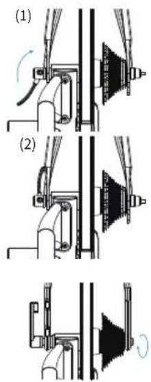
Atlanta, GA 30342 United States
TÉLÉPHONE:
natural_image
Pure electrical circuit lines without any symbols


(6)* (7)* (8) (9) (10)


natural_image
Mechanical device with a textured circular component mounted on a base, labeled (1), showing no visible text or symbols.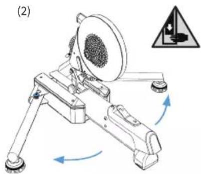
natural_image
Mechanical device with rotating arm and textured circular component, no visible text or symbolsnatural_image
Mechanical assembly diagram showing a lever mechanism with no visible text or symbols

natural_image
Mechanical assembly diagram showing a blue component inserted into a gear mechanism (no text or labels)Adapters Needed: A and B
POUR UN AXE TRAVERSANT DE 142 MM OU 148 MM
Adapters Needed: C and D or E
ATTACHER VOTRE VÉLO
natural_image
Technical line drawing of a mechanical assembly with no visible text or symbols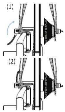
Atlanta, GA 30342 United States
TELEFONO:
natural_image
Technical line drawing of a mechanical component with a shaft and housing (no text or symbols)
(4)

(5)

(6)* (7)* (8) (9) (10)


(11a) (11c)

natural_image
Mechanical device with a textured circular component mounted on a base, labeled (1), showing no visible text or symbols.
natural_image
Mechanical device with rotating arm and gear assembly, showing motion arrows and a warning symbol (no text or labels)natural_image
Mechanical assembly diagram showing a bracket with internal components and directional arrows (no text or labels)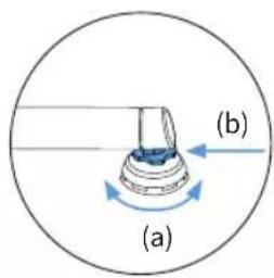
natural_image
Mechanical assembly diagram showing a blue component inserted into a gear mechanism (no text or labels)Adapters Needed: A and B
PER ASSE PASSANTE DA 142 MM O 148 MM
Adapters Needed: C and D or E
natural_image
Technical line drawing of a mechanical assembly with no visible text or symbols
Atlanta, GA 30342 United States
전화
미국:1-877-978-1112
전화 가능 시간:월-금 오전
9시\~오후5시 동부시간대
natural_image
Technical line drawing of a mechanical component with a shaft and housing (no text or symbols)
(4)

(5)

(6)* (7)* (8) (9) (10)


(11a) (11c)

natural_image
Mechanical device with a textured circular component mounted on a base, showing no visible text or symbols.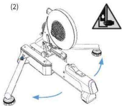
natural_image
Mechanical device with rotating arm and gear assembly, showing motion arrows (no text or symbols)natural_image
Mechanical assembly diagram showing a bracket with arrows indicating motion (no text or symbols)

natural_image
Mechanical assembly diagram showing a blue component inserted into a gear mechanism (no text or labels)natural_image
Technical line drawing of a mechanical assembly with no visible text or symbols

Atlanta, GA 30342 United States
TELEFON:
USA: 1-877-978-1112
Bürozeiten:
natural_image
Technical line drawing of a mechanical component with a shaft and housing (no text or symbols)
(4)

(5)

(6)* (7)* (8) (9) (10)


(11a) (11c)
natural_image
Mechanical device with a circular component and rotating shaft, labeled (1), showing no text or symbols on the device itself.
natural_image
Mechanical device with rotating arm and gear assembly, showing motion arrows and a warning symbol (no text or labels)
WARNUNG
natural_image
Mechanical assembly diagram showing a robotic arm with motion arrows and no visible text or symbols

natural_image
Mechanical assembly diagram showing a blue component inserted into a gear mechanism (no text or labels)
WARNUNG
Adapters Needed: A and B
135mm Configuration (Adapter B)
FÜR 142 MM ODER 148 MM STECKACHSE
Adapters Needed: C and D or E
natural_image
Technical line drawing of a mechanical assembly with two views (no text or symbols)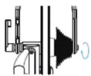
Atlanta, GA 30342 United States
电话:
美国: 1-877-978-1112
电话服务时间:
natural_image
Pure electrical circuit lines without any symbols
(4)
(5)

(6)* (7)* (8) (9) (10)


(11a) (11c)

natural_image
Mechanical device with a circular component and directional arrow, labeled (1), showing no readable text or symbols.
natural_image
Mechanical device with rotating arm and circular component, no visible text or symbols警告 夹点危险。为防止严重伤害:
natural_image
Mechanical assembly diagram showing a lever mechanism with arrows indicating motion (no text or labels)
natural_image
Mechanical assembly diagram showing a blue component inserted into a gear mechanism (no text or labels)Adapters Needed: A and B
针对142MM或148MM贯通轴
Adapters Needed: C and D or E
可配用适于自行车的12mm贯通轴。
flowchart
graph LR
    A["Adapter C"] --> B["Component"]
    B --> C["Adapter D"]
    B --> D["Adapter E"]
    C --> E["12x142mm Configuration (Adapter D)"]
    D --> F["12x148mm Configuration (Adapter E)"]
连接您的自行车(安装到自行车上)
natural_image
Technical line drawing of a mechanical assembly with no visible text or symbols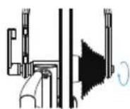
Atlanta, GA 30342 United States
電話:
美國: 1-877-978-1112
電話服務時間:
natural_image
Pure electrical circuit lines without any symbols
(4)
(5)

(6)* (7)* (8) (9) (10)


(11a) (11c)
natural_image
Mechanical device with a textured circular component mounted on a base, showing no visible text or symbols.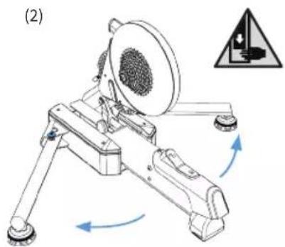
natural_image
Mechanical device with rotating arm and gear assembly, showing motion arrows (no text or symbols)natural_image
Mechanical assembly diagram showing a clamping mechanism with no visible text or symbols

natural_image
Mechanical assembly diagram showing a blue component inserted into a gear mechanism (no text or labels)針對142MM或148MM貫通軸
所需轉換座: C and D or E
相容於使用的自行車上的12mm貫通軸。

連接您的自行車
natural_image
Technical line drawing of a mechanical assembly with no visible text or symbols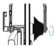
Atlanta, GA 30342 United States
電話:
natural_image
Technical line drawing of a mechanical component with a shaft and housing (no text or symbols)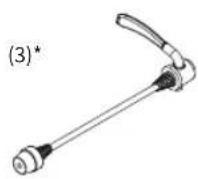
(4)
(5)

(6)* (7)* (8) (9) (10)


(11a) (11c)

natural_image
Mechanical device with a circular component mounted on a base, showing internal structure and mounting points (no text or symbols visible)
natural_image
Mechanical device with rotating arm and gear assembly, showing motion arrows and a warning symbol (no text or labels)natural_image
Mechanical assembly diagram showing a lever mechanism with no visible text or symbols

natural_image
Mechanical assembly diagram showing a blue component inserted into a housing (no text or labels)Adapters Needed: A and B
Adapters Needed: C and D or E
natural_image
Technical line drawing of a mechanical assembly with no visible text or symbols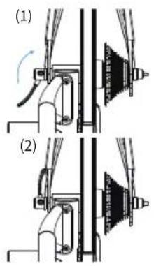
Atlanta, GA 30342 United States
TELEFON:
natural_image
Technical line drawing of a mechanical component with a shaft and housing (no text or symbols)
(4)

(5)

(6)* (7)* (8) (9) (10)


(11a) (11c)

natural_image
Mechanical device with a circular component mounted on a base, showing internal components and a blue arrow indicating direction (no text or symbols)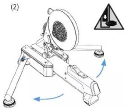
natural_image
Mechanical device with rotating arm and gear assembly, showing motion arrows and a warning symbol (no text or labels)
OSTRZEZENIE
natural_image
Mechanical assembly diagram showing a bracket with arrows indicating motion direction (no text or symbols)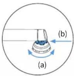

natural_image
Mechanical assembly diagram showing a blue component inserted into a gear mechanism (no text or labels)
0STBZE7BNUE
dą jazdq sprawdź,
DO 142 MM LUB 148 MM PRZEZ OŚ
MOCOWANIE ROWERU
natural_image
Technical line drawing of a mechanical assembly with no visible text or symbols


- KICKR MOVE Quick Start Guide
- See full instructions for complete setup.
- WARNING
- GENERAL SAFETY INFORMATION
- Thank you for purchasing the Wahoo KICKR MOVE!
- LEARN MORE:
- CONTACT US:
- TELEPHONE:
- US Phone Hours:
- UK Phone Hours:
- UNPACKING
- KICKR MOVE SETUP
- FOR 130MM OR 135MM QUICK RELEASE
- FOR 142MM OR 148MM THRU AXLE
- ATTACHING YOUR BICYCLE
- AXIS FEET ADJUSTMENT
- COMPLETE YOUR SETUP USING THE WAHOO FITNESS APP
- KICKR MOVE WORKOUT MODES:
- COMPATIBILITY
- LIMITED WARRANTY
- AUSTRALIAN WARRANTY INFORMATION
- IC STATEMENT
- CE STATEMENT
- CALIFORNIA PROPOSITION 65
- FCC RULES PART 15
- FCC COMPLIANCE STATEMENT:
- TELÉFONO:
- APPERFENG
- ADVERTENCIA
- PARA EJES DE 142 MM O 148 MM
- TÉLÉPHONE:
- POUR UN AXE TRAVERSANT DE 142 MM OU 148 MM
- ATTACHER VOTRE VÉLO
- TELEFONO:
- PER ASSE PASSANTE DA 142 MM O 148 MM
- 전화
- WARNUNG
- FÜR 142 MM ODER 148 MM STECKACHSE
- 针对142MM或148MM贯通轴
- 连接您的自行车(安装到自行车上)
- 電話:
- 針對142MM或148MM貫通軸
- 連接您的自行車
- OSTRZEZENIE
- 0STBZE7BNUE
- DO 142 MM LUB 148 MM PRZEZ OŚ
- MOCOWANIE ROWERU
Brand : Wahoo
Model : Kickr Move
Category : Fitness Equipment