FX-MS125 - Lawn mower Fuxtec - Free user manual and instructions
Find the device manual for free FX-MS125 Fuxtec in PDF.
User questions about FX-MS125 Fuxtec
0 question about this device. Answer the ones you know or ask your own.
Ask a new question about this device
Download the instructions for your Lawn mower in PDF format for free! Find your manual FX-MS125 - Fuxtec and take your electronic device back in hand. On this page are published all the documents necessary for the use of your device. FX-MS125 by Fuxtec.
USER MANUAL FX-MS125 Fuxtec
natural_image
Technical line drawing of a mechanical assembly with no visible text or symbolsnatural_image
Black and white photo of a Fuxtecv feed pump with attached sensor and clamp (no visible text or symbols)text_image
Illustration showing five different safety gear and device installation steps, labeled (1), with illustrations of workers in protective gear.natural_image
Close-up of a person holding a mechanical device with coiled cables, against a black background (no visible text or symbols)natural_image
Technical illustration of mechanical components including crimping rods, a motor, and a cylindrical housing (no text or symbols)Installation des Schutzschildes
natural_image
Technical line drawings of a mechanical component assembly (no text or symbols)Montage des Metallblatts
text_image
Technical diagram of a mechanical assembly with numbered parts, likely a valve or pump component.Schritte:
natural_image
Line drawing of hands using a tool to adjust or install a mechanical component (no text or symbols present)natural_image
Diagram of a mechanical device with attached lever and directional arrows, no text or symbols presentnatural_image
Technical line drawing of a mechanical device with a downward arrow indicator (no text or symbols present)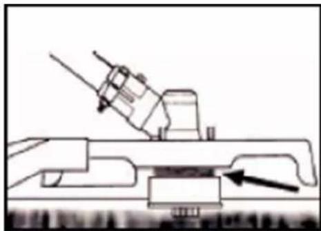
natural_image
Technical line drawing of a mechanical assembly with an arrow indicating a component (no text or symbols present)natural_image
Diagram of a mechanical device emitting smoke or vapor, with arrows indicating direction (no text or symbols)TRIMMEN UM BÄUME
natural_image
Technical line drawing of a mechanical assembly with no visible text or symbolsWartung Zündkerze
text_image
0.6~0.7mmnatural_image
Close-up of a mechanical component with labeled parts F and E, showing internal components and a ruler (no text or symbols beyond labels)natural_image
Mechanical device with attached lever and sensor components, no visible text or symbolsYour new device has been developed and designed to meet FUXTEC's high standards, such as easy operation and user safety. Properly treated, this device will serve you well for years to come.

WARNING: To reduce the risk of injury, the user must read and understand this manual before operating the device.
FUXTEC GMBH
CAPPING ROAD 69, 71083 HERRENBERG, GERMANY
TABLE OF CONTENTS
-
TECHNICAL DATA 39
-
SYMBOLS AND SAFETY INSTRUCTIONS ON THE DEVICE.... 40
-
INTENDED USE AND GENERAL SAFETY INSTRUCTIONS .... 43
-
HINTS FOR ACCESSORIES.... 45
-
NOTES ON WORKING WITH THE METAL BLADE 46
-
PUTTING ON THE SHOULDER HARNESS 48
-
COMPONENT OVERVIEW.... 49
-
MOUNTING THE DEVICE 50
-
COLD STARTING THE ENGINE.... 55
-
WARM START OF THE ENGINE.... 57
-
STOPPING THE DEVICE 57
-
TRIMMING TECHNIQUES.... 57
-
REPLACING NYLON THREAD.... 59
-
MAINTENANCE SCHEDULE.... 61
-
STORAGE OF THE DEVICE....63
-
TROUBLESHOOTING.... 64
CUSTOMER SERVICE 65
- WARRANTY 66
• DISPOSAL NOTE...... 66
37. EC DECLARATION OF CONFORMITY 67
We are continually striving to improve our products. Therefore technical data and illustrations may change!
21. Technical Data
| Type | FX-MS125 |
| Engine | air-cooled; 2-stroke |
| Cubic capacity | 51.7cm^3 |
| Maximum output power (kW)(conformity with ISO 8893) | 2.2kW / 7,500min^-1 |
| Maximum speed of the engine | 9,000 min^-1 |
| Idle speed of the engine | 3,000 min^-1 |
| Maximum speed of the spindle(tooth blade) | 7,100 min^-1 |
| Maximum speed of the spindle(thread spool) | 6,600 min^-1 |
| L_PA at the operator's position | 99.5dB(A) (K=3dB) |
| Measured L_WA according to ISO 10884 | 107.7dB(A) (K=3dB) |
| Guaranteed L_WA | 113dB(A) |
| Maximum vibration values at each handle | 5.259m/s^2 k=1.5m/s^2 |
| Maximum thread diameter | 3.0mm |
| Diameter of the metal blade | 305mmx1.6mm-2T / 255mmx1.6mm-3T/ 255mmx1.6mm-4T/ 255mmx1.6mm-8T |
| Rotation direction of the cutting device | Counterclockwise (see the mark on the plate) |
| Number of handles | 2 pieces |
| Dry weight (without fuel, cutting assembly, carrying strap) | 5.5kg |
| Fuel tank capacity (L) | 1.2 |
| Fuel consumption (kg/h) (in accordance with ISO 8893) | 0.98 kg |
| Specific fuel consumption(g/kWh) (in accordance with ISO 8893) | 630 g |
22. Symbols and safety instructions on the device
 | WARNING! IMPROPER OPERATION MAYLEAD TO SERIOUS INJURY |
 | READ AND UNDERSTAND THIS USER MANUAL BEFORE USE. |
 | WEAR EYE PROTECTION, EAR PROTECTION, AND HEAD PROTECTION |
 | WEAR FOOT PROTECTION. |
 | WEAR GLOVES (sharp edges!). |
 | DO NOT TOUCH THE ROTATING BLADE,DANGER OF INJURY |
 | ALWAYS KEEP 15 METERS AWAY FROMOTHER PEOPLE |
 | THE GUARANTEED NOISE LEVEL COMPLIES WITH THELEGAL NOISE GUIDELINES |


NO SMOKING AND OPEN FLAMES NEAR THE DEVICE

WARNING: DANGER OF HOT COMPONENTS

ALWAYS SWITCH OFF THE DEVICE AND ENSURE THAT THE CUTTING TOOL IS STOPPED BEFORE CLEANING, REMOVING OR ADJUSTING IT.

WARNING: EXHAUST GASES OF THIS PRODUCT CONTAIN CHEMICALS THAT CAUSE CANCER, BIRTH DEFECTS AND OTHERS
WARNING! NEVER CHANGE THE ENGINE. IMPROPER USE OF THE DEVICE CAN CAUSE SERIOUS OR FATAL PERSONAL INJURY.

MAXIMUM NUMBER OF ROTATION OF THE SPINDLE (LAWN TRIMMER): 6600 min ^-1

MAXIMUM SPEED OF THE SPINDLE (MOTOR SCYTHE): 7100 min ^1
Do not allow others to use this Device unless they have been fully instructed and have read and understood the user manual.

Prolonged use of the device exposes the user to shocks that can lead to white finger disease (Raynaud's syndrome) or carpal tunnel syndrome. This condition reduces the hand's ability to sense and regulate temperature,
causes numbness and heat sensations, and can lead to nerve and circulatory damage and tissue death.
Not all factors leading to white finger disease are known. Still, cold weather, smoking, and other conditions affecting the blood vessels and blood circulation, as well as extensive or prolonged exposure to shocks, are mentioned as factors in the development of white finger disease. To reduce the risk of white finger disease and carpal tunnel syndrome, please note the following
- Wear gloves and keep your hands warm.
• Take regular breaks.
All the above precautions cannot eliminate the risk of white finger disease or carpal tunnel syndrome. Long-term and regular users are, therefore, advised to monitor the condition of their hands and fingers closely. Consult a doctor immediately if any of the above symptoms occur.

The operating noise of the tool may damage your hearing. Wear a sound-proofing (Oropax or ear muffs) to protect it. Long-term and regular users are recommended to check their hearing regularly. Be especially vigilant and careful when wearing hearing protection, as it limits your ability to hear warnings (cries, alarms, etc.).

WARNING: Some noise exposure from this device is unavoidable. Do not work in noisy environments during approved and designated times. If necessary, observe rest periods and limit the duration of work to the minimum required. Wear suitable hearing protection for your personal protection and the protection of persons in the vicinity.
23. Intended use and general safety instructions
This device may only mow grass, weeds, and undergrowth. Never use it for other purposes, as this can cause serious injuries!
Correct safety instructions must be followed. DO NOT EXPOSE YOURSELF OR OTHERS TO DANGER. Follow these general safety instructions:
- Always wear safety glasses for eye protection. Long hair must be tied back. Do not wear loose clothing or jewellery that can get caught in the device's moving parts. Always wear safe, non-slip and robust safety shoes. Legs and feet are recommended to be fully protected to guard against flying objects during operation.
-
Check the device for loose parts (nuts, bolts, screws, etc.). Service or replace them if necessary before using the device. Do not use accessories with this drive head other than those recommended by the manufacturer. Otherwise, severe injury to the user or bystanders and damage to the device may result.
-
Keep the handles free of oil and fuel.
- Always use the handles and shoulder strap when cutting.
- Do not smoke when mixing the fuel or filling the tank
- Do not mix fuel in an enclosed space or near open fires. Ensure adequate ventilation/aeration.
- Mix and store the fuel mixture in a marked container approved for such use according to local regulations
- Never remove the fuel filler cap while the engine is running.
- Do not operate the device in enclosed spaces or buildings. Exhaust gases contain dangerous carbon monoxide.
- Do not attempt to adjust the device while running or carrying it. Always fix the device on a flat, free surface.
- Do not use the device if it is damaged. Never remove any protective devices from the device. That can cause serious injury to the operator or bystanders and further damage the device.
- Check the area to be cut and remove any objects entangled in the nylon cutting head or blade. Also, remove any objects that the device may throw around while cutting.
- Never leave the device unattended.
- Do not stretch out far forward. Always maintain a firm stand and balance. Never let the device run while standing on a ladder or any other unstable standing position.
- Children must not have access to the device. Spectators should stand at least 15 meters away from the working area.
- Keep hands and feet away from the nylon cutting head or metal blade during operation.
- Do not use the device if you are tired, ill, or under the influence of medication, drugs, or alcohol.
- Use an undamaged nylon cutting head. Stop the device and check the nylon cutting head if you hit a stone or any other obstacle. Never use a defective or unbalanced nylon cutting head.
- Before starting, after failure or impact, always check the device and make sure it is in good condition.
- Attention! Local regulations may limit the use of the device
- Always keep the device with the cutting tool in good condition. Note improper maintenance, the use of non-compliant spare parts, or the removal or modification of safety devices can cause damage to the device and severe injury to the person working with it.
- Secure the device well during transport to prevent fuel loss, damage to the device, and injury. Always fit the transport protection of the cutting blade before transporting or stowing the device.
- On devices with a clutch, check that the cutting attachment stops rotating when the engine is idling.
- Always check the device for loose fasteners, fuel leaks, damaged parts, etc., before each use. Replace used parts before use.
- It is necessary to take sufficient breaks and change the working position.
- Do not store the device in a closed area where fuel vapours can reach an open fire from water heaters, stoves, etc. Store the device in a well-ventilated area only.
- IMPORTANT: When filling the fuel, ensure the engine is off and cooled down. Never refuel when the device is running or hot.
24. Hints for accessories
- Make sure that your product is only equipped with original accessories. Only use the original parts that the manufacturer specifies. The use of any other accessories or attachments may cause injury to the user and damage to the device.
- Clean the device thoroughly, especially the fuel tank and air filter. After using the device, remove all fuel.
- If you approach a user of the device as a spectator, carefully attract his attention and confirm that the user will stop the device. Please do not startle or distract the user. Otherwise, you could cause an unsafe situation.
- Never touch the nylon cutting head or metal blade when the device is running. If it is necessary to replace the guard or cutting tool, be sure that the engine and cutting tools have stopped.
- The engine must be OFF before you change the device's working range.
- If necessary, have the device repaired by an authorized workshop. If the device is defective, do not continue to run it.
- Never touch hot parts such as the exhaust, ignition cables, or spark plug when starting or operating the device.
- After the device has stopped, the exhaust pipe is still hot. Never place the device near inflammable materials (dry grass, flammable gases or liquids, etc.).
- Pay particular attention to the fact that the ground can be slippery when operating the device in or immediately after the rain.
- If you slip or fall to the ground, release the throttle immediately.
- Before removing the blockage, stop the device and remove the spark plug connector. Before adjusting or repairing the device, ensure the device is stopped and the spark plug socket is removed.
- Ensure that you do not drop the device or hit it against obstacles.
- If the device is to be stored for a more extended period, let the device cool down first. Then drain the fuel from the fuel tank and carburettor, clean the device and place it in a safe place.
- Carry out constant checks to ensure the safe and efficient operation of the device. For a complete inspection, please get in touch with us.
- Keep the device away from fire or sparks.
- Be careful when using the device. There is a risk of kick-back and recoil.
- Use extreme caution when using this device with the cutting blade. A cutting blade kick-back is a reaction that can occur when the rotating cutting blade hits an object that cannot be cut. This contact causes the cutting blade to stop for a moment and then suddenly repels from the hit object with accelerated force. This kick-back reaction can be
severe enough that the operator loses control of the device. A cutter blade kick-back can occur without warning if the cutter blade encounters an obstacle that becomes blocked or jams. This is more likely in areas where it is difficult to see the material being cut. For easy and safe cutting, approach the weeds to be cut from your right to your left side. If an object or stick of wood is hit unexpectedly, this can reduce a cutter blade kick-back.
25. Notes on working with the metal blade
A metal blade with 3 teeth is delivered with the device. It is used for cutting bushes and weeds. The use of a saw blade with this device is prohibited.
WARNING

Do not cut with blunt, cracked or damaged metal sheets.
Before working, check the surface for obstacles such as stones, metal bars or other objects. If they cannot be removed,
mark this position to avoid collision with the
blade. Lines can become entangled on the blade head and flap or be swirled in the air.
WARNING

Do not use the motor scythe for cutting out trees.
WARNING

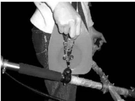
Always use the shoulder strap. Adjust and fix the belt and belt clamping plate on the device so that the device hangs a few cm above
the ground. The cut-out head and the protective shield should be aligned
horizontally in all directions. Pre-tension the devices on the right side of your body.
WARNING

Also, wear head, eye, face and hearing protection and safety shoes. Do not wear rings, jewellery or
loose, dangling clothes that could get caught in the device.
Do not wear footwear with unprotected toes, and do not work barefoot or without leg protection. In certain situations, you must wear head protection.
26. Putting on the shoulder harness

text_image
Illustration showing five different safety gear and device installation steps, labeled (1), with illustrations of a worker adjusting equipment.Important: The shoulder strap is an optional accessory from FUXTEC, which we recommend for use with any brush cutter job. You can find the shoulder strap at www.fuxtec.de via the following item number: FX-PS152TG
natural_image
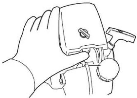
Close-up of a person holding a mechanical device with wires, no visible text or symbolsThe shoulder strap is equipped with a quick-release device (see picture). You can quickly remove the shoulder strap by pulling on the quick-release device.
Read the manual carefully. Be thoroughly familiar with the control and correct use of the device. Understand how to stop and shut down the device. Understand how to release a clamped attachment quickly.
Do not allow anyone to enter the DANGER ZONE while working. The DANGER ZONE is an area of 15 meters in radius (approximately 16 steps). Insist that people in the DANGER ZONE wear eye protection against flinging objects. If the device must be used where people are unprotected, work at a low, reduced speed to reduce the risk of skidding.
text_image
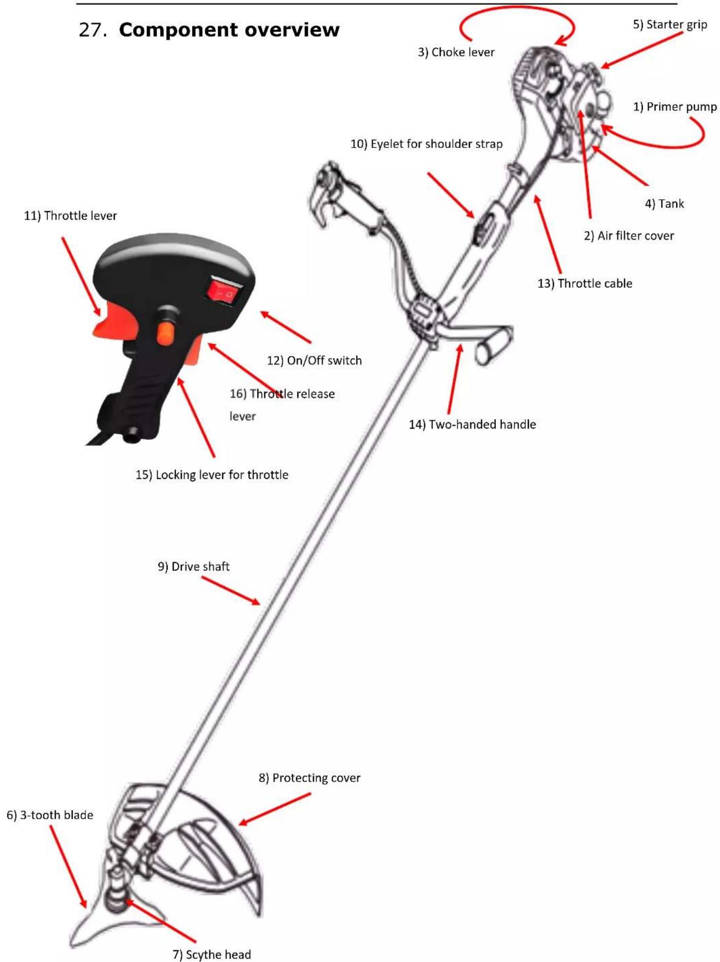
27. Component overview 1) Starter grip 5) Choke lever 1) Primer pump 4) Tank 10) Eyelet for shoulder strap 2) Air filter cover 13) Throttle cable 14) Two-handed handle 15) Locking lever for throttle 16) Throttle release lever 12) On/Off switch 9) Drive shaft 8) Protecting cover 6) 3-tooth blade 7) Scythe head28. Mounting the device
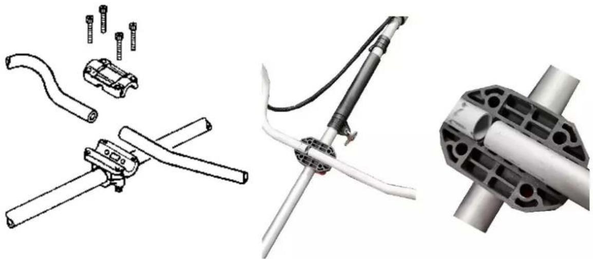
Attaching the handle
The handle must be fitted before use.
Follow the illustrations below for the correct installation.
- Loosen the 4 screws on the top cap and insert the handles. Tighten the screws again.
- Place the handle unit in the holder and slide the top cap over it. Tighten the cap firmly.
natural_image
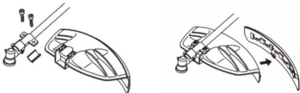
Technical illustration of mechanical components including crimping tools, a motor, and a cylindrical housing (no text or symbols)Installing the protective shield
Install the protective shield with the opening facing downwards towards the gearbox housing. Tighten the holder of the guard so that the blade guard does not move or slide down during operation. When using the 3-tooth blade or other blades, remove the protective collar (if present) from the protective shield!
natural_image
Technical line drawings of a mechanical assembly with no visible text or symbolsInstallation of the metal blade
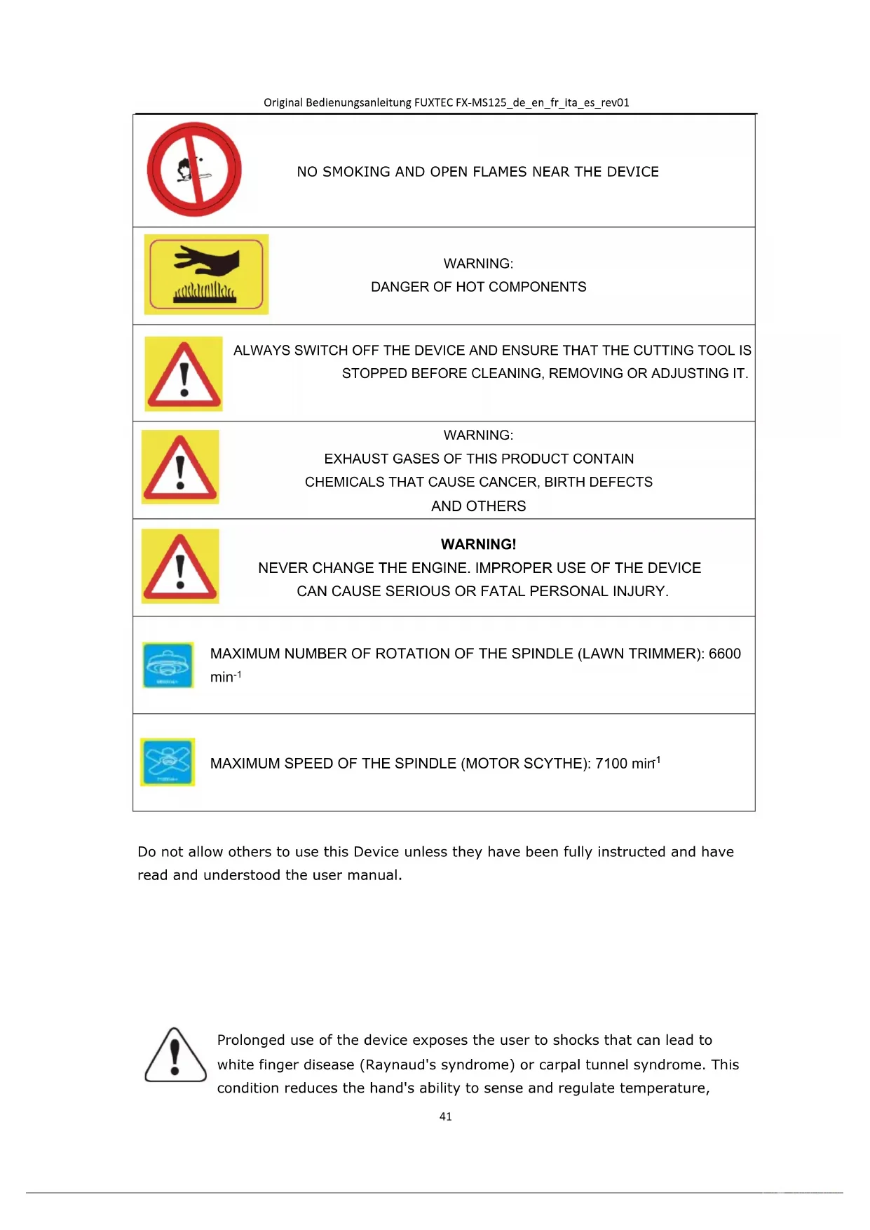
text_image
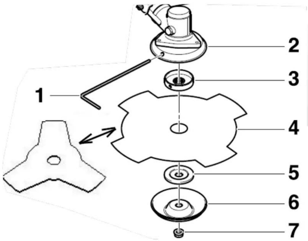
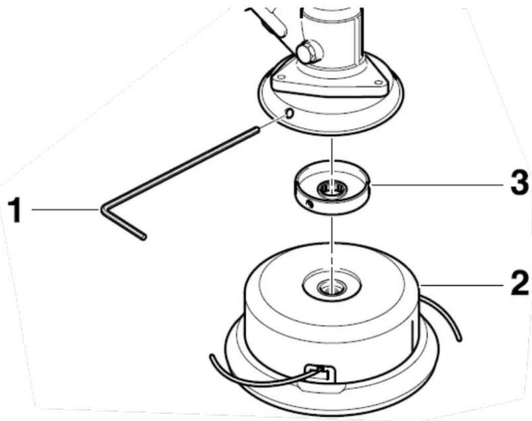
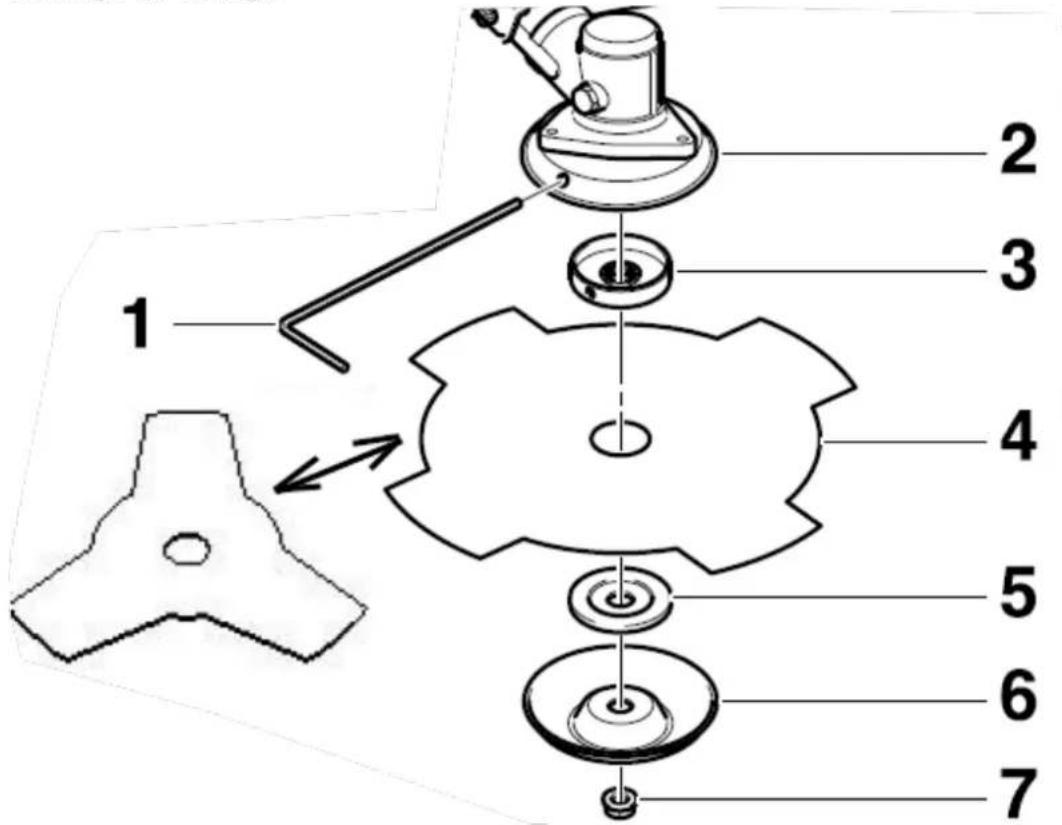
1 2 3 4 5 6 7Steps:
- Remove the safety cotter pin (if present). - Unscrew the lock nut (7) from the shaft by turning it clockwise. If necessary, block the sensor head (2) using the Allen key (1) (see the above picture). Note: The lock nut has a left-hand thread.
- Remove the disc washer (6) and washer (5).
- Use the Allen key (1) to block the scythe head. If necessary, turn the fastening disc (3) slightly.
- Position the blade (4), washer (5) and disc (6) as shown.
- Screw on the lock nut (7) and tighten it counterclockwise using the ring spanner.
- Attention! For safety reasons, the lock nut (C7) must be replaced with a new one after every 10 tool changes.
- Reattach the cotter pin.
- Remove the Allen key and check the freedom of movement of the cutting tool.
Installation of the lawn trimmer (thread spool)
text_image
1 2 3- Place the fastening disc (3) on the shaft.
- Use the Allen key (1) to lock the scythe head. If necessary, turn the fastening disc (3) slightly.
- Screw the thread spool (2) onto the shaft by turning it anticlockwise.
- Now tighten the thread spool by hand.
- Remove the Allen key and check the smooth running of the thread spool.
Warning!

Ensure that all components are correctly assembled and installed and that all screws are tightened.
FUEL AND 2-STROKE OIL
Use unleaded petrol with 2-stroke engine oil in a 40:1 ratio.
WARNING: Never use just fuel in your engine. This will cause permanent engine damage and void the manufacturer's warranty for this product. Never use a fuel mixture that has been stored for more than 90 days.
WARNING: This must be a premium grade, 2-stroke air-cooled engine oil.
FUEL MIXTURE
Mix fuel with 2-stroke oil in a container provided for this purpose. Note the following mixture table on the following page for the correct fuel/oil ratio. Shake the tank to ensure complete mixing.
| Petrol | Two-stroke engine oil (40:1) | Petrol | Two-stroke engine oil (40:1) |
| 1 litre | 0.025 litre | 5 litre | 0.125 litre |
| 2 litre | 0.050 litre | 10 litre | 0.250 litre |
WARNING: Failure to lubricate the engine eliminates the liability of the device manufacturer.
Petrol and oil must be mixed in a ratio of 40:1.
Recommended fuel
It is recommended to use unleaded petrol with an octane number of 90 # or higher to reduce carbon deposition in the combustion chamber. Do not use old or dirty petrol. Keep the fuel tank dust-free and avoid water getting into the tank. Sometimes misfiring can occur in case of overload, which is normal.
If the backfiring can be heard under average load, we recommend replacing the petrol. If the misfire is still present afterwards, don't hesitate to contact our customer service.

WARNING
text_image
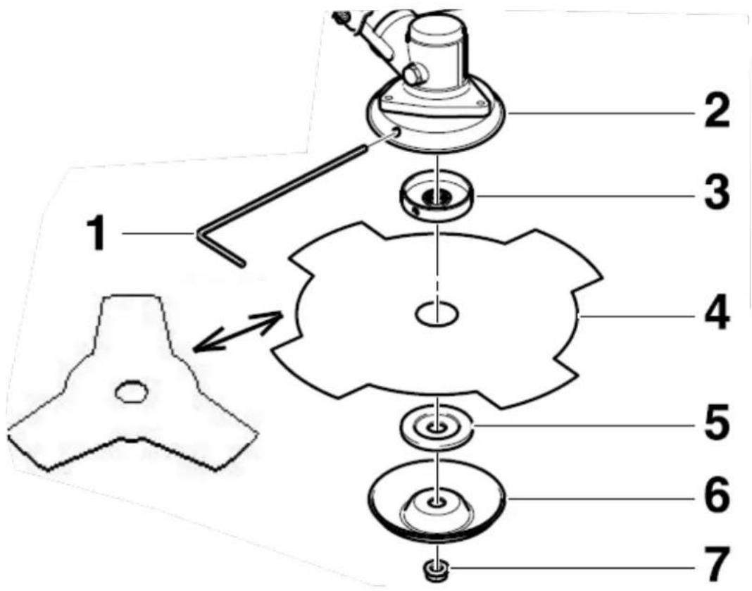
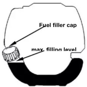
Fuel filler cap max filling level- Petrol is highly flammable and can cause an explosion in case of sparks
-
Refuel only in well-ventilated rooms and allow the engine to cool down before filling. Do not smoke during refuelling. Open fires and sparks must be avoided.
-
Do not overfill the tank (see figure max. filling level).
● After refuelling, check that the fuel filler cap is closed correctly. - Avoid any spillage of petrol.
- Keep the device away from children.
29. Starting the engine
Cold Start
CAUTION: The scythe head starts to rotate when the engine is started.
- Fill the fuel tank with gasoline and tighten the cap.
- Place the machine on a flat, firm surface. Keep the mower attachment off the ground and away from surrounding objects, as it will start to rotate when the engine is started.
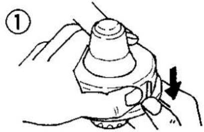
- Press the primer pump several times.
natural_image
Line drawing of a hand holding a small object with a hammer and scale, no text or symbols present- Move the choke lever to the closed position.
text_image
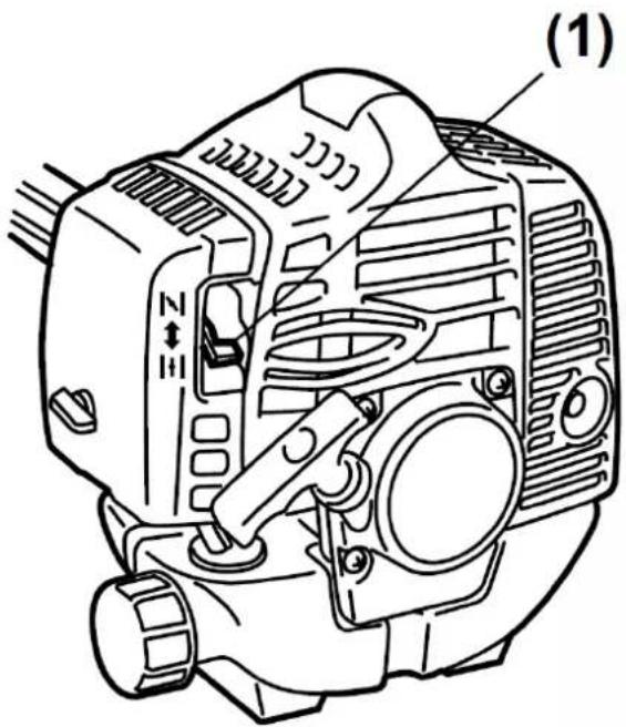
(1)
text_image
|←| (2) ↑ ||| (3)(1) Choke lever
(2) closed
(3) open
- Starter handle: set the on/off switch to 1
- Hold the device and carefully pull out the starter rope until you feel the first resistance. This is the starting position for the pull starter. Now pull the rope several times until the engine starts and runs.
Avoid pulling the rope to the end or letting it recoil by releasing the handle. Such actions may cause the starter to fail.
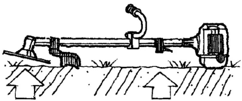
IMPORTANT: The device is equipped with a centrifugal clutch so that the cutting tool starts moving as soon as the engine is put into the start position by operating the throttle. When starting the engine, place the product on the ground in a level, clear area and hold it firmly so that neither the cutting part nor the throttle lever can come into contact with any obstacle when starting the engine.
natural_image
Diagram of a mechanical device with attached pipe and lever, showing ground level and upward arrows (no text or symbols)- Allow the engine to warm up for a few minutes at idle after starting before starting work!
NOTE: If the machine does not start after repeated attempts, please read the troubleshooting chapter.
NOTE: Always pull the starter rope straight out. Pulling the starter at an angle will cause the rope to rub against the eyelet. The diagonal pull can cause the starter rope to fray or break. Always hold the starter handle when the rope retracts. Never allow the rope to be thrown back from the pulled-out position. This could damage the starter device.
Warm start of the engine
- Place the device on a firm and flat surface.
- Switch the ON/OFF to 1.
- Slide the choke to the "OPEN" position.
- Pull out the starter rope with a short-stroke until resistance is felt (about 100mm). A continuous, mainly fast pull will provide a strong spark and start the engine.
If the engine does not start, please proceed again according to "Cold starting the engine."
30. Stopping the device
Unlock the throttle lever. Allow the device to return to idle. Press the engine stop switch on the handle (position 0) and wait until the machine stops. If it does not stop, disconnect the spark plug connector in an emergency. Never leave the device unattended while it is running.
31. Trimming techniques
ADDITIONAL SAFETY INSTRUCTIONS
Before running your device, read notes in chapters 3 and 4 of this manual.
CAUTION
IF YOU are NOT familiar with the trimming techniques, practice with the DEVICE in the "STOP" position (turned off).
ALWAYS TRIM OR CUT AT HIGH ENGINE SPEEDS. Never run the device slowly at the beginning of (or during) the trimming operation.
ALWAYS MAKE AWAY DISTANCE IN THE WORKING AREA from cans, bottles, rocks, etc. Whirling objects can cause serious injury to users or bystanders and damage the device. If an object is accidentally knocked, immediately stop the ENGINE and check the device. Never run the device with damaged or defective parts.
Never lift the nylon cutting head above knee height during operation. Never run the device on a slope if there is a chance of sliding or losing stability.
RELEASING THE NYLON THREAD

To release the new thread, run the engine at full throttle and tap the nylon cutting head onto the lawn. The threaded head automatically releases further threads. The blade in the protective shield cuts off the excess thread.

CAUTION: Remove grass deposits regularly to prevent overheating of the drive axle. Grass deposits occur when fibres of the weed are entangled around the shaft under the protective shield. This prevents the shaft from cooling correctly. Remove grass deposits with a screwdriver or similar tool only when the device is switched off.

natural_image
Technical line drawing of a mechanical device with a downward arrow indicator (no text or symbols present)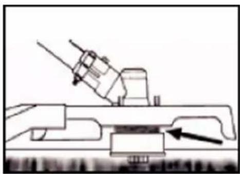
natural_image
Technical line drawing of a mechanical assembly with no visible text or symbolsWhen the device is appropriately equipped with a protective shield and nylon cutting head, your device will trim unsightly weeds and large-diameter tall grass in areas along fences, walls, land, and around trees.
NOTE: Pay particular attention when trimming on brick or stone walls, etc., where rapid weed wear will occur.
Swing the trimmer's nylon cutting head horizontally from side to side. Do not tilt the nylon cutting head while working. For correct cutting height, trim in a test area beforehand. Keep nylon cutting head at the same level for even depth of cut.
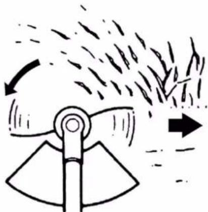
TRIMMING AROUND TREES
Trim around logs with a slow approach; the thread
should not collide with the log. Walk around the tree from left to right—approach grass or weeds with the tip of the thread.
natural_image
Diagram of a mechanical device emitting particles from a fan-like structure, with no visible text or symbols.32. Replacing Nylon Thread
natural_image
Illustration of hands using a mechanical tool to adjust a component (no text or symbols present)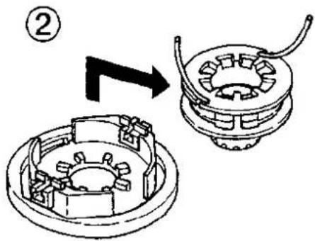
text_image
Technical diagram showing mechanical assembly with labeled component (②) and directional arrow indicating process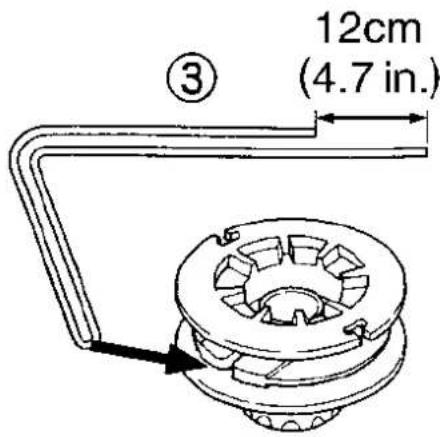
text_image
③ 12cm (4.7 in.)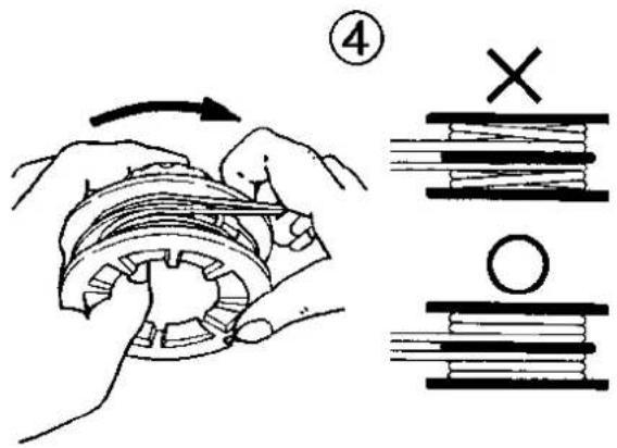
text_image
Diagram illustrating mechanical assembly steps with labeled components and directional arrows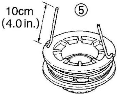
text_image
10cm (4.0 in.) ⑤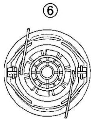
natural_image
Technical line drawing of a mechanical component with concentric rings and internal slots (no text or symbols)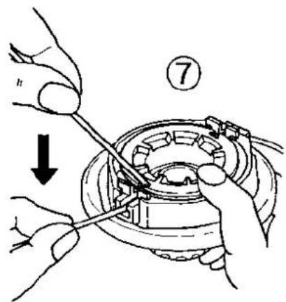
text_image
Technical diagram showing hands assembling a mechanical component with a numbered step and directional arrow indicating motion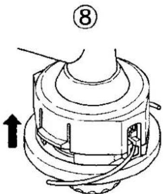
text_image
⑧- As a replacement line, use a diameter of 2.4mm (.095in). The spool is suitable for line up to 6m (20ft) on the 10cm (4") head. Avoid using a larger cord, as this may affect trim performance.
CAUTION: For safety reasons, do not use metal-reinforced cord
- Squeeze the slotted area on both sides of the spool housing to unhook the lower cap.
- Take out the spool and pull off the old cord. Put one end of the new cord through the spool holes and pull it until the length between the two parts of the cord is the same.
- Wind the string in the correct direction as indicated on the cord.
- Hook each end of the string into the slot on the spool's edge and put the ends through the eyelets on the housing. Make sure that the spring and washers are in place.
- Hold the spool against the housing and pull the ends of the cord to release it from the slot.
- Align the slot on the lower cap with the hook on the housing and press the cap against the housing until it clicks into place.
33. Maintenance schedule
Regular checks and adjustments must be made to ensure that the petrol engine maintains its performance. Periodic maintenance also provides a long service life. See the following table for the regular maintenance cycle.
| MaintenancecycleComponent | Each use | Every month or 10h | Every 3 months or 25h | Every 6 months or 50h | Every 12 months or 100h | Every 2 years or 300h | |
| Air filter | Check | ■ | |||||
| Clean up | ■a | ||||||
| Spark plug | Check & adjust | ■ | |||||
| Exchange | ■ | ||||||
| Spark plug connector (optional) | Clean up | ■ | |||||
| Cooling fins | Audit | ■ | |||||
| Connecting elements such as screws and nuts | Check (tighten if necessary) | ■ | |||||
| Coupling | Audit | ■b | |||||
| Idle speed | Check and adjust | ■b | |||||
| Valve clearance | Check and adjust | ■b | |||||
| Combustion chamber | Clean up | 300 h after that | |||||
| Fuel | Check | ■ | |||||
| Fuel tank | Check | ■ | |||||
| Fuel line | Check | Every x years (replace if necessary) | |||||
WARNING

a. Increase maintenance intervals if working in dusty environments.
b. All maintenance work - except for that listed in the operating manual - must be carried out at regular intervals.
Work must be carried out by qualified maintenance personnel.
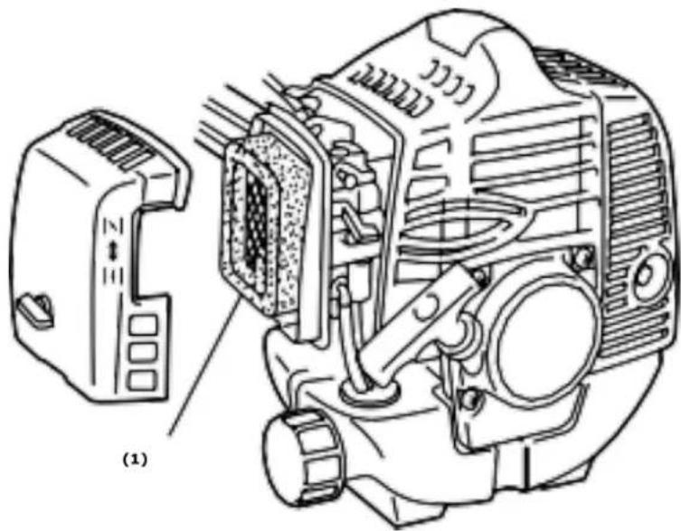
Cleaning the air filter
CAUTION: Never run the engine without the air filter.
A dirty air filter puts pressure on engine performance, increases fuel consumption, and makes starting more difficult. If you notice a loss of engine power:
1 Remove the screw on the filter cover and take out the filter.
2 Clean the filter with soap and water. Never use petrol or benzene!
3 Let the filtered air dry.
4 Put the filter back in place and fasten the filter cover with the screw.
natural_image
Technical line drawing of a mechanical assembly with a component labeled (1), showing internal components and no readable text or symbols.Spark plug maintenance
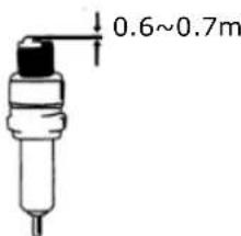
To ensure the normal operation of the engine, the ignition distance of 0.6 -0.7mm must be maintained and must be free of carbon deposits. Always carry out the following steps with the engine switched off:
-
Carefully remove the spark plug connector. Do not pull on the cable but directly on the connector.
-
Use the spark plug wrench supplied to unscrew the spark plug.
-
Visually check the spark plug for damage and electrode burn-off, Remove the carbon deposits.
-
Check the gap with a feeler gauge and bend the electrode to the correct distance of 0.6 to 0.7mm.
-
Check the spark plug washer and tighten the spark plug to a torque of 12-15 Nm.
text_image
0.6~0.7m- Put the ignition cap back on the spark plug.

WARNING
The spark plug must be screwed down tightly; otherwise, the engine runs hot and is damaged.
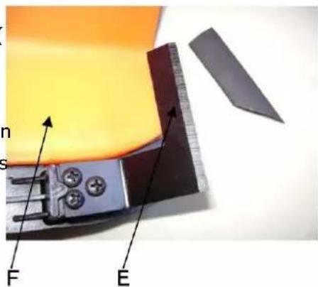
Sharpen the shielded knife
-
Remove the cutting blade (E) from a protective shield (
-
Clamp the knife in a vice.
Sharpen the knife with a flat-file.
Please make sure that you maintain the angle of the cutting. Only move the grinding blade in one direction during the s
text_image
F E34. Storage of the device

WARNING: Failure to follow these steps may result in the formation of deposits in the carburettor. This will make it challenging to start later and can cause permanent damage.
-
Perform all general maintenance as described in the maintenance section of your user manual are recommended.
-
Clean the exterior of the device, drive axle, protective shield, and nylon cutting head.
-
Drain the fuel from the fuel tank.
-
After draining the fuel, start the engine.
-
Let the engine run in neutral until it stops by itself. This will clean the carburettor of fuel.
-
Let the engine cool down (about 5 minutes).
-
Use a spark plug wrench, and remove the spark plug.
-
Pour 1 teaspoon of clean 2-stroke oil into the combustion chamber. Pull the starter cord
slowly several times to coat the internal components. Replace the spark plug if necessary.
- Store the device in a cool, dry place away from any source of ignition, such as an oil burner, water heater, etc.
TRANSPORT PROTECTION
Ensure the device is well-secured during transport to avoid fuel loss, damage, or injury. Install transport protection for metal sheets during transport and storage.
35. Troubleshooting
- Difficulties during commissioning
| Situation | Cause | Solution | |
| No ignition spark | Spark plug | Carbon deposit between the diodes of the spark plug | Clean the spark plug. Adjust the gap 0.6~0.7mm, replace the spark plug |
| other | Ignition coil defective flywheel magnet too weak | Replace the ignition coil or flywheel | |
| Weak ignition spark | Compression | Too much petrol in the combustion chamber, lousy fuel or water in the tank | Remove the spark plug and allow it to dry, and replace the fuel. |
| The carburettor does not pump oil anymore. | Oil line blocked | Cleaning the carburettor and cleaning the pipes | |
| regular oil supply, but weak compression | Piston rings are worn, the spark plug is not screwed down, the cylinder head is not tight, wrong valve clearance or ignition timing. | Replace the screw tight to replace or adjust | |
| regular oil supply and proper ignition spark | Poor contact between the ignition cap and spark plug | Replace or check | |
- Difficulties during operation
| Situation | Cause | Solution |
| The engine does not reach the speed | Choke is in "COLD START" position, the exhaust system is blocked no air supply, moving elements worn, ignition spark weak too large valve clearance, cylinder head sooty | Open choke, replace exhaust systemCheck or replace ignition coil, adjust flywheel, spark plug |
| Operating materials are leaking | Lines to carburetor blocked Spark plug spacing incorrect | Replace lines and carburetor Adjust gap dimension |
| Motor-Noises | Wrong choke position,Camshaft damaged | Check/replace camshaft |
| Carburetor leaking | Failure of the check valve on the tank cap | Replace the fuel filler cap |
| Carburetor gasket is worn out | Replace carburetor or gasket |

If no troubleshooting solves the problem, please contact the FUXTEC customer service. Only use original parts approved by the manufacturer. Otherwise, there is a risk of danger.
- Customer Service
Have your purchased device repaired only by qualified personnel and only with original spare parts. This will ensure that the safety of the device is maintained.
Please contact the manufacturer FUXTEC GmbH directly at www.fuxtec.co.uk at any time regarding maintenance work and the procurement of spare parts.
- Warranty
The warranty period is 24 months from the date of purchase. Please keep your proof of purchase in a safe place. Excluded from the warranty are wearing parts and damage caused by improper use, use of force, technical modifications, use of incorrect accessories or non-original spare parts, and repair attempts by non-qualified personnel. Warranty repairs may only be carried out by authorized specialist dealers.
- Disposal note
Please contact your local municipality for the disposal of the device. Please dispose of all operating materials such as petrol and oil in advance.
36. EC Declaration of Conformity
We hereby declare,
FUXTEC GMBH
KAPPSTRAße 69, 71083 HERRENBERG, GERMANY
that the device described below, by its design and construction and in the version marketed by us, complies with the relevant essential health and safety requirements of the EC directives.
Designation of the device:
Petrol motor scythe/lawn trimmer
Engine type:
FX-MS125
Trademark:
FUXTEC
Power consumption/displacement
25,4cm ^3
Measured sound power level
LWA = 107.7dB
Guaranteed sound power level
LWA=114dB
Conformity procedure 2000/14/EC according to Annex V
EC machine straightening thread 2006/42/EC
Relevant EC straightening thread:
EC directive on electromagnetic compatibility (EMC)
2004/108/EC
EC-directive thread Noise emission (2000/14/EWG & 2005/88/EC)
Applied harmonized
EN ISO 11806-1
Standards:
EN ISO 14982
Manufacturer signature/date:
C. Jille
Leonhard Zirkler, 06.12.2022
Name and address of the
L. Zirkler
person authorized to compile the technical documentation
FUXTEC GMBH - KAPPSTRAße 69, 71083 HERRENBERG,
established within the
GERMANY
Community
MODE D'EMPLOI ORIGINAL
natural_image
Mechanical tool with articulated arm and bucket cover (no visible text or symbols)natural_image
Illustration of five different safety gear and equipment setups, including a worker adjusting helmet, hand positioning, and a handheld device (no text or symbols present)natural_image
Person using a mechanical tool to lift a cylindrical component, no visible text or symbolsnatural_image
Technical illustration of mechanical components including crimping tools, a motor, and a cylindrical housing (no text or symbols)natural_image
Technical line drawings of a mechanical component assembly (no text or symbols)natural_image
Line drawing of hands using a tool to adjust or install a mechanical component (no text or symbols present)natural_image
Diagram of a mechanical device with a curved handle and directional arrows, no text or symbols presentnatural_image
Diagram of a naval gun firing from a ship deck, showing blade and gear components (no text or symbols)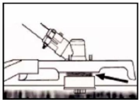
natural_image
Technical line drawing of a mechanical assembly with an arrow indicating a component (no text or symbols present)natural_image
Diagram of a wind turbine blade with motion arrows indicating airflow or vibration (no text or symbols)DÉCOUPAGE AUTOUR DES ARBRES
natural_image
Technical line drawing of a mechanical assembly with a close-up view of a component (no text or symbols)text_image
0.6~0.7mm
AVERTISSEMENT
natural_image
Close-up of a mechanical component with labeled parts F and E, showing internal components and a ruler-like structure (no readable text or symbols beyond labels)50. Stockage de la machine

natural_image
Black and white photo of a FUTECV-branded manual scrubber with attached sensor device (no visible text or symbols)text_image
Illustration showing five different safety gear and device installation steps, labeled (1), with illustrations of workers in protective gear.natural_image
Person holding a mechanical device with attached wires, black and white photo (no visible text or symbols)natural_image
Technical illustration of mechanical components including crimping rods, fasteners, and a motor assembly (no text or symbols)natural_image
Technical line drawings of a mechanical assembly with no visible text or symbolstext_image
Technical diagram of a mechanical assembly with numbered parts, likely a valve or pump component.Passi:
natural_image
Line drawing of hands using a tool to adjust or install a component (no text or symbols present)natural_image
Simple line drawing of a mechanical device with a curved handle and base, resting on a textured surface with directional arrows (no text or symbols)natural_image
Diagram of a naval gun firing from a ship deck, showing blade and gear components (no text or symbols)
natural_image
Technical line drawing of a mechanical assembly with an arrow indicating a component (no text or symbols present)natural_image
Diagram of a mechanical device emitting particles from a fan, with arrows indicating motion (no text or symbols)TAGLIARE INTORNO GLI ALBERI
text_image
0.6~0.7mmAVVERTENZE

natural_image
Close-up of a mechanical component with labeled parts (F, E) and a ruler, showing no readable text or symbols.natural_image
Black and white photo of a FUTECV-branded manual scrubber with attached sensor device (no visible text or symbols)text_image
15m (50 ft)MANTENGA SIEMPRE 15 METROS DE DISTANCIA CON OTRAS PERSONAS

EL NIVEL DE RUIDO GARANTIZADO CUMPLE CON LAS NORMAS LEGALES SOBRE RUIDO


NO FUMAR NI UTILIZAR LLAMAS LIBRES CERCA DEL APARATO
text_image
Illustration showing five different safety gear and equipment installation steps, labeled (1), with illustrations of workers in protective gear.natural_image
Person holding a mechanical device with attached wires, black and white photo (no visible text or symbols)natural_image
Technical illustration of mechanical components including crimping tools, a motor, and a cylindrical housing (no text or symbols)natural_image
Technical line drawing showing two mechanical assembly steps with no visible text or symbolsMontaje de la hoja
text_image
1 2 3 4 5 6 7Pasos:
MEZCLA DE COMBUSTIBLE
natural_image
Line drawing of a hand using a hammer to adjust or install a mechanical component (no text or symbols present)natural_image
Diagram of a mechanical device with a curved handle and directional arrows, no text or symbols presentnatural_image
Diagram of a naval gun firing with a downward arrow indicating force (no text or symbols present)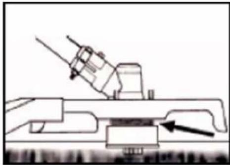
natural_image
Technical line drawing of a mechanical assembly with an arrow indicating a component (no text or symbols present)natural_image
Diagram of a mechanical device emitting particles or smoke, with arrows indicating direction (no text or symbols)CORTANDO ALREDEDOR DE LOS ÁRBOLES
natural_image
Technical line drawing of an automotive engine component, showing internal parts and a close-up view (no text or symbols)text_image
0.6~0.7mm