
GP5V - Sander HiKOKI - Free user manual and instructions
Find the device manual for free GP5V HiKOKI in PDF.

| Brand | HiKOKI |
| Model | GP5V |
| Product type | Straight grinder (sander) |
| Power | 760 W |
| No-load speed | 2000 – 8300 rpm |
| Rated speed | 8820 rpm |
| Maximum grinding wheel diameter | 50 mm |
| Collet chuck capacity | 6 mm |
| Weight (without cable) | 1.9 kg |
| Supply voltage | 110-240 V~ |
| Speed control | Electronic continuously variable (dial 1 to 6) |
| Main functions | Grinding, sanding, sharpening, deburring, polishing |
| Side handle | Included (except some regions) |
| Safety | Safety stop, restart protection, mandatory guard |
| Routine maintenance | Cleaning vents, inspecting and replacing carbon brushes |
| Available spare parts | Brushes, collet chuck (3/6/8 mm), grinding wheels, wrenches, side handle, rear cover |
| Repairability | Repairs by HiKOKI authorized service only |
| Sound level | 93 dB(A) (acoustic pressure) |
| Vibrations | 4.0 m/s² (finishing grinding) |
| Warranty | According to national regulations |
Frequently Asked Questions - GP5V HiKOKI
User questions about GP5V HiKOKI
0 question about this device. Answer the ones you know or ask your own.
Ask a new question about this device
Download the instructions for your Sander in PDF format for free! Find your manual GP5V - HiKOKI and take your electronic device back in hand. On this page are published all the documents necessary for the use of your device. GP5V by HiKOKI.
USER MANUAL GP5V HiKOKI
natural_image
Illustration of two types of industrial power tools with no visible text or symbolsGP3V GP5V
Read through carefully and understand these instructions before use.
2
3
4
5
6
natural_image
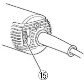
Technical line drawing of a mechanical component with a numbered label (15), no readable text or symbols present.| English Deutsch | Français Italiano | |||
| 1 | Tapered portion Verjüngter | Teil Partie conique Parte conica | ||
| 2 | Collet chuck Spannfutter | Mandrin à collet Bussola di chiusura | ||
| 3 | Spindle Welle Broche Albero | |||
| 4 | Tighten Anziehen Fixation | Serrare | ||
| 5 | Collet chuck Spannfutter | Mandrin à collet Bussola di chiusura | ||
| 6 | Side handle | Seitengriff | Poignée latérale | Maniglia laterale |
| 7 | Side handle sleeve | Seitengriffmuffe | Manchon de la poignée latérale | Manicotto della maniglia laterale |
| 8 | Side handle grip | Spannfutter für Seitengriff | Fixation de la poignée latérale | Impugnatura della maniglia laterale |
| 9 | Flange part | Flanschteil | Bride | Parte della flangia |
| 10 | Wear limit | Verschleißgrenze | Limite d’usure | Limite di usura |
| 11 | No. of carbon brush | Nr. der Kohlebürste | No. de balai en carbone | N. delle spazzole di carbone |
| 12 | Spring | Feder | Ressort Molla | |
| 13 | Carbon brush | Kohlebürste | Balai en carbone | Spazzola di carbone |
| 14 | Brush holder | Bürstenhalter | Support de balai | Portaspazzola |
| 15 | Dial | Skalenscheibe | Bague | Manopola |
| Nerderlands | Español | Português | |
| 1 | Taps gedeelte | Parte cónica | Parte cónica |
| 2 | Klembus | Boquilla de mordazas | Mandril de colar |
| 3 | Spil | Husillo | Eixo |
| 4 | Vastzetten | Apretar | Apertar |
| 5 | Klembus | Boquilla de mordazas | Mandril de colar |
| 6 | Zijhandgreep | Asidero lateral Pega lateral | |
| 7 | Zijhandgreepmof | Funda del asidero lateral | Manga da pega lateral |
| 8 | Zijhandvat | Empuñadura del asidero lateral | Punho da pega lateral |
| 9 | Flensgedeelte Parte de la brida | Flange | |
| 10 | Slijtagegrens | Límite de desgaste | Limite de desgaste |
| 11 | Nr. van koolborstel | No. de escobilla de carbón | No de escova de carvão |
| 12 | Veer | Resorte | Mola |
| 13 | Koolborstel | Carbón de contacto | Escova de carvão |
| 14 | Borstelhouder | Portaescobilla Suporte de escova | |
| 15 | Draaiknop | Dial | Botão |
| Symbols⚠ WARNINGThe following show symbols used for the machine. Be sure that you understand their meaning before use. | Symbole⚠ WARNUNGDie folgenden Symbole werden für diese Maschine verwendet. Achten Sie darauf, diese vor der Verwendung zu verstehen. | Symboles⚠ AVERTISSEMENTLes symboles suivants sont utilisés pour l’outil. Bien se familiariser avec leur signifi cation avant d’utiliser l’outil. | Simboli⚠ AVVERTENZADi seguito mostriamo i simboli usati per la macchina. Assicurarsi di comprenderne il signifi cato prima dell’uso. | |
 | To reduce the risk of injury, user must read instruction manual.Failure to follow the warnings and instructions may result in electric shock, fi re and/or serious injury. | Der Anwender muss die Bedienungsanleitung lesen, um das Risiko einer Verletzung zu verringern.Wenn die Warnungen und Anweisungen nicht befolgt werden, kann es zu Stromschlag, Brand und/oder ernsthaften Verletzungen kommen. | Pour réduire les risques de blessures, l’utilisateur doit lire le manuel d’utilisation.Tout manquement à observer ces avertissements et instructions peut engendrer des chocs électriques, des incendies et/ou des blessures graves. | Per ridurre il rischio di lesioni, l’utente deve leggere il manuale delle istruzioni.La mancata osservanza degli avvertimenti e delle istruzioni potrebbe essere causa di scosse elettriche, incendi e/o gravi lesioni. |
 | Always wear eye protection. | Tragen Sie immer einen Augenschutz. | Toujours porter des verres de protection. | Indossate sempre le protezioni oculari. |
 | Only for EU countriesDo not dispose of electric tools together with household waste material!In observance of European Directive 2002/96/EC on waste electrical and electronic equipment and its implementation in accordance with national law, electric tools that have reached the end of their life must be collected separately and returned to an environmentally compatible recycling facility. | Nur für EU-Länder Werfen Sie Elektrowerkzeuge nicht in den Hausmüll!Gemäss Europäischer Richtlinie 2002/96/EG über Elektro- und Elektronik- Altgeräte und Umsetzung in nationales Recht müssen verbrauchte Elektrowerkzeuge getrennt gesammelt und einer umweltgerechten Wiederververtung zugeführt werden. | Pour les pays européens uniquementNe pas jeter les appareils électriques dans les ordures ménagères!Conformément à la directive européenne 2002/96/EG relative aux déchets d’équipements électriques ou électroniques (DEEE), et à sa transposition dans la législation nationale, les appareils électriques doivent être collectés à part et être soumis à un recyclage respectueux de l’environnement. | Solo per Paesi UENon gettare le apparecchiature elettriche tra i rifi uti domestici.Secondo la Direttiva Europea 2002/96/CE sui rifi uti di apparecchiature elettriche ed elettroniche e la sua attuazione in conformità alle norme nazionali, le apparecchiature elettriche esauste devono essere raccolte separatamente, al fi ne di essere reimpiegate in modo eco-compatibile. |
| n_0 | no-load speed Leerlaufdrehzahl Vitesse à vide Velocità | a vuoto | ||
| n | Rated Speed Umdrehungszahl Vitesse nominale Velocità nominale | |||
| min-1 | Revolutions or reciprocations per minute | Umdrehungen oder Pendelbewegungen pro Minute | Tours ou mouvements alternatifs par minute | Rivoluzioni o reciprocazioni per minuto |
| ~ | Alternating current Wechselstrom Courant alternatif Corrente alternata | |||
 | Class II tool Werkzeug der Klasse II Outil classe II Attrezzo di Classe II | |||
| ⚠️ | Caution | Achtung | Attention | Attenzione |
| Symbolen⚠ WAARSCHUWINGHieronder staansymbolen afgebeeld dievan toepassing zijn opdeze machine. U moetde betekenis hiervanbegrijpen voor gebruik. | Símbolos⚠ ADVERTENCIAA continuación semuestran los símbolosusados para lamáquina. Asegúresede comprender susignifi cado antes del uso. | Símbolos⚠ AVISOA seguir aparecem ossímbolos utilizados pelamáquina. Assimile bemseus signifi cados antesdo uso. | |
 | Om het risico opverwondingen teverminderen, moetde gebruiker deinstructiehandleidinglezen.Nalating om dewaarschuwingen instructies op te volgenkan in een elektrischeschok, brand en/of ernstigletsel resulteren. | Para reducir el riesgode lesiones, el usuariodeberá leer el manualde instrucciones.Si no se siguenlas advertencias einstrucciones, podríaproducirse una descargaeléctrica, un incendio y/odaños graves. | Para reduzir o riscode lesão, o utilizadordeve ler o manual deinstruções.Se não seguir todas asinstruções e os avisos,pode provocar um choqueeléctrico, incêndio e/ouferimentos graves. |
 | Draag altijdoogbescherming. | Utilice siempre unaprotección ocular. | Utilize sempre protecçãopara os olhos. |
 | Alleen voor EU-landenGeef elektrischgereedschap niet methet huisvuil mee!Volgens de Europeserichtlijn 2002/96/EGinzake oude elektrischeen elektronischeapparaten en detoepassing daarvanbinnen de nationalewetgeving, dient gebruiktelektrisch gereedschapgescheiden te wordeningezameld en teworden afgevoerd naareen recycle bedrijf datvoldoet aan de geldendemilieu-eisen. | Sólo para países de laUnión Europea¡No deseche los aparatoseléctricos junto con losresiduos domésticos!De conformidad conla Directiva Europea2002/96/CE soberesiduos de aparatoseléctricos y electrónicosy su aplicaciónde acuerdo con lalegislación nacional,las herramientaseléctricas cuya vida útilhaya llegado a su fi n sedebérán recoger porseparado y trasladar aunaplanta de reciclajeque cumpla con lasexigencias ecológicas. | Apenas para países daUENão deite ferramentaseléctricas no lixodoméstico!De acordo com a directivaeuropeia 2002/96/CEsobre ferramentaseléctricas e electrónicasusadas e a transposiçãopara as leis nacionais, asferramentas eléctricasusadas devem serrecolhidas em separadoe encaminhadas a umainstalação de reciclagemdos materiais ecológica. |
| n_0 | snelheid onbelast velocidad | sin carga velocidade sem carga | |
| n | Gekwalifi ceerdesnelheid | Velocidad nominal Velocidade nominal | |
| min-1 | Toerental of heen-en-weer gaande bewegingper minuut. | Revoluciones o giros porminuto | Rotações ou alternaçõespor minuto |
| ~ | Wisselstroom Corriente alterna Corrente alternada | ||
 | Gereedschap klasse II Herramienta de Clase II Feramenta de classe II | ||
 | Voorzichtig Precaución Alenção | ||
GENERAL POWER TOOL SAFETY WARNINGS

WARNING
Read all safety warnings and all instructions.
Failure to follow the warnings and instructions may result in electric shock, fire and/or serious injury.
Save all warnings and instructions for future reference.
The term “power tool” in the warnings refers to your mains-operated (corded) power tool or battery-operated (cordless) power tool.
1) Work area safety
a) Keep work area clean and well lit.
Cluttered or dark areas invite accidents.
b) Do not operate power tools in explosive atmospheres, such as in the presence of fl ammable liquids, gases or dust.
Power tools create sparks which may ignite the dust or fumes.
c) Keep children and bystanders away while operating a power tool.
Distractions can cause you to lose control.
2) Electrical safety
a) Power tool plugs must match the outlet.
Never modify the plug in any way.
Do not use any adapter plugs with earthed (grounded) power tools.
Unmodifi ed plugs and matching outlets will reduce risk of electric shock.
b) Avoid body contact with earthed or grounded surfaces, such as pipes, radiators, ranges and refrigerators.
There is an increased risk of electric shock if your body is earthed or grounded.
c) Do not expose power tools to rain or wet conditions.
Water entering a power tool will increase the risk of electric shock.
d) Do not abuse the cord. Never use the cord for carrying, pulling or unplugging the power tool.
Keep cord away from heat, oil, sharp edges or moving parts.
Damaged or entangled cords increase the risk of electric shock.
e) When operating a power tool outdoors, use an extension cord suitable for outdoor use.
Use of a cord suitable for outdoor use reduces the risk of electric shock.
f) If operating a power tool in a damp location is unavoidable, use a residual current device (RCD) protected supply.
Use of an RCD reduces the risk of electric shock.
3) Personal safety
a) Stay alert, watch what you are doing and use common sense when operating a power tool. Do not use a power tool while you are tired or under the influence of drugs, alcohol or medication.
A moment of inattention while operating power tools may result in serious personal injury.
b) Use personal protective equipment. Always wear eye protection.
Protective equipment such as dust mask, non-skid safety shoes, hard hat, or hearing protection used for appropriate conditions will reduce personal injuries.
c) Prevent unintentional starting. Ensure the switch is in the off-position before connecting to power source and/or battery pack, picking up or carrying the tool.
Carrying power tools with your finger on the switch or energising power tools that have the switch on invites accidents.
d) Remove any adjusting key or wrench before turning the power tool on.
A wrench or a key left attached to a rotating part of the power tool may result in personal injury.
e) Do not overreach. Keep proper footing and balance at all times.
This enables better control of the power tool in unexpected situations.
f) Dress properly. Do not wear loose clothing or jewellery. Keep your hair, clothing and gloves away from moving parts.
Loose clothes, jewellery or long hair can be caught in moving parts.
g) If devices are provided for the connection of dust extraction and collection facilities, ensure these are connected and properly used.
Use of dust collection can reduce dust-related hazards.
4) Power tool use and care
a) Do not force the power tool. Use the correct power tool for your application.
The correct power tool will do the job better and safer at the rate for which it was designed.
b) Do not use the power tool if the switch does not turn it on and off.
Any power tool that cannot be controlled with the switch is dangerous and must be repaired.
c) Disconnect the plug from the power source and/or the battery pack from the power tool before making any adjustments, changing accessories, or storing power tools.
Such preventive safety measures reduce the risk of starting the power tool accidentally.
d) Store idle power tools out of the reach of children and do not allow persons unfamiliar with the power tool or these instructions to operate the power tool.
Power tools are dangerous in the hands of untrained users.
e) Maintain power tools. Check for misalignment or binding of moving parts, breakage of parts and any other condition that may affect the power tool's operation.
If damaged, have the power tool repaired before use.
Many accidents are caused by poorly maintained power tools.
f) Keep cutting tools sharp and clean.
Properly maintained cutting tools with sharp cutting edges are less likely to bind and are easier to control.
g) Use the power tool, accessories and tool bits etc. in accordance with these instructions, taking into account the working conditions and the work to be performed.
Use of the power tool for operations different from those intended could result in a hazardous situation.
5) Service
a) Have your power tool serviced by a repair person using only identical replacement parts.
This will ensure that the safety of the power tool is maintained.
PRECAUTION
Keep children and infi rm persons away.
When not in use, tools should be stored out of reach of children and infi rm persons.
SAFETY WARNINGS COMMON FOR GRINDING OPERATIONS
a) This power tool is intended grinder. Read all safety warnings, instructions, illustrations and specifications provided with this power tool.
Failure to follow all instructions listed below may result in electric shock, fi re and/or serious injury.
b) Operations such as a polishing or cutting-off are not recommended to be performed with this power tool.
Operations for which the power tool was not designed may create a hazard and cause personal injury.
c) Do not use accessories which are not specifically designed and recommended by the tool manufacturer.
Just because the accessory can be attached to your power tool, it does not assure safe operation.
d) The rated speed of the accessory must be at least equal to the maximum speed marked on the power tool.
Accessories running faster than their rated speed can break and fly apart.
e) The outside diameter and the thickness of your accessory must be within the capacity your power tool.
Incorrectly sized accessories cannot be adequately guarded or controlled.
f) Threaded mounting of accessories must match the grinder spindle thread. For accessories mounted by flanges, the arbour hole of the accessory must fit the locating diameter of the flange.
Accessories that do not match the mounting hardware of the power tool will run out of balance, vibrate excessively and may cause loss of control.
g) Do not use a damaged accessory. Before each use inspect the accessory such as abrasive wheels for chips and cracks, backing pad for cracks, tear or excess wear, wire brush for loose or cracked wires. If power tool or accessory is dropped, inspect for damage or install an undamaged accessory. After inspecting and installing an accessory, position yourself and bystanders away from the plane of the rotating accessory and run the power tool at maximum no-load speed for one minute.
Damaged accessories will normally break apart during this test time.
h) Wear personal protective equipment. Depending on application, use face shield, safety goggles or safety glasses. As appropriate, wear due hearing protectors, gloves and workshop apron capable of stopping small abrasive or workpiece fragments.
The eye protection must be capable of stopping flying debris generated by various operations. The dust mask or respirator must be capable of filtrating particles generated by your operation. Prolonged exposure to high intensity noise may cause hearing loss.
i) Keep bystanders a safe distance away from work qualafead Anyone entering the work area must wear personal protective equipment.
Fragments of workpiece or of a broken accessory may fly away and cause injury beyond immediate area of operation.
j) Hold the power tool by insulated gripping surfaces only, when performing an operation where the cutting accessory may contact hidden wiring or its own cord.
Cutting accessory contacting a "live" wire may make exposed metal parts of the power tool "live" and shock the operator.
k) Position the cord clear of the spinning accessory. If you lose control, the cord may be cut or snagged
to and your hand on arm maybe pulled into the spinning accessory.
I) Never lay the power tool down until the accessory has come to a complete stop.
The spinning accessory may grab the surface and pull the power tool out of your control.
nmj Do not run Weipower tool while dairlyingit, at your side.
Accidental contact with the spinning accessory could snag your clothing, pulling the accessory into your body.
n) Regularly clean the power tool's air vents.
The motor's fan will draw the dust inside the housing and excessive accumulation of powdered metal may cause electrical hazards.
o) Do not operate the power tool near flammable materials.
Sparks could ignite these materials.
p) Do not use accessories that require liquid coolants.
Using water or other liquid coolants may result in electrocution or shock.
rating of
KICKBACK AND RELATED WARNINGS
Kickback is a sudden reaction to a pinched or snagged rotating wheel, backing pad, brush or any other accessory. Pinching or snagging causes rapid stalling of the rotating accessory which in turn causes the uncontrolled power tool to be forced in the direction opposite of the accessory's rotation at the point of the binding.
For example, if an abrasive wheel is snagged or pinched by the workpiece, the edge of the wheel that is entering into the pinch point can dig into the surface of the material causing the wheel to climb out or kick out. The wheel may either jump toward or away from the operator, depending on direction of the wheel's movement at the point of pinching. Abrasive wheels may also break under these conditions. Kickback is the result of power tool misuse and/or incorrect operating procedures or conditions and can be avoided by taking proper precautions as given below.
a) Maintain a fi rm grip on the power tool and position your body and arm to allow you to resist kickback forces. Always use auxiliary handle, if provided, for maximum control over kickback or torque reaction during start-up.
The operator can control torque reactions or kickback forces, if proper precautions are taken.
b) Never place your hand near the rotating accessory. Accessory may kickback over your hand.
c) Do not position your body in the area where power tool will move if kickback occurs.
Kickback will propel the tool in direction opposite to the wheel's movement at the point of snagging.
d) Use special care when working corners, sharp edges etc. Avoid bouncing and snagging the accessory.
Corners, sharp edges or bouncing have a tendency to snag the rotating accessory and cause loss of control or kickback.
e) Do not attach a saw chain woodcarving blade or toothed saw blade.
Such blades create frequent kickback and loss of control.
SAFETY WARNINGS SPECIFIC FOR GRINDING OPERATIONS
a) Use only wheel types that are recommended for your power tool and the specific guard designed for the selected wheel.
Wheels for which the power tool was not designed cannot be adequately guarded and are unsafe.
b) Wheels must be used only applications. For example: do not grind with the side of cut-off wheel.
Abrasive cut-off wheels are intended for peripheral grinding, side forces applied to these wheels may cause them to shatter.
c) Always use undamaged wheel flanges that are of correct size and shape for your selected wheel.
Proper wheel flanges support the wheel thus reducing the possibility of wheel breakage. Flanges for cut-off wheels may be different from grinding wheel flanges.
d) Do not use worn down wheels from larger tools.
Wheel intended for larger power tool is not suitable for the higher speed of a smaller tool and may burst.
GENERAL SAFETY INSTRUCTIONS FOR GRINDERS
- Check that speed marked on the wheel is equal to or greater than the rated speed of the grinder;
- Ensure that the wheel dimensions are compatible with the grinder;
- Abrasive wheels shall be stored and handled with care in accordance with manufacturer's instructions;
- Inspect the grinding wheel before use, do not use chipped, cracked or otherwise defective products;
- Ensure that mounted wheels and points are fitted in accordance with the manufacturer's instructions;
- Ensure that blotters are used when they are provided with the bonded abrasive product and when they are required;
- Ensure that the abrasive product is correctly mounted and tightened before use and run the tool at no-load for 30 s in a safe position, stop immediately if there is considerable vibration or if other defects are detected. If this condition occurs, check the machine to determine the cause;
- If a guard is equipped with the tool never use the tool without such a guard;
For recommended Do not use separate reducing bushings or adapters to adapt large hole abrasive wheels;
- For tools intended to be fitted with threaded hole wheel, ensure that the thread in the wheel is long enough to accept the spindle length;
– Check that the work piece is properly supported;
- Do not use cutting off wheel for side grinding;
- Ensure that sparks resulting from use do not create a hazard e.g. do not hit persons, or ignite flammable substances;
- Ensure that ventilation openings are kept clear when working in dusty conditions, if it should become necessary to clear dust, fi rst disconnect the tool from the mains supply (use non metallic objects) and avoid damaging internal parts;
- Always use eye and ear protection. Other personal protective equipment such as dust mask, gloves, helmet and apron should be worn;
- Pay attention to the wheel that continues to rotate after the tool is switched off.
SPECIFICATIONS
| Model | GP3V | GP5V |
| Voltage (by areas)* | (110 V, 120 V, 127 V, 220 V, 230 V, 240 V)~ | |
| Input* | 760 W | |
| No-Load Speed* | 7000 – 29000 min -1 | 2000 – 8300 min-1 |
| Rated Speed* | 30800 min-1 | 8820 min-1 |
| Max. Wheel Diam.* | 25 mm | 50 mm |
| Collet chuck Capacity** | 6 mm | 6 mm |
| Weight (without cord) | 1.8 kg | 1.9 kg |
* Be sure to check the nameplate on product as it is subject to change by areas.
** This varies depending on the area.
Electronic Control
The grinder has an electronic speed control which provides:
○ full speed at all times in the range up to rated load.
○ soft-start.
○ variable speed
NOTE
The grinder is equipped with a rotational speed control circuit. The rotational speed may fluctuate slightly due to the conditions of use and working voltage.
STANDARD ACCESSORIES
(1) Wrench (17 mm).... 1
(2) Wrench (12 mm) 1
(3) Side handle (Not included by areas) 1
Standard accessories are subject to change without notice.
OPTIONAL ACCESSORIES (sold separately)
○ Collet chuck for 3 mm shaft for 3.175 mm (1/8") shaft for 6.35 mm (1/4") shaft for 8 mm shaft
Dimensions and handling methods other than the shaft hole are the same as those for the 6 mm collet chuck.
- Wheels with 6 mm shaft All wheels are provided with WA grain, 60 granding, and P bonding and are suitable for grinding general and special steel materials.
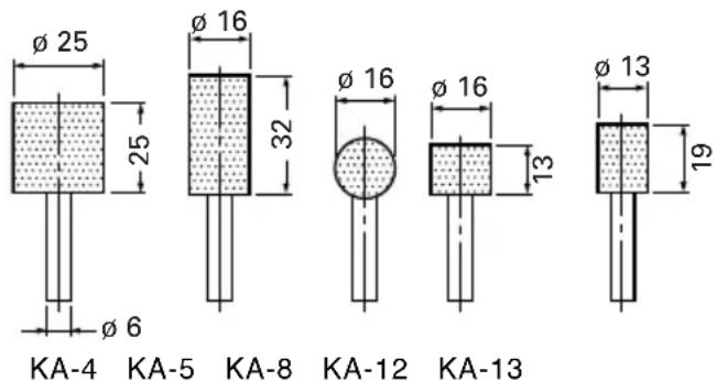
- Wheels with 3 mm shaft All wheels are provided with WA grain, 80 granding and P bonding and are suitable for grinding general and special steel materials.
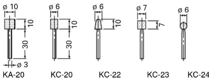
○ Dresser
Case
Optional accessories are subject to change without notice.
APPLICATIONS
○ Finishing of dies for press working, die casting and moulding.
○ Finishing of thread cutting dies, tools and other small parts.
- Internal grinding of tools and machine parts.
PRIOR TO OPERATION
- Power source Ensure that the power source to be utilized conforms to the power requirements specified on the product nameplate.
NOTE When connected to the power supply, the built-in electronic control circuit shifts to standby status and the grinder becomes slightly warm, but this is not a malfunction.
CAUTION Do not operate from a direct current power source, engine generator, booster or any other type of transformer. Doing so may not only cause damage to the grinder, but may lead to accidents.
-
Power switch Ensure that the power switch is in the OFF position. If the plug is connected to a receptacle while the power switch is in the ON position, the power tool will start operating immediately, which could cause a serious accident.
-
Extension cord When the work area is removed from the power source, use an extension cord of sufficient thickness and rated capacity. The extension cord should be kept as short as practicable.
-
RCD The use of a residual current device with a rated residual current of 30mA or less at all times is recommended.
-
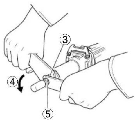
Installing a wheel Install the wheel so that length ℓ is less than 15 mm. If ℓ is longer, abnormal vibration will occur, and the machine is not only negatively affected, but there is a possibility of a serious accident. Make the ℓ as small as possible. When d = 6 mm, 6.35 mm (1/4"), 8 mm, D of the wheel should be less than the Max. wheel diam. of each models (GP3V: 25 mm, GP5V: 50 mm). If a wheel with D more than the Max. wheel diam. of each models (GP3V: 25 mm, GP5V: 50 mm) is used, the circumference speed exceeds the safety limit and the wheel will break. Never use such a wheel.
Distance L varies for D. Determine L referring to the table below.
When d = 3 mm, 3.175 mm (1/8"), D should be less than 10 mm. Determine L referring to the table below. Wheels can be simply attached and detached by using the two wrenches. (Fig. 2).
☐ Do not tighten the collet chuck by inserting a shaft thinner than the regular shaft diameter (6 mm) in the chuck or in an empty condition. This practice will damage the collet chuck.
When installing a wheel with shaft, tighten the collet chuck after applying a small quantity of spindle oil (or sewing machine oil) to the tapered portion indicated in Fig. 1.
GP3V (
when = 15mm
| d | 3 mm, 3.175 mm (1/8") | 6 mm, 6.35 mm (1/4") | 8 mm | ||||||
| D 5 | mm 6 mm 8 | mm 10 mm 1 | 3 mm 16 mm | 20 mm 25 mm | 25 mm | ||||
| L 10 | mm 13 mm | 16 mm 13 m | m 40 mm 40 | mm 25 mm | 25 mm 32 mm | ||||
GP5V (
when = 15mm
| d | 3 mm, 3.175 mm (1/8") | 6 mm, 6.35 mm (1/4") | 8 mm | ||||||||||
| D | 5 mm | 6 mm | 8 mm | 10 mm | 13 mm | 16 mm | 20 mm | 25 mm | 32 mm | 38 mm | 25 mm | 32 mm | 38 mm |
| L | 10 mm | 13 mm | 16 mm | 13 mm | 40 mm | 40 mm | 25 mm | 25 mm | 13 mm | 7 mm | 32 mm | 25 mm | 19 mm |
6. Adjusting the number of revolution
These models are equipped with an electronic infinite-variable-speed drive and can change the number of revolution according to a use.
If you turn and set the dial scale (Fig. 6) to 6, the number of revolution increases, and if you turn and set it to 1, the number of revolution decreases.
Before use, set the number of revolution using the dial. In so doing, refer to the following table as a rough guide.
| Dial | Use | Rotation speed (min-1) | |
| GP3V | GP5V | ||
| 1 | Polishing, finishing | 7000 | 2000 |
| 2 | Removal of paint or coat | 11400 3250 | |
| 3 | Removal of rust | 15800 4500 | |
| 4 | Removal of burrs | 20200 5800 | |
| 5 | Grinding | 24600 | 7050 |
| 6 | Rough grinding | 29000 | 8300 |
NOTE: Use caution not to turn the dial scale to any value below 1 or above 6.
7. Caution when using near welding equipment
When using the grinder in the immediate vicinity of welding equipment, the rotational speed may become unstable. Do not use the grinder near welding equipment.
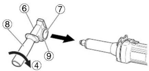
8. Using the side handle (Fig. 3)
Be sure to use the side handle to avoid the risk of severe electrical shock.
Attach the side handle to the machine as follows.
(1) Loosen the side handle grip and insert the side handle to the nose bracket part of the machine from the flange part of the side handle sleeve.
(2) Set the side handle to a position that is suited to the operation and then securely tighten the side handle grip.
HOW TO USE
1. Switching operation
(1) When moving the switch lever to the right (ON side), power is applied; when moving it to the left (OFF side), power is switched off.
(2) When first turning on the switch after installing a new wheel, hold the grinder away from your body to avoid any danger of a wheel shattering due to an imperfection.
(3) Before starting, test the machine with the wheel pointed in a safe direction.
2. Precautions on operation
(1) Lightly press the wheel to the material to be ground. When grinding materials, high-speed revolution is necessary. Use a hand grinder with high-speed revolution, minimizing the pressing force.
CAUTION
When using the tool at any value except the full speed (Dial scale 6), the motor cannot be sufficiently cooled due to the decreased number of revolution. This could result in the risk of burning and damaging the motor before an overload protective mechanism starts to function.
Make sure that you use the tool by lightly applying it to the surface of material when you use it at any value except the full speed (Dial scale 6).
(2) Dressing the wheel
After attaching a wheel, correct deflection of the wheel center by using a dresser. If the wheel center is eccentric, not only precise finishing cannot be achieved but also grinder vibration increases, lowering grinder accuracy and durability.
A clogged or worn wheel will spoil the finishing surface or lower grinding efficiency. Occasionally dress the wheel by applying the dresser.
WHEEL SELECTING METHOD
Types of wheels are varied according to the materials to be ground. Select a wheel appropriate for the material to be ground.
The following table is an outline of wheels and materials to be ground.
| Materials to be ground Grain Grading Bonding degree Structure Bonding agent | |||||
| Mild steel, hard steel, forged steel | WA | 60~80 P m V | |||
| Cast iron | C | 3 | 6 | M m | - V |
| Brass, bronze, aluminium | C | 3 | 6 | J m | - V |
| Ceramic | WA | 60~80 | M | m | V |
| Synthetic resin | C | 3 | 6 | K m | - V |
Small-scaled wheels with shaft are prepared for grinding small surfaces. Their dimensions and shapes are shown in "OPTIONAL ACCESSORIES".
Since wheel shaft diameter is 3 mm, use the collet chuck for 3 mm shaft sold separately by your HiKOKI dealer as an optional accessory.
MAINTENANCE AND INSPECTION
1. Inspecting the wheel
Ensure that the wheel is free of cracks and surface defects.
2. Inspecting the mounting screws
Regularly inspect all mounting screws and ensure that they are properly tightened. Should any of the screws be loose, retighten them immediately. Failure to do so could result in serious hazard.
3. Maintenance of the motor
The motor unit winding is the very "heart" of the power tool.
Exercise due care to ensure the winding does not become damaged and/or wet with oil or water.
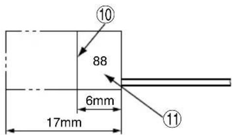
4. Inspecting the carbon brushes (Fig. 4)
The motor employs carbon brushes which are consumable parts. Since an excessively worn carbon brush can result in motor trouble, replace the carbon brushes with new ones having the same carbon brush No. shown in the figure when it becomes worn to or near the “wear limit”. In addition, always keep carbon brushes clean and ensure that they slide freely within the brush holders.
5. Replacing carbon brushes (Fig. 5)
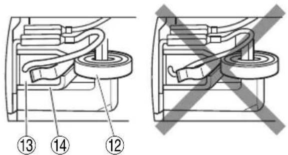
(1) Loosen the D4 tapping screw retaining the tail cover and remove the tail cover.
(2) Use the auxiliary hexagonal wrench or small screwdriver to pull up the edge of the spring that is holding down the carbon brush. Remove the edge of the spring toward the outside of the brush holder.
(3) Remove the end of the pig-tail on the carbon brush from the terminal section of brush holder and then remove the carbon brush from the brush holder.
(1) Insert the end of the pig-tail of the carbon brush in the terminal section of brush holder.
(2) Insert the carbon brush in the brush holder.
(3) Use the auxiliary hexagonal wrench or small screwdriver to return the edge of the spring to the head of the carbon brush.
NOTE
Make sure the end of the spring is not holding the pig-tail.
(4) Mount the tail cover and tighten the D4 tapping screw.
6. Replacing supply cord
If the replacement of the supply cord is necessary, it has to be done by HiKOKI Authorized Service Center to avoid a safety hazard.
7. Service parts list
CAUTION
Repair, modification and inspection of HiKOKI Power Tools must be carried out by a HiKOKI Authorized Service Center.
This Parts List will be helpful if presented with the tool to the HiKOKI Authorized Service Center when requesting repair or other maintenance.
In the operation and maintenance of power tools, the safety regulations and standards prescribed in each country must be observed.
MODIFICATIONS
HiKOKI Power Tools are constantly being improved and modified to incorporate the latest technological advancements.
Accordingly, some parts may be changed without prior notice.
GUARANTEE
We guarantee HiKOKI Power Tools in accordance with statutory/country specific regulation. This guarantee does not cover defects or damage due to misuse, abuse, or normal wear and tear. In case of complaint, please send the Power Tool, undismantled, with the GUARANTEE CERTIFICATE found at the end of this Handling instruction, to a HiKOKI Authorized Service Center.
NOTE
Due to HiKOKI's continuing program of research and development, the specifications herein are subject to change without prior notice.
IMPORTANT
Correct connection of the plug
The wires of the main lead are coloured in accordance with the following code:
Blue: - Neutral
Brown: – Live
As the colours of the wires in the main lead of this tool may not correspond with the coloured markings identifying the terminals in your plug proceed as follows:
The wire coloured blue must be connected to the terminal marked with the letter N or coloured black.
The wire coloured brown must be connected to the terminal marked with the letter L or coloured red.
Neither core must be connected to the earth terminal.
NOTE
This requirement is provided according to BRITISH STANDARD 2769: 1984.
Therefore, the letter code and colour code may not be applicable to other markets except The United Kingdom.
Information concerning airborne noise and vibration The measured values were determined according to EN60745 and declared in accordance with ISO 4871.
Measured A-weighted sound power level: 94 dB (A) Measured A-weighted sound pressure level: 83 dB (A) Uncertainty K: 3 dB (A).
Wear hearing protection.
Vibration total values (triax vector sum) determined according to EN60745.
Surface grinding: Vibration emission value a_h , SG = 4.0 m/s ^2 Uncertainty K = 1.5 m/s ^2
The declared vibration total value has been measured in accordance with a standard test method and may be used for comparing one tool with another.
It may also be used in a preliminary assessment of exposure.
WARNING
☐ The vibration emission during actual use of the power tool can differ from the declared total value depending on the ways in which the tool is used.
- Identify safety measures to protect the operator that are based on an estimation of exposure in the actual conditions of use (taking account of all parts of the operating cycle such as the times when the tool is switched off and when it is running idle in addition to the trigger time).
vour de 3,175 mm (1/8") as
vour de 6,35 mm (1/4") as
vour de 8 mm as
GP5V
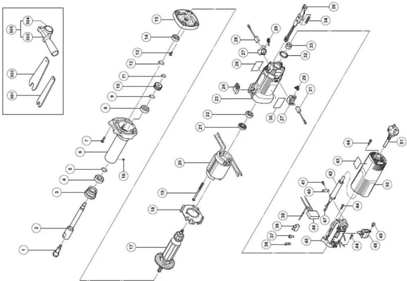
| Item No. | Part Name | Q'TY |
| 42 | CORD ARMOR | 1 |
| 43 | SETTING LABEL(B) | 1 |
| 44 | TAPPING SCREW (W/FLANGE) D4×20 | 3 |
| 45 | CONTROLLER | 1 |
| 46 | NOISE SUPPRESSOR | 1 |
| 47 | TERMINAL | 1 |
| 48 | SWITCH | 1 |
| 49 | MACHINE SCREW (W/WASHER) M3.5×6 | 2 |
| 50 | TAIL COVER | 1 |
| 51 | CORD | 1 |
| 501 | WRENCH 12MM | 1 |
| 502 | WRENCH 17MM | 1 |
| 503 | SIDE HANDLE | 1 |
| 504 | FLANGED SLEEVE | 1 |
| 505 | SIDE HANDLE SLEEVE ASS'Y | 1 |
| Item No. | Part Name | Q'TY |
| 1 COLLET CHUCK 1 | ||
| 2 S P I N D L E 1 | ||
| 3 BEARING LID (B) 1 | ||
| 4 BALL BEARING 6001VVCMPS2L 1 | ||
| 5 R I N G 1 | ||
| 6 N O S E B R A C K E T | ||
| 7 TAPPING SCREW(W/SP. WASHER) D5×30 | 4 | |
| 8 BALL BEARING 6000VVCM PS2L 1 | ||
| 9 RETAINING RING FOR D10 SHAFT 1 | ||
| 10 FIRST GEAR 1 | ||
| 11 RETAINING RING FOR D8 SHAFT 1 | ||
| 12 RETAINING RING 1 | ||
| 13 SLOTTED HD. SCREW(SEAL LOCK) M4×8 | 2 | |
| 14 BALL BEARING 609VVC2PS2L | 1 | |
| 15 INNER COVER | 1 | |
| 16 HEX. SOCKET SET SCREW M4×4 | 1 | |
| 17 ARMATURE | 1 | |
| 18 FAN GUIDE | 1 | |
| 19 HEX. HD. TAPPING SCREW D4×70 | 2 | |
| 20 STATOR | 1 | |
| 21 DUST SEAL | 1 | |
| 22 BALL BEARING 608VVC2PS2L | 1 | |
| 23 HOUSING | 1 | |
| 24 SLIDE KNOB | 1 | |
| 26 NAME PLATE | 1 | |
| 27 BRUSH HOLDER 2 | ||
| 28 CARBON BRUSH | 1 | |
| 29 SPRING | 2 | |
| 30 BRAND LABEL | 1 | |
| 31 CARBON BRUSH | 1 | |
| 32 RUBBER RING | 1 | |
| 33 MAGNET | 1 | |
| 34 SPRING | 1 | |
| 35 SLIDE BAR | 1 | |
| 36 TERMINAL M4.0 (10 PCS.) | 1 | |
| 37 CONNECTOR 50091(10 PCS.) | 1 | |
| 38 PILLAR TERMINAL | 1 | |
| 39 EARTH TERMINAL | 1 | |
| 40 CORD CLIP | 1 | |
| 41 TAPPING SCREW(W/FLANGE) D4×16 | 2 | |
natural_image
Line drawing of a quill pen in an inkwell (no text or symbols)| English Nederlands | |
| GUARANTEE CERTIFICATE1 Model No.2 Serial No.3 Date of Purchase4 Customer Name and Address5 Dealer Name and Address(Please stamp dealer name and address) | GARANTIEBEWIJS1 Modelnummer2 Serienummer3 Datum van aankoop4 Naam en adres van de gebruiker5 Naam en adres van de handelaar(Stempel a.u.b. naam en adres vande de handelaar) |
| Deutsch Español | |
| GARANTIESCHEIN1 Modell-Nr.2 Serien-Nr.3 Kaufdaturn4 Name und Anschrift des Kunden5 Name und Anschrift des Händlers(Bitte mit Namen und Anschrift des Handlers abstempeln) | CERTIFICADO DE GARANTÍA1 Número de modelo2 Número de serie3 Fecha de adquisición4 Nombre y dirección del cliente5 Nombre y dirección del distribudor(Se ruega poner el sello del distribudor con su nombre y dirección) |
| Français Português | |
| CERTIFICAT DE GARANTIE1 No. de modèle2 No de série3 Date d'achat4 Nom et adresse du client5 Nom et adresse du revendeur(Cachet portant le nom et l'adresse du revendeur) | CERTIFICADO DE GARANTIA1 Número do modelo2 Número do série3 Data de compra4 Nome e morada do cliente5 Nome e morada do distribuidor(Por favor, carímbe o nome e morada do distribuidor) |
| Italiano | |
| CERTIFICATO DI GARANZIA1 Modello2 N° di serie3 Data di acquisto4 Nome e indirizzo dell'acquirente5 Nome e indirizzo del rivenditore(Si prega di apporre il timbro con questi dati) |
HiKOKI
| 1 | |
| 2 | |
| 3 | |
| 4 | |
| 5 |
Siemensring 34, 47877 willich, Germany
Tel: +49 2154 49930
Fax: +49 2154 499350
URL: http://www.hikoki-powertools.de
Hikoki Power Tools Netherlands B.V.
Brabanthaven 11, 3433 PJ Nieuwegein, The Netherlands
Tel: +31 30 6084040
Fax: +31 30 6067266
URL: http://www.hikoki-powertools.nl
Hikoki Power Tools (U.K.) Ltd.
Precedent Drive, Rooksley, Milton Keynes, MK 13, 8PJ, United Kingdom
Tel: +44 1908 660663
Fax: +44 1908 606642
URL: http://www.hikoki-powertools.uk
Hikoki Power Tools France S.A.S.
Hikoki Power Tools Belgium N.V./S.A.
Koningin Astridlaan 51, B-1780 Wemmel, Belgium
Tel: +32 2 460 1720
Fax: +32 2 460 2542
URL http://www.hikoki-powertools.be
Hikoki Power Tools Italia S.p.A
Via Piave 35, 36077, Altavilla Vicentina (VI), Italy
Tel: +39 0444 548111
Fax: +39 0444 548110
URL: http://www.hikoki-powertools.it
Hikoki Power Tools Ibérica, S.A.
C/ Puigbarral, 26-28, Pol. Ind. Can Petit, 08227 Terrassa
(Barcelona), Spain
Tel: +34 93 735 6722
Fax: +34 93 735 7442
URL: http://www.hikoki-powertools.es
natural_image
Line drawing of a quill pen with inkwell, no text or symbols present
natural_image
Line drawing of a quill pen with inkwell, no text or symbols present| English Nederlands | ||
| EC DECLARATION OF CONFORMITYWe declare under our sole responsibility that Electronic Hand Grinder, identified by type and specific identification code *1), is in conformity with all relevant requirements of the directives *2) and standards *3). Technical fi le at *4) – See below.The European Standard Manager at the representative office in Europe is authorized to compile the technical fi le.The declaration is applicable to the product affi xed CE marking. | EC VERKLARING VAN CONFORMITEITWij verklaren onder onze eigen verantwoordelijkheid dat Electronische rechte slipper, geidentificeerd door het type en de specifieke identificatiecode *1), voldoet aan alle relevante vereisten van de richtlijnen *2) en normen *3). Technische documentatie bij*4) – zie onder.De Europese Normen Manager bij de vertegenwoordiging in Europa is gemachtigd om het technisch dossier samen te stellen.Deze verklaring is van toepassing op producten voorzien van de CE-markeringen. | |
| Deutsch Español | ||
| EG-KONFORMITÄTSERKLÄRUNGWir erklären in alleiniger Verantwortung, dass der durch den Typ und den spezifischen Identifizierungscode *1) identifizierte Elektronik Geradschleifer allen einschlägigen Bestimmungen der Richtlinien *2) und Normen *3) entspricht. Technische Unterlagen unter *4) – Siehe unten.Die Leitung der repräsentativen Behörde für europäische Normen und Richtlinien ist berechtigt, die technischen Unterlagen zusammenzustellen.Die Erklärung gilt für die an dem Produkt angebrachte CE-Kennzeichnung. | DECLARACIÓN DE CONFORMIDAD DE LA CEDeclaramos bajo nuestra única responsabilidad que la Amoladora recta electrónica, identificada por tipo y por código de identificación específico *1), está en conformidad con todas las disposiciones correspondientes de las directivas *2) y de las normas *3). Documentación técnica en *4) – Ver a continuación.El Director de Normas Europeas en la oficina de representación en Europa está autorizado para elaborar el expediente técnico.La declaración se aplica al producto con marcas de la CE. | |
| Français Português | ||
| DECLARATION DE CONFORMITE CENous déclarons sous notre entière responsabilité que la Meuleuse droite electronique, identifiée par le type et le code d'identification spécifique *1) est en conformité avec toutes les exigences applicables des directives *2) et des normes *3). Dossier technique en *4) - Voir ci-dessous.Le Gestionnaire des normes européennes du bureau de représentation en Europe est autorisé à constituer le dossier technique.Cette déclaration s'applique aux produits désignés CE. | DECLARAÇÃO DE CONFORMIDADE CEDeclaramos, sob nossa única e inteira responsabilidade, que Rectificadora Recta Eletrónica, identificada por tipo e código de identificação específico *1), está em conformidade com todos os requerimentos relevantes das diretivas *2) e normas *3). Ficheiro técnico em *4)–Consulte abaixo.O Gestor de Normas Europeias no escritório de representação na Europa está autorizado a compilar o fi cheiro técnico.A declaração aplica-se aos produtos com marca CE. | |
| Italiano | ||
| DICHIARAZIONE DI CONFORMITÀ CEDichiariamo sotto la nostra esclusiva responsabilità che la smerigliatrice elettronica a mano, identificata dal tipo e dal codice identificativo específico *1), è conforme a tutti i requisiti delle direttive *2) e degli standard *3). Documentazione tecnica presso *4) – Vedere sotto.Il gestore delle norme europee presso l'ufficio di rappresentanza in Europa è autorizzato a compilare il fascicolo tecnico.La dichiarazione è applicabile ai prodotti cui sono applicati i marchi CE. | ||
| *1) GP3V C342715R C342717MGP5V C342716R C342718M*2) 2006/42/EC, 2014/30/EU, 2011/65/EU*3) EN60745-1:2009+A11:2010EN60745-2-3:2011+A2:2013+A11:2014+A12:2014+A13:2015EN55014-1:2006+A1:2009+A2:2011EN55014-2:1997+A1:2001+A2:2008EN61000-3-2:2014EN61000-3-3:2013 | ||
| *4) Representative office in EuropeHikoki Power Tools Deutschland GmbHSiemensring 34, 47877 Willich, GermanyHead office in JapanKoki Holdings Co., Ltd.Shinagawa Intercity Tower A, 15-1, Konan 2-chome, Minato-ku, Tokyo, Japan | 29. 6. 2018Naoto YamashiroEuropean Standard Manager29. 6. 2018A. NakagawaCorporate Officer | |
Koki Holdings Co., Ltd.


- GENERAL POWER TOOL SAFETY WARNINGS
- WARNING
- Save all warnings and instructions for future reference.
- 1) Work area safety
- 2) Electrical safety
- 3) Personal safety
- 4) Power tool use and care
- 5) Service
- PRECAUTION
- SAFETY WARNINGS COMMON FOR GRINDING OPERATIONS
- KICKBACK AND RELATED WARNINGS
- SAFETY WARNINGS SPECIFIC FOR GRINDING OPERATIONS
- GENERAL SAFETY INSTRUCTIONS FOR GRINDERS
- Electronic Control
- NOTE
- STANDARD ACCESSORIES
- OPTIONAL ACCESSORIES (sold separately)
- APPLICATIONS
- PRIOR TO OPERATION
- Adjusting the number of revolution
- Caution when using near welding equipment
- Using the side handle (Fig. 3)
- HOW TO USE
- Switching operation
- Precautions on operation
- CAUTION
- Dressing the wheel
- WHEEL SELECTING METHOD
- MAINTENANCE AND INSPECTION
- Inspecting the wheel
- Inspecting the mounting screws
- Maintenance of the motor
- Inspecting the carbon brushes (Fig. 4)
- Replacing carbon brushes (Fig. 5)
- Replacing supply cord
- Service parts list
- MODIFICATIONS
- GUARANTEE
- IMPORTANT
- Correct connection of the plug
- Hikoki Power Tools Netherlands B.V.
- Hikoki Power Tools (U.K.) Ltd.
- Hikoki Power Tools France S.A.S.
- Hikoki Power Tools Belgium N.V./S.A.
- Hikoki Power Tools Italia S.p.A
- Hikoki Power Tools Ibérica, S.A.
- Koki Holdings Co., Ltd.
Brand : HiKOKI
Model : GP5V
Category : Sander