AquaMax Eco Classic 9000 C - Water pump OASE - Free user manual and instructions
Find the device manual for free AquaMax Eco Classic 9000 C OASE in PDF.

| Product Type | Pond Water Pump |
| Model | AquaMax Eco Classic 9000 C |
| Brand | OASE |
| Connection Voltage | 220-240 V AC |
| Frequency | 50/60 Hz |
| Power Consumption | 23 to 90 W |
| Protection Rating (pump) | IP68 (waterproof up to 4 m) |
| Protection Rating (controller) | IP44 |
| Max. Delivery Capacity | 8,800 l/h |
| Max. Delivery Head | 4.5 m |
| Max. Immersion Depth | 4 m |
| Max. Particle Diameter | 8 mm |
| Pump Cable Length | 10 m |
| Controller Cable Length | 2 m |
| Dimensions (L × W × H) | 280 × 230 × 140 mm |
| Weight | 4.4 kg |
| Permissible Water Temperature | +4 to +35 °C |
| Permissible pH | 6.8 - 8.5 |
| Permissible Hardness | 8 - 15 °dH |
| Main Functions | Filtration pump, controller with speed adjustment, Easy Switch app, EFC self-test |
| Maintenance and Cleaning | Clean 2 times per year with clear water or PumpClean product |
| Safety | 30 mA residual current circuit breaker recommended, do not use in natural swimming pool, do not run dry |
| Wear Parts | Functional unit (replaceable) |
| Recycling | Do not dispose of with household waste, return to recycling center |
Frequently Asked Questions - AquaMax Eco Classic 9000 C OASE
User questions about AquaMax Eco Classic 9000 C OASE
0 question about this device. Answer the ones you know or ask your own.
Ask a new question about this device
Download the instructions for your Water pump in PDF format for free! Find your manual AquaMax Eco Classic 9000 C - OASE and take your electronic device back in hand. On this page are published all the documents necessary for the use of your device. AquaMax Eco Classic 9000 C by OASE.
USER MANUAL AquaMax Eco Classic 9000 C OASE
natural_image
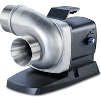
Exterior view of a black Oase water purifier with a blue plastic bulb and control panel (no text or symbols visible)AquaMax Eco Classic
EN Operating instructions
FR Notice d'emploi
natural_image
Diagram of a mechanical device with fluid flow and directional arrows, no text or symbols present
AMX0206
natural_image
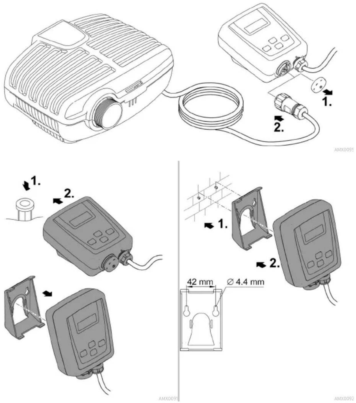
Line drawing of a portable projector connected to a digital device via cable (no text or symbols)AMX0095

AMX0092
HINWEIS
Environmental Function Control (EFC)
natural_image
Exploded view diagram of a mechanical assembly showing internal components and a 4x scale indicator (no text or labels)AMX0093
Lagern/Überwintern
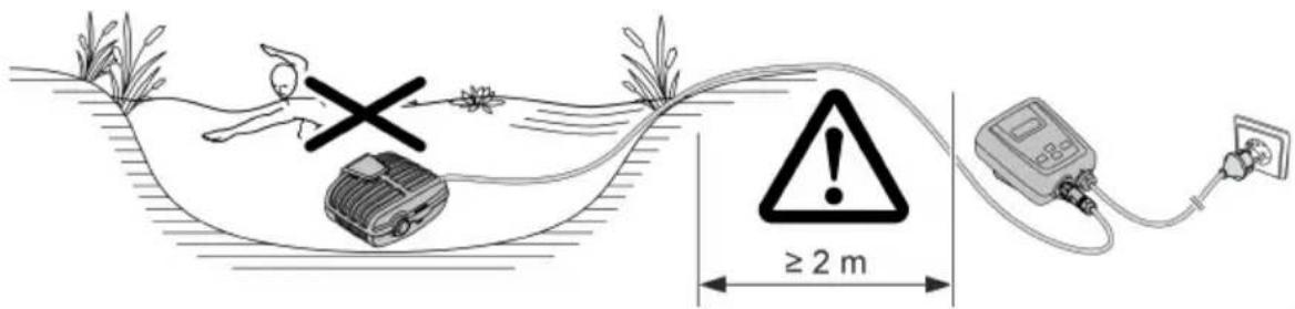
▶ Disconnect all electrical devices in the water from the power supply before reaching into the water. Otherwise there is a risk of severe injuries or death by electrocution.
This unit can be used by children aged 8 and above and by persons with reduced physical, sensory or mental capabilities or lack of experience and knowledge if they are supervised or have been instructed on how to use the unit in a safe way and they understand the hazards involved. Do not allow children to play with the unit. Only allow children to carry out cleaning and user maintenance under supervision.
Safety information
Electrical connection
- Special regulations apply for electrical installation in outdoor spaces. Only a qualified electrician may perform the electrical installation.
- The qualified electrician has the necessary professional training, knowledge and experience to perform electrical installation in outdoor spaces. The electrician can detect potential dangers and knows how to adhere to regional and national standards, regulations and directives.
— For your own safety, please consult a qualified electrician.
- Only connect the unit if the electrical data of the unit and the power supply match.
- Only plug the unit into a correctly installed outlet.
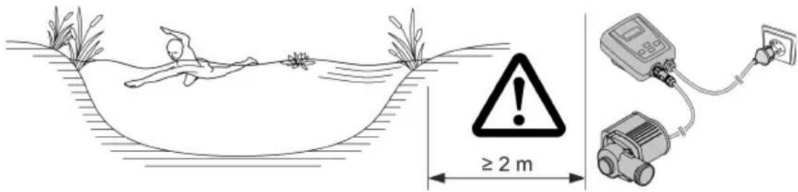
- The device is to be supplied through a residual current device (RCD) having a rated residual operating current not exceeding 30 mA.
- Extension cables and power distributors (e.g. outlet strips) must be suitable for outdoor use (splash-proof).
- Protect open plugs and sockets from moisture.
Safe operation
- Do not use the unit, if electrical lines or the housing are damaged.
- Dispose of the unit if its power connection cable is damaged. The power connection cable cannot be replaced.
- The impeller unit in the pump contains a magnet with a strong magnetic field that may affect the operation of pacemakers or implantable cardioverter defibrillators (ICDs). Keep a distance of at least 0.2 m between the implant and the magnet.
- Do not carry or pull the unit by its power cable.
- Route lines in such a way that they are protected from damage and do not present a tripping hazard.
- Never carry out technical changes to the unit.
- Only carry out work on the unit that is described in this manual.
- Only use original spare parts and accessories.
- Should problems occur, please contact the authorised customer service or OASE.
Intended use
Only use the product described in this manual as follows:
- For pumping normal pond water for filter systems, waterfall systems and water course systems.
- While adhering to the technical specifications. (→ Technical data)
- Adherence to the permissible water quality. (→ Permissible water quality)
The following restrictions apply to the unit:
- Do not use in swimming ponds.
- Never use the unit with fluids other than water.
- Never run the unit without water.
- Do not use in conjunction with chemicals, foodstuff, easily flammable or explosive substances.
- Do not connect to the domestic water supply.
- Do not use for commercial or industrial purposes.
- According to EMC (Electromagnetic Compatibility), this is a class A unit. The unit may cause malfunctions in living environments. It is the user's responsibility to take suitable counter-measures.
Product Description Overview
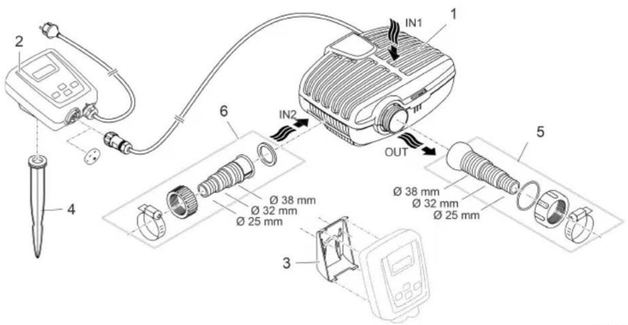
A Description
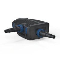
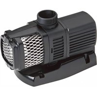
| 1 | Filter pump |
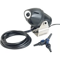
| 2 | Controller for regulating the speed of the filter pumpControl via the OASE App "Easy Switch" |
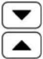
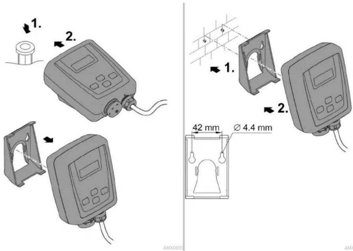
| 3 | Retaining frame for mounting controller to the wall |
| 4 | Ground stake for mounting controller at ground level |
| 5 | Stepped hose adapter with ball joint, seal, coupling nut and hose clip |
| 6 | Stepped hose adapter with coupling nut and hose clip |
Symbols on the unit
| IP68 4.0 m | Dust tight. Watertight to a depth of 4 m. |
| IP44 | Dust protected. Protected against water splashed from all directions.Do not immerse. |
 | Remove the unit at temperatures below zero (centigrade). |
 | Possible danger for persons with pacemakers. |
 | Protect from direct sunlight. |
 | Do not dispose of with household waste. |
 | Read the instructions for use. |
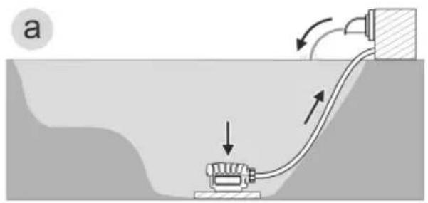
Installation variants
natural_image
Diagram of a mechanical device submerged in a liquid channel with directional arrows indicating flow or movement (no text or symbols)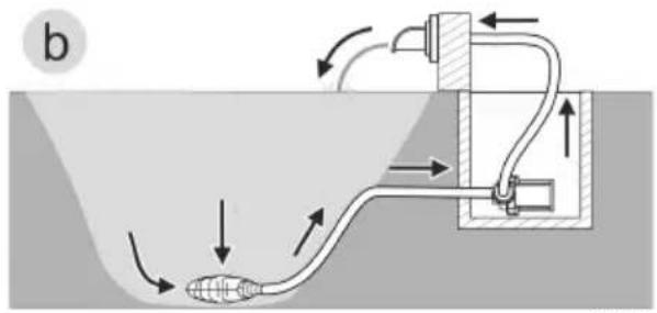
natural_image
Diagram of a fluid system with pipe flow and valve components (no text or labels)- Variant (a): Submerged pump installation
— The pump is positioned in the pond or basin.
— Water flow via the filter cage.
- Variant (b): Dry pump installation
- The pump is installed without the filter cage outside of the pond or basin but lower than the water level.
— Water flow via a satellite filter or skimmer.
Installation and connection
The pump can be installed submerged (in water) or dry (outside the water).
WARNING
Severe injuries or death due to operation of this unit in a swimming pond. Defective electrical components will electrify the water with dangerous electrical voltage.
▶ Never operate the unit in a swimming pond.
CAUTION
Rotating components in the intake and pressure socket area. Risk of injury when reaching into the sockets.
In particular, observe the following: A unit that has stopped due to overload can start up unexpectedly!
▶ Do not reach into the opening of the intake socket or pressure socket while the power plug is plugged in.
▶ If the sockets are freely accessible during operation, e.g. if no hoses are connected, use a hand guard to secure the sockets. The hand guard is available as an accessory.
Avoid exposing any unit components to direct sunlight for extended periods of time, as this can lead to damage. If necessary, use a protective cover.
Submerged installation of the pump
Connecting
AMX0206
Do not plug the power plug into the socket yet!
Installation
- Place the pump horizontally on a stable surface.
- Ensure secure and stable positioning of the pump.
- For muddy or soiled water, we recommend installing the pump or intake-side components (skimmer, satellite filter, base outlet, etc.) above ground level. This decreases intake of particles and increases the service life of the impeller unit.
- Only operate the pump when it is covered in at least 10 cm of water. Otherwise it may draw in air.
AMX009C
The pull rope allows you to simply pull the pump from the water.
- Fasten the pull rope on the bottom filter casing through the round openings and make a knot.
Install the unit at a dry place
Dry installation requires the pump to be installed without a filter housing.
Conversion
EN
AMX0204
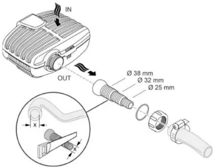
Connecting
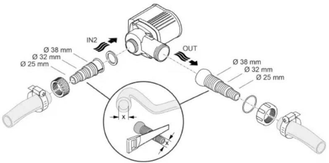
- Hoses or pipes can be connected to the inlet (IN) and outlet (OUT).
- Connections for hoses are part of the scope of delivery. Instructions for their installation can be found below.
— An adapter for pipes with DN75/DN110 is available as an accessory (article number 35578). - Ensure that the intake-side hose (IN) does not have a smaller diameter than the pressure-side hose (OUT).
- The larger the hose diameter, the smaller the friction losses in the lines and the better the flow rate.
- The hose diameter must not be limited unnecessarily by a hose sleeve. Shorten the hose sleeve based on the hose diameter, if necessary.
AMX0094
Do not plug the power plug into the socket yet!
Installation
- Place the pump horizontally on a stable surface.
- Ensure secure and stable positioning of the pump.
- Do not expose the pump to direct sunlight.
- Ensure that the installation site is sufficiently ventilated to prevent overheating of the pump. Permissible ambient temperatures (→ Technical data)
AMX0085
Connecting the controller
Commissioning/start-up
NOTE
The unit will be destroyed if it is operated with a dimmer. It contains sensitive electrical components.
▶ Do not connect the unit to a dimmable power supply.
NOTE
Never allow the pump to run dry. Otherwise the pump may be destroyed.
▶ Only operate the pump when it is submerged or flooded.
Switching ON/OFF
Switching on
The pump must be connected to the controller before the controller is switched on.
- First connect the controller to the mains supply, then switch on the pump at the controller.
Switching off
- Switch the pump off at the controller.
- Disconnect the controller from the mains before performing any work on the unit.
Environmental Function Control (EFC)
When started up and then every 20 ... 40 minutes the pump automatically performs a pre-programmed self-test (Environmental Function Control (EFC)). The pump detects if it is running dry / clogged or submerged. The pump shuts down automatically after 60 to 120 seconds if it runs dry/is blocked. In the event of a malfunction, disconnect the power supply and “flood the pump” or remove the obstacle. Afterwards, the unit can be restarted.
Operation
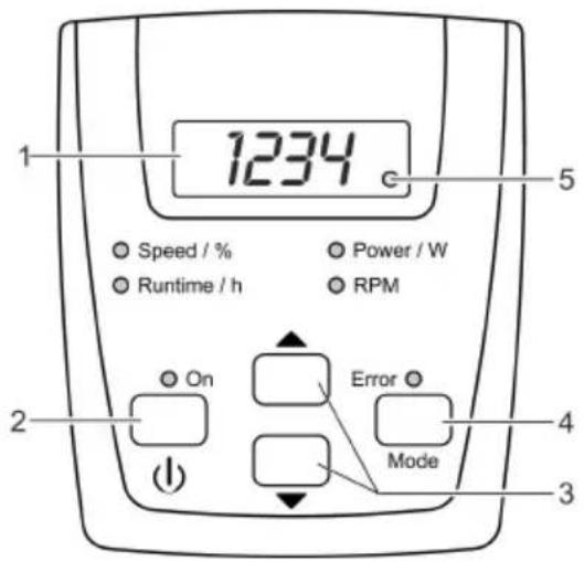
Controller overview
EN

AMX0087
| Description | Function | |
| 1 | Four-digit LED display | For displaying valuesStandard display is "Power / W" mode. |
| 2 | "On/Off" button | For switching the pump on or off |
| 3 | Arrow keys | For increasing or decreasing rotation speed/power output |
| 4 | "Mode" button | For selecting the next modeFor switching the wireless connection on/off |
| 5 | LED wireless connection | The LED lights up when the wireless connection is switched on.The LED blinks when connected to the OASE App. |
| C | Speed / %Runtime / hPower / W RPM | The respective LED lights up for the mode that is selected.The current mode appears in the display. |
| C | ON | The LED lights up when the pump is switched on. |
| C | Error | The LED lights up when an error occurs.The error code appears in the display. |
Operating functions
Switching the pump on/off
| Proceed as follows | Information | |
| Press the button briefly to turn the pump on or off. | When the pump is switched off, the display shows "OFF". | |
Increasing or decreasing rotation speed
| Proceed as follows | Information | |
 | Press the desired button several times or push continually in order to change the rotation speed in per-cent. | Adjustable range: 1% ... 100 %Increment: 1 %Adjustment is only possible in "Speed / %" or "Power / W" modes. |
- The adjusted value is immediately adopted.
- By pressing a button the controller automatically switches to "Speed / %" mode.
After 15 s without operation the controller automatically switches to "Power / W" mode.
Displaying current status values
| Proceed as follows | Information | |
 | Press the button briefly to select the "Runtime / h" mode next mode. | Displays the total operating hours of the pump |
"Runtime / h" mode
- Displays the total operating hours of the pump
• Displays up to 9999 operating hours: 0 to 9999
– Displayed increments: 1 hour
- Displays from 10000 to 99900 operating hours: 100H to 999H
– Displayed increments: 100 hours
- Example: 0224 = 22 × 100 = 2200 operating hours
"Power / W" mode
- Displays the current power consumption of the pump in watts
- Tolerance: ±5 % of the max. power consumption. (→ Technical data)
"RPM" mode
- Displays the current speed of the pump in revolutions per minute
"Speed / %" mode
- Displays the current speed in percentage – Display range: 1 to 100
After 15 s without operation the controller automatically switches to "Power / W" mode.
Switching the wireless connection on/off
Proceed as follows
Information
MODE
Press and hold the button for longer than 10 s.
- If bOF appears in the display, the wireless connection is switched off.
- If b0n appears in the display, the wireless connection is switched on.
- The LED in the display lights up when the wireless connection is switched on.
- The LED in the display blinks when connected to the OASE App.
- (→ Controller overview)
- When the unit is delivered, the wireless connection is switched on.
After 15 s without operation the controller automatically switches to "Power / W" mode.
Connecting the controller to the smart phone/tablet
The maximum distance for interference-free communication between the controller and smartphone/tablet depends on the transmission power of the smartphone/tablet. Brick walls, walls made of reinforced concrete, large metal objects or bushes and trees can dampen radio waves and decrease the distance.
Proceed as follows
Information
| 1. | Download and install the OASE App "Easy Switch" The OASE App is available on iOS (App Store) and An-to the smartphone/tablet. | Android (Play Store). |
| 2. | If you have not already done so, switch on the wireless connection at the controller. | (→ Switching the wireless connection on/off) |
| 3. | Activate the Bluetooth feature on the smartphone/tablet. | - |
| 4. | Start the App "Easy Switch". | After a brief search, a list of available products will appear. |
| 5. | Select your pump from the list. | An authentication code will be displayed on the con-troller for two minutes. |
| 6. | Enter the authentication code in the smartphone/tablet. | Upon successful connection, the display will change to the operating instruction page for the pump.Now, the pump can be controlled via the smartphone/tablet.The LED in the controller display blinks.(→ Controller overview) |
Maintenance and cleaning

CAUTION
Risk of injury due to unexpected start-up. Internal monitoring functions may switch off the unit and automatically reactivate it.
▶ Disconnect the power plug before carrying out any work on the unit.
NOTE
Do not use aggressive cleaning agents or chemical solutions. These agents can damage the housing, impair the function of the device and harm animals, plants and the environment.
▶ If possible, clean the unit with clear water and a soft brush or a sponge; remove stubborn dirt with the aid of the recommended cleaning agents.
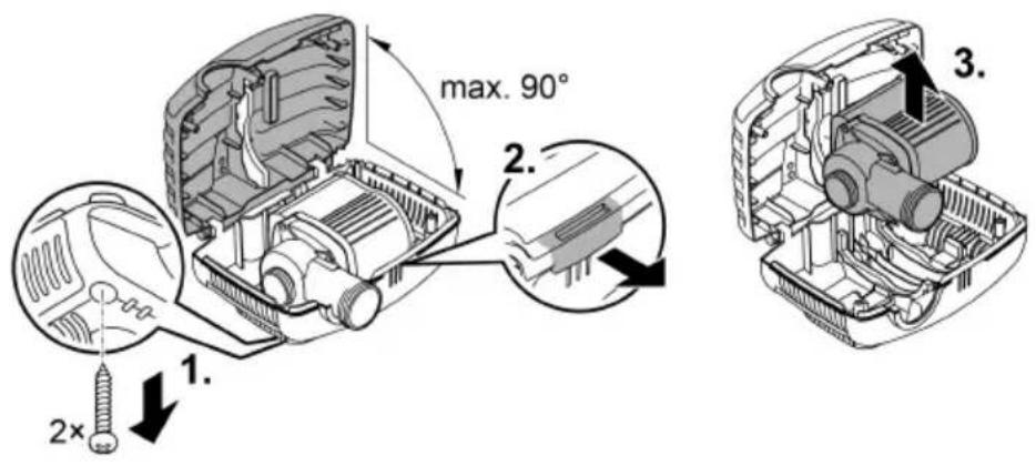
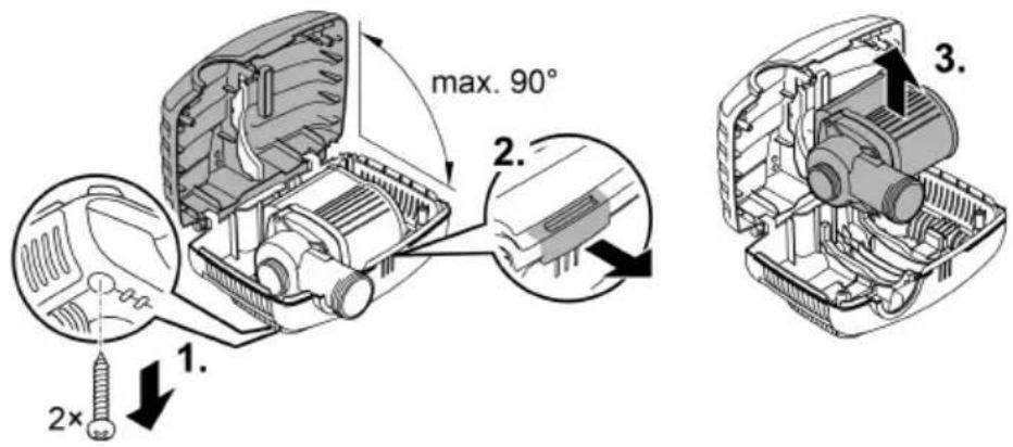
Dismantling the unit
- Pull the power plug and remove all connections.
- Dismantle the unit as shown in the figure.
AMX0204
- Reassemble the unit in reverse order.
• During assembly check that - the pump is fastened in the holder.
- the power cable is guided out through the groove on the housing and is not significantly kinked or pinched.
Cleaning the device
Clean the unit as required but at least twice per year. - When cleaning the pump, pay particular attention to the impeller unit and the pump housing.
- Recommended cleaning agent for removing stubborn limescale deposits:
- Pump cleaning agent PumpClean from OASE.
— Vinegar- and chlorine-free household cleaning agent.
• After cleaning, thoroughly rinse all parts in clean water.
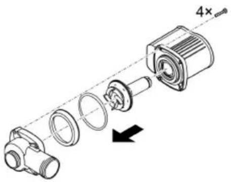
Replacing the impeller unit
NOTE
The impeller unit contains strong magnets that attract magnetic particles (e.g. iron filings). Any remaining particles can cause irreparable damage to the impeller unit and motor block.
▶ Carefully remove any adhering particles from the impeller unit prior to installation.
- Dismantle the motor block as shown in the figure.
- Use a brush under clear water to clean the components.
- Check all components for damage. Replace damaged or worn components.
- Reassemble the motor block in reverse order.
natural_image
Mechanical assembly diagram showing a shaft and housing with a 4x multiplier indicator (no text or symbols present)AMX0093
Storage/winter protection
Shut down the unit at water temperatures below +4 °C or at the latest when freezing temperatures are expected.
• Thoroughly clean the unit.
- Check the unit for damage and replace damaged components.
- Store the pump immersed in water or filled with water in an environment protected against freezing. Do not immerse the power plug in water!
Malfunction remedy Troubleshooting overview
| Malfunction | Cause | Remedy |
| Pump does not start | No mains voltage | Check the mains voltage.Check supply lines. |
| Faulty connection between pump and controller | Check connection, and if needed reconnect | |
| Pump not switched on | Switch the pump on at the controller | |
| Pump does not transport fluid | Filter housing clogged | Clean strainer casings |
| Excessively soiled water | Clean the pump. The pump automatically switches on again once the motor has cooled down. | |
| Pump is set too low | Increase the rotation speed of the pump at the controller | |
| The impeller unit is blocked | Disconnect the power supply and remove obstacle. Then switch the pump on again. | |
| Insufficient delivered quantity | Filter housing clogged | Clean strainer casings |
| Excessive loss in the supply lines | Select larger hose diameterAdjust stepped hose adapter to hose diameterReduce hose length to minimum necessaryAvoid unnecessary connection elements | |
| Pump is set too low | Increase the rotation speed of the pump at the controller | |
| Pump switches off after operating briefly | Excessively soiled water | Clean the pump. The pump automatically switches on again once the motor has cooled down. |
| The impeller unit is blocked | Disconnect the power supply and remove obstacle. Then switch the pump on again. | |
| Pump has run dry. | Flood the pump. Fully submerge the pump for operation in the pond. |
Error messages
The error message automatically disappears after the error has been corrected.
| Error message | Cause | Remedy |
| Er1 | No pump connected or connection to pump is faulty | Check that cable is connected correctly to pumpConnect the pump to the controller |
| Er2 | Communication error between controller and pump | Check that cable is connected correctly to pump.Connect the pump to the controller |
| Er3 | Excess temperature | Check that impeller unit moves freely- If the impeller unit is sluggish, the pump is requiring too much powerThe ambient temperature is too high |
| Er4 | Overcurrent | Check that impeller unit moves freelyIf the impeller unit is sluggish, the pump is requiring too much power |
| Er5 | Pump blocked | Check pump and remove obstacle |
| Er6 | Pump has run dry | Submerge pump in waterFor dry installation ensure adequate water supply |
| Er7 | Overvoltage | Connect the pump to the correct mains voltageThe unit is not suitable for use with the existing mains voltage range |
| Er8 | Undervoltage | Keep extension cable to the pump as short as possible.- The voltage to the pump is too low due to the voltage drop in long cables.Use extension cable to the pump with greater conductor cross-section- The voltage to the pump is too low due to the voltage drop in cables with too small of a conductor cross-section. |
EN
Technical data
| Description | AquaMax Eco Classic | ||||
| 9000°C | 12000°C | 18000°C | |||
| Connection voltage | V AC | 220 ... 240 | 220 ... 240 | 220 ... 240 | |
| Mains frequency | Hz | 50/60 | 50/60 | 50/60 | |
| Power consumption | W | 23 ... 90 | 26 ... 120 | 33 ... 175 | |
| Pump protection type | IP 68 | IP 68 | IP 68 | ||
| Controller protection type | IP 44 | IP 44 | IP 44 | ||
| Connection | Discharge port | G 112 G2 | G2 | ||
| Inlet port | G 112 G 112 G 112 | ||||
| Hose | mm | 25/32/38 | 25/32/38 | 25/32/38 | |
| Max. pump capacity | l/h | 8800 | 12000 | 17600 | |
| Max. pump head | m | 4.5 | 4.7 | 5.3 | |
| Filter supply surface area | cm ^2 | 810 | 810 | 810 | |
| Max. particle size, coarse dirt particles | mm 8 8 8 | ||||
| Max. immersion depth m | 4 | 4 | 4 | ||
| Length of mains cable to con-troller | m | 2 2 | 2 | ||
| Length of mains cable to pump | m | 10 | 10 | 10 | |
| Dimensions | Length | mm | 280 | 280 | 280 |
| Width | mm | 230 | 230 | 230 | |
| Height | mm | 140 | 140 | 140 | |
| Weight | kg | 4.4 | 5.0 | 5.35 | |
Permissible water quality
| Fresh water, pond water | ||
| pH value | 6.8 ... 8.5 | |
| Hardness | °dH | 8 ... 15 |
| Free chlorine | mg/l | <0.3 |
| Chloride content | mg/l | <250 |
| Salt content | % | <0.4 |
| Overall dry residue | mg/l | <50 |
| Temperature | °C | +4 ... +35 |
Wear parts
- Impeller unit
EN
Disposal
NOTE
Do not dispose of this unit with household waste.
▶ Dispose of the unit by using the return system provided for this purpose.
▶ Should you have questions, please contact your local disposal company. They will give you information on how to correctly dispose of the unit.
▶ Render the unit unusable by cutting the cables.

AVERTISSEMENT
natural_image
Diagram of a mechanical device with fluid flow and directional arrows, no text or symbols present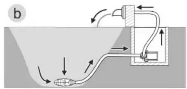
FR
AMX0206
natural_image
Line drawing of a portable projector connected to a digital device via cable (no text or symbols)AMX0095

AMX0092
Mise en service
REMARQUE
Environmental Function Control (EFC)
Mode "Puissance / W"
AMX0093
natural_image
Diagram of a mechanical device with fluid flow and directional arrows, no text or symbols present
natural_image
Diagram of a fluid system with pipe flow and valve components (no text or labels)- Variant (a): Pomp ondergedompeld opstellen
AMX0206
Environmental Function Control (EFC)
natural_image
Mechanical assembly diagram showing a disassembled motor with housing and gear components (no text or labels)AMX0093
Opslag/overwinteren
natural_image
Diagram of a mechanical device with fluid flow and directional arrows, no text or symbols present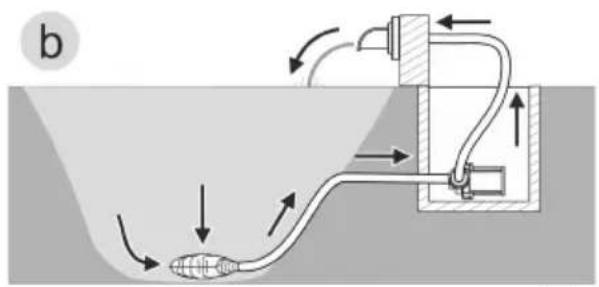
ES
AMX0206
Environmental Function Control (EFC)
natural_image
Exploded view diagram of a mechanical assembly showing internal components and a 4x scale indicator (no text or labels)AMX0093
natural_image
Diagram of a mechanical device with fluid flow and directional arrows, no text or symbols present
- Variante (a): Posicionamento da bomba dentro do tanque
— A bomba deve ser posicionada no tanque ou na piscina.
AMX0206
natural_image
Line drawing of an electronic device connected to a cable and a digital display unit (no text or symbols present)PT

Environmental Function Control (EFC)
natural_image
Exploded view diagram of a mechanical assembly showing internal components and a 4x scale indicator (no text or labels)AMX0093
Armazenar/Invernar
natural_image
Diagram of a mechanical device with fluid flow and directional arrows, no text or symbols present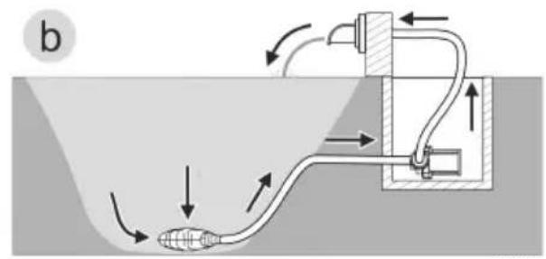
IT
AMX0206
Environmental Function Control (EFC)
natural_image
Exploded view diagram of a mechanical assembly showing internal components and a 4x magnified section (no text or labels)AMX0093
natural_image
Diagram of a mechanical device with fluid flow and directional arrows, no text or symbols present
AMX0206
natural_image
Line drawing of a portable projector connected to a digital device via cable, with two labeled parts (1 and 2) showing connection details.AMX0095

Ibrugtagning
BEMÆRK
Environmental Function Control (EFC)
natural_image
Exploded view diagram of a mechanical assembly showing internal components and a 4x magnified view (no text or labels)Opbevaring/overvintring
natural_image
Diagram of a mechanical device submerged in a liquid channel with directional arrows indicating flow or movement (no text or symbols)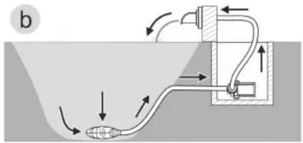
- Variant (a): Plassere pumpe nedsenket
— Pumpen plasseres i dammen eller bekken.
– Vanninntak via filterkurven. - Variant (b): Plassere pumpe tört
- Pumpen plasseres uten filterkurv utenfor dammen eller bekken, men under vannoverflaten.
— Vanninntak via et satellittfilter eller skimmer.
AMX0206
Environmental Function Control (EFC)
natural_image
Mechanical assembly diagram showing a disassembled component with a 4x magnified view (no text or labels)AMX0093
Lagring/overvintring
Apparatet må tas ut av drift ved vanntemperaturer under +4 °C eller senest när det er meldt frost.
natural_image
Diagram of a mechanical device with fluid flow and directional arrows, no text or symbols present
- Variant (a): Installera pumpen nedsänkt
— Pumpen placeras i dammen resp. bassängen.
– Vattenflöde via filterkorgen.
- Variant (b): Installera pumpen torrt
AMX0206
Environmental Function Control (EFC)
natural_image
Exploded view diagram of a mechanical assembly showing internal components and a 4x dimension label (no text or symbols beyond the scale indicator)AMX0093
SV
natural_image
Diagram of a mechanical device with fluid flow and directional arrows, no text or symbols present
natural_image
Diagram of a fluid system with pipe flow and valve components (no text or labels)FI
AMX0206
natural_image
Line drawing of a portable projector connected to a digital device via cable, with numbered parts indicating components (no text or symbols present)AMX0095
Käyttöönotto
OHJE
Environmental Function Control (EFC)
natural_image
Exploded view diagram of a mechanical assembly showing internal components and a 4x scale indicator (no text or labels)AMX0093
natural_image
Diagram of a mechanical device with fluid flow and directional arrows, no text or symbols present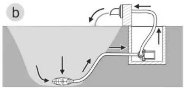
AMX0206
Environmental Function Control (EFC)
natural_image
Exploded view diagram of a mechanical assembly showing internal components and a 4x scale indicator (no text or labels)AMX0093
Tárolás/Telelés
natural_image
Diagram of a mechanical device submerged in a liquid channel with directional arrows indicating flow or movement (no text or symbols)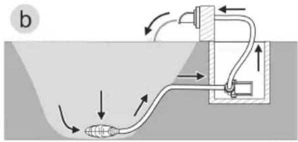
AMX0206
natural_image
Line drawing of a portable projector connected to a digital device via cable, with numbered callouts indicating components (no text or symbols present)AMX0095

AMX0092
Rozruch
WSKAZÓWKA
Environmental Function Control (EFC)
natural_image
Exploded view diagram of a mechanical assembly showing internal components and a 4x magnified detail (no text or labels)AMX0093
natural_image
Diagram of a mechanical device with fluid flow and directional arrows, no text or symbols present
AMX0206
Environmental Function Control (EFC)
natural_image
Exploded view diagram of a mechanical assembly showing internal components and a 4x scale indicator (no text or labels)AMX0093
Uložení/zazimování
natural_image
Diagram of a mechanical device with fluid flow and directional arrows, no text or symbols present
AMX0206
Environmental Function Control (EFC)
natural_image
Exploded view diagram of a mechanical assembly showing internal components and a 4x dimension label (no text or symbols beyond the scale indicator)AMX0093
Uloženie/prezimovanie
natural_image
Diagram of a mechanical device submerged in a liquid channel with directional arrows indicating flow or movement (no text or symbols)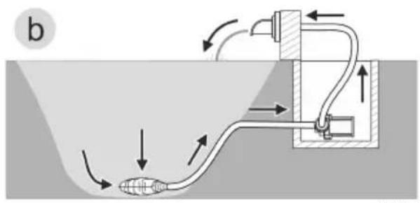
AMX0206
Environmental Function Control (EFC)
natural_image
Mechanical assembly diagram showing a shaft and housing with a 4x multiplier indicator (no text or symbols present)AMX0093
natural_image
Diagram of a mechanical device submerged in a liquid channel with directional arrows indicating flow or movement (no text or symbols)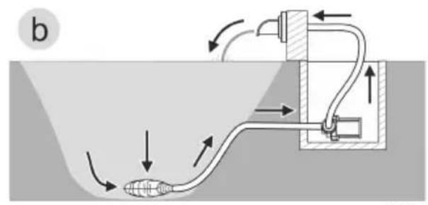
- Varijanta (a): Pumpu postaviti pod vodom
— Pumpa se postavlja u ribnjak odn. bazen.
— Potiskivanje vode preko filtarske košare. - Varijanta (b): Pumpu postaviti na suhom
- Pumpa se postavlja bez filtarske košare izvan ribnjaka odn. bazena, ali ispod razine vode.
— Potiskivanje vode preko pumpe filtra ili skimera.
AMX0206
Environmental Function Control (EFC)
Pumpa prilikom stavljanja u pogon, a zatim tijekom rada svakih 20 ... 40 minuta automatski obavlja unaprijed programiranu samoprovjeru (Environmental Function Control (EFC)). Pumpa prepoznaje radi li pritom na suho, je li blokirana ili uronjena. U slučaju rada na suho ili blokiranja, pumpa se automatski isključuje nakon otprilike 60 do 120 sekundi. U slučaju neispravnosti prekinite dovod elektroenergije i „potopite pumpu“ ili uklonite prepreku. Nakon toga možete uređaj ponovno staviti u pogon.
Rukovanje
Pregled upravljača
AMX0087
natural_image
Mechanical assembly diagram showing a shaft and housing with a 4x multiplier indicator (no text or symbols present)AMX0093
natural_image
Diagram of a mechanical device with fluid flow and directional arrows, no text or symbols present
natural_image
Diagram of a fluid system with pipe flow and valve components (no text or labels)AMX0206
Environmental Function Control (EFC)
natural_image
Exploded view diagram of a mechanical assembly showing internal components and a 4x scale indicator (no text or labels)AMX0093
natural_image
Diagram of a mechanical device with fluid flow and directional arrows, no text or symbols present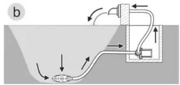
AMX0206
Environmental Function Control (EFC)
natural_image
Exploded view diagram of a mechanical assembly showing internal components and a 4x scale indicator (no text or labels)AMX0093
natural_image
Diagram of a mechanical device with fluid flow and directional arrows, no text or symbols present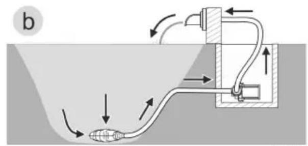
natural_image
Diagram of a fluid system with pipe flow and valve components (no text or labels)AMX0206
Environmental Function Control (EFC)
natural_image
Technical diagram of a mechanical device showing internal components and a numbered label (3), no readable text or symbols present.AMX0204
natural_image
Exploded view diagram of a mechanical assembly showing internal components and a 4x dimension label (no text or symbols beyond the scale indicator)AMX0093
natural_image
Diagram of a mechanical device with fluid flow and directional arrows, no text or symbols present
AMX0206
Environmental Function Control (EFC)
natural_image
Technical diagram of an open electronic device showing internal components and a labeled part (3), no text or symbols present.AMX0204
natural_image
Exploded view diagram of a mechanical assembly showing internal components and a 4x dimension label (no text or symbols beyond the scale indicator)AMX0093
natural_image
Diagram of a mechanical device submerged in a liquid channel with directional arrows indicating flow or movement (no text or symbols)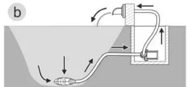
- 方式 (a): 在水下安装泵
- 将泵放置在池塘或水槽中。
- 通过过滤筐输水。
- 方式(b):在干燥环境下安装泵
AMX0206
先不要将电源插头插入插座!
安装
Environmental Function Control (EFC)
natural_image
Technical diagram of a mechanical device showing internal components and a numbered label (3), no readable text or symbols present.natural_image
Exploded view diagram of a mechanical assembly showing internal components and a 4x magnified detail (no text or labels)AMX0093