
Bitron Eco 120W - Water filter OASE - Free user manual and instructions
Find the device manual for free Bitron Eco 120W OASE in PDF.

| Brand | OASE |
| Model | Bitron Eco 120W |
| Product type | UV clarifier for pond |
| Dimensions (L × W × H) | 725 × 227 × 248 mm |
| Weight (without water) | 7.9 kg |
| Weight (with water) | 15.8 kg |
| Supply voltage | 220–240 V AC, 50/60 Hz |
| Power consumption | 120 W |
| UVC lamp type | 60 W TC-L (UV-C) |
| Lamp life | 12,000 hours |
| Allowed water temperature | +4 °C to +35 °C |
| Maximum flow rate | 50,000 l/h |
| Maximum operating pressure | 1 bar |
| Connections (inlet/outlet) | 38 mm (1½") and 50 mm (2") |
| Operating modes | 50%, 75%, 90%, 100% |
| Cleaning rotor | Yes, self-cleaning |
| By-pass regulation | Automatic |
| Protection class | IP24 |
| Mains cable length | 5 m |
| Wear parts | UVC lamp, quartz glass, O-ring, cleaning rotor |
| Cleaning | Outside with damp cloth; quartz glass and rotor must be cleaned periodically |
| Safety | Water splash protection; automatic shutdown when opened |
| Intended use | Garden ponds, natural swimming pools, aquariums (not drinking water) |
Frequently Asked Questions - Bitron Eco 120W OASE
User questions about Bitron Eco 120W OASE
0 question about this device. Answer the ones you know or ask your own.
Ask a new question about this device
Download the instructions for your Water filter in PDF format for free! Find your manual Bitron Eco 120W - OASE and take your electronic device back in hand. On this page are published all the documents necessary for the use of your device. Bitron Eco 120W by OASE.
USER MANUAL Bitron Eco 120W OASE
natural_image
Black industrial water purifier device with attached pipes and control panel (no visible text or symbols)Bitron Eco
120 W, 180 W, 240 W
EN Operating instructions
FR Notice d'emploi
BTN0003
Pos. Anzahl Bitron Eco 120 W, 180 W, 240 W
Eingang anschließen
DE
BTN0009
DE
BTN0011
Lagern/Überwintern
▶ Disconnect all electrical devices in the water from the power supply before reaching into the water. Otherwise there is a risk of severe injuries or death by electrocution.
This unit can be used by children aged 8 and above and by persons with reduced physical, sensory or mental capabilities or lack of experience and knowledge if they are supervised or have been instructed on how to use the unit in a safe way and they understand the hazards involved. Do not allow children to play with the unit. Only allow children to carry out cleaning and user maintenance under supervision.
Safety information
Electrical connection
- Special regulations apply for electrical installation in outdoor spaces. Only a qualified electrician may perform the electrical installation.
— The qualified electrician has the necessary professional training, knowledge and experience to perform electrical installation in outdoor spaces. The electrician can detect potential dangers and knows how to adhere to regional and national standards, regulations and directives.
— For your own safety, please consult a qualified electrician. - Only connect the unit if the electrical data of the unit and the power supply match.
- Only plug the unit into a correctly installed outlet. Ensure that the unit is fused for a rated fault current of max. 30 mA by means of a fault current protection device.
- Extension cables and power distributors (e.g. outlet strips) must be suitable for outdoor use (splash-proof).
- Protect open plugs and sockets from moisture.
Safe operation
- Do not use the unit, if electrical lines or the housing are damaged.
- Dispose of the unit if its power connection cable is damaged. The power connection cable cannot be replaced.
- Do not carry or pull the unit by its power cable.
- Route lines in such a way that they are protected from damage and do not present a tripping hazard.
- Never carry out technical changes to the unit.
- Only carry out work on the unit that is described in this manual.
- Only use original spare parts and accessories.
Intended use
Only use the product described in this manual as follows:
- For cleaning garden ponds, swimming ponds, pools and aquariums.
- While adhering to the technical specifications. (→Technical data)
The following restrictions apply to the unit:
- This product is not suitable for general lighting, but is only intended for the purpose described here.
- Never operate the UVC lamp outside the casing or use it for any other purposes. The UVC radiation is harmful to the eyes and skin even in small doses.
- Never use the unit with fluids other than water.
- Never run the unit without water.
- Do not use for commercial or industrial purposes.
- Not to be used for sterilising drinking water or other fluids.
- Do not use in conjunction with chemicals, foodstuff, easily flammable or explosive substances.
Product Description
Overview
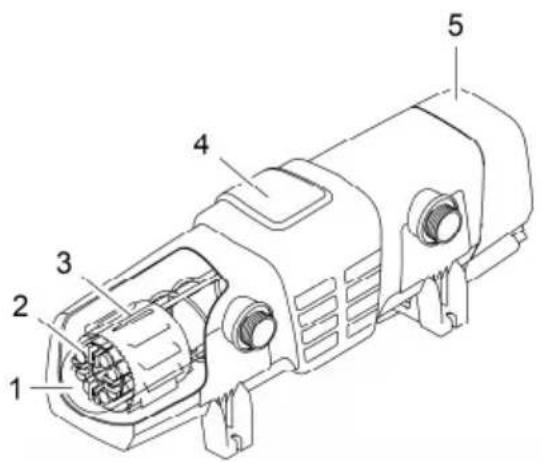
BTN0003
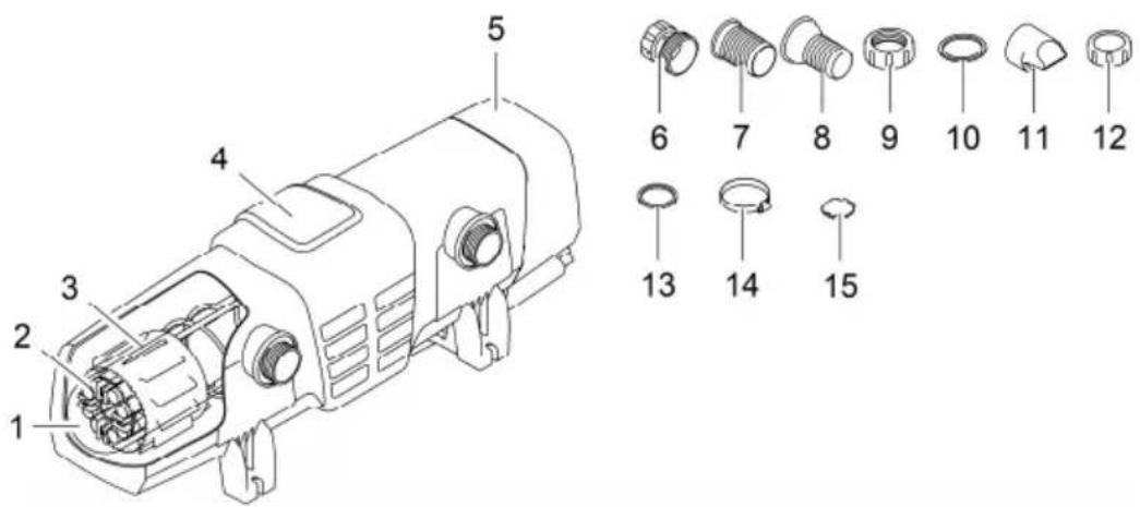
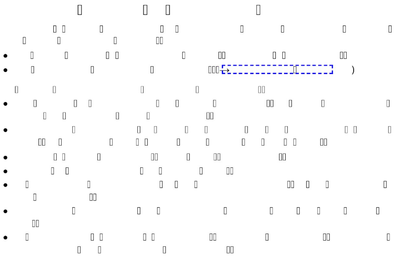
Item Quantity Bitron Eco 120 W, 180 W, 240 W
| 1 1 Quartz glass | |
| 2 UVC lamps | |
| 2 Bitron Eco 120W | |
| 3 Bitron Eco 180W | |
| 4 Bitron Eco 240W | |
| 3 1 Cleaning rotor | |
| 4 1 Casing | |
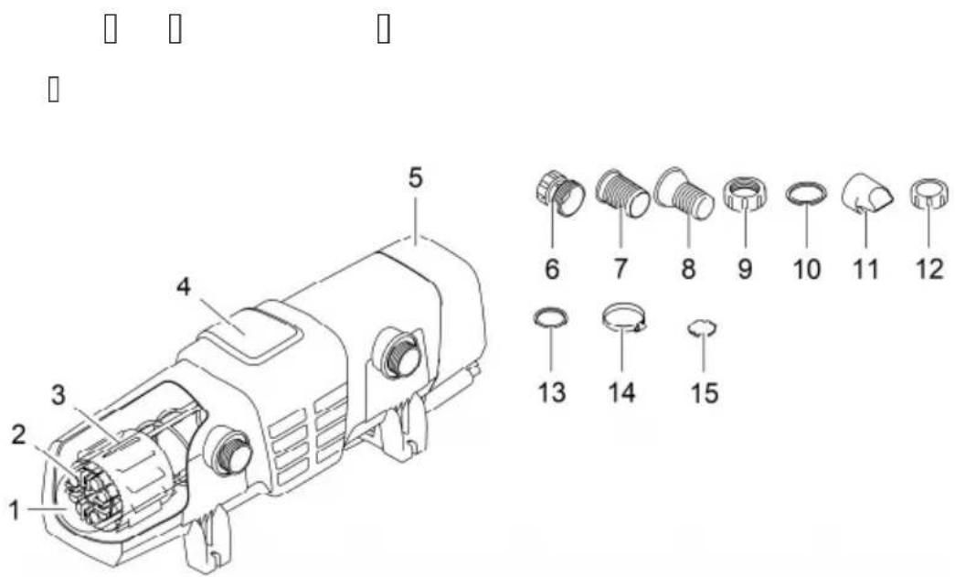
| 5 1 Unit head with control unit | |
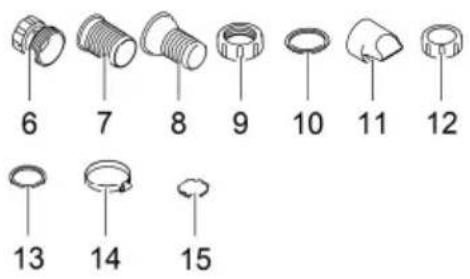
| Accessory kit with connection material: | |
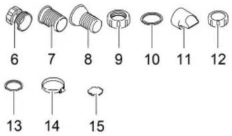
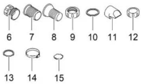
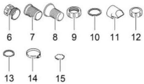
| 6 1 Adapter 38/50 mm (11⁄2 in / 2 in) for connection of the hose sleeve to the outlet | |
| 7 2 Hose sleeve 50 mm (2 in) for the inlet or outlet | |
| 8 2 Hose sleeves 38 mm (11⁄2 in) for the inlet or outlet | |
| 9 2 Union nut 50 mm (2 in) for fastening the hose sleeve (7, 8) | |
| 10 2 Flat seal 57 × 48 × 3 mm for the union nut (9) | |
| 11 1 Inlet nozzle for driving the cleaning rotorHas to be inserted into the inlet for flow rates < 10000 l/h | |
| 12 1 Cover cap 38 mm (11⁄2 in) for closing the outlet | |
| 13 2 Flat seal 45 × 33 × 3 mm for cover cap (12) and adapter (6) | |
| 14 2 Hose clip 40 ... 60 mm | |
15 1 Bypass closure for membrane holder
- Required for installation on the filter when an outlet needs to be closed.
- The membrane holder with bypass membrane is located in the outlet opposite the inlet (delivery state).
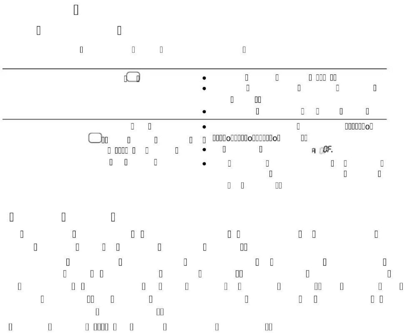
Control system overview
EN
BTN0007
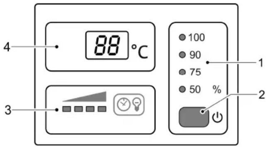
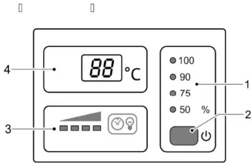
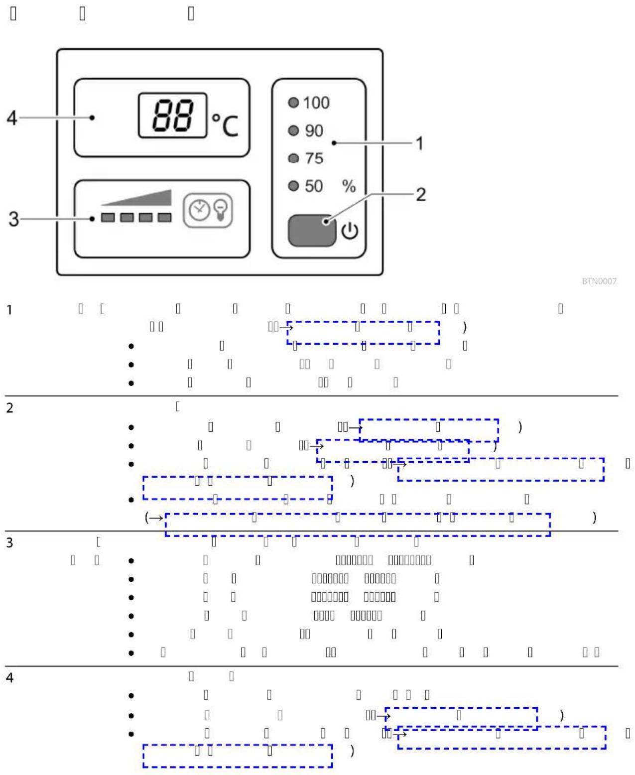
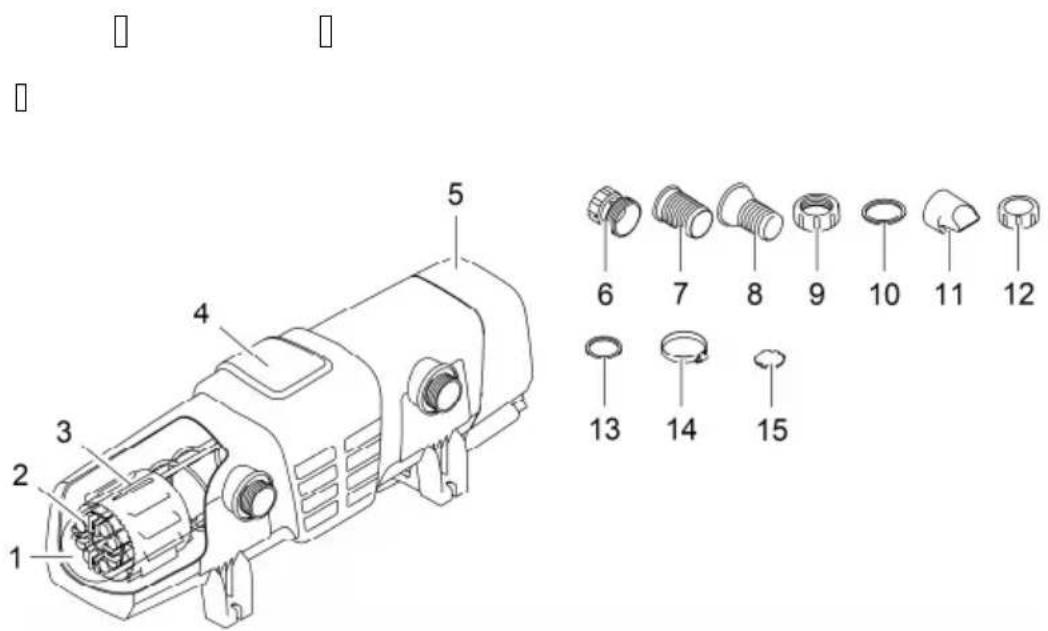
1 Operating mode Four operating modes for irradiation of algae and germs as required (→Selecting the operating mode)
• LEDs indicate the selected operating mode.
• LED is lit blue: UVC lamps are switched on.
• LED is lit green: UVC lamps are switched off.
2 Button Functions
- Switch on / switch off the unit(→Switching ON/OFF)
- Selecting the operating mode (→Selecting the operating mode)
- Checking the remaining operating life of the UVC lamps (→ Resetting the operating hour counter)
- Resetting the operating hour counter (→ Resetting the operating hour counter)
3 UVC lamp sta- LED bar for indicating the remaining operating life:
• Four LEDs lit: 9001 ... 12000 hours
• Three LEDs lit: 6001 ... 9000 hours
- Two LEDs lit: 3001 ... 6000 hours
• One LED lit: 1 ... 3000 hours
• One LED flashing: Replace UVC lamps.
- All LEDs unlit: At least one UVC lamp is defective.
4 Display Display of the operating status:
• Display of the current water temperature in °C
• Display of (→ System messages) System messages
- Display of the residual operating life of the UVC lamps (→ Resetting the operating hour counter)
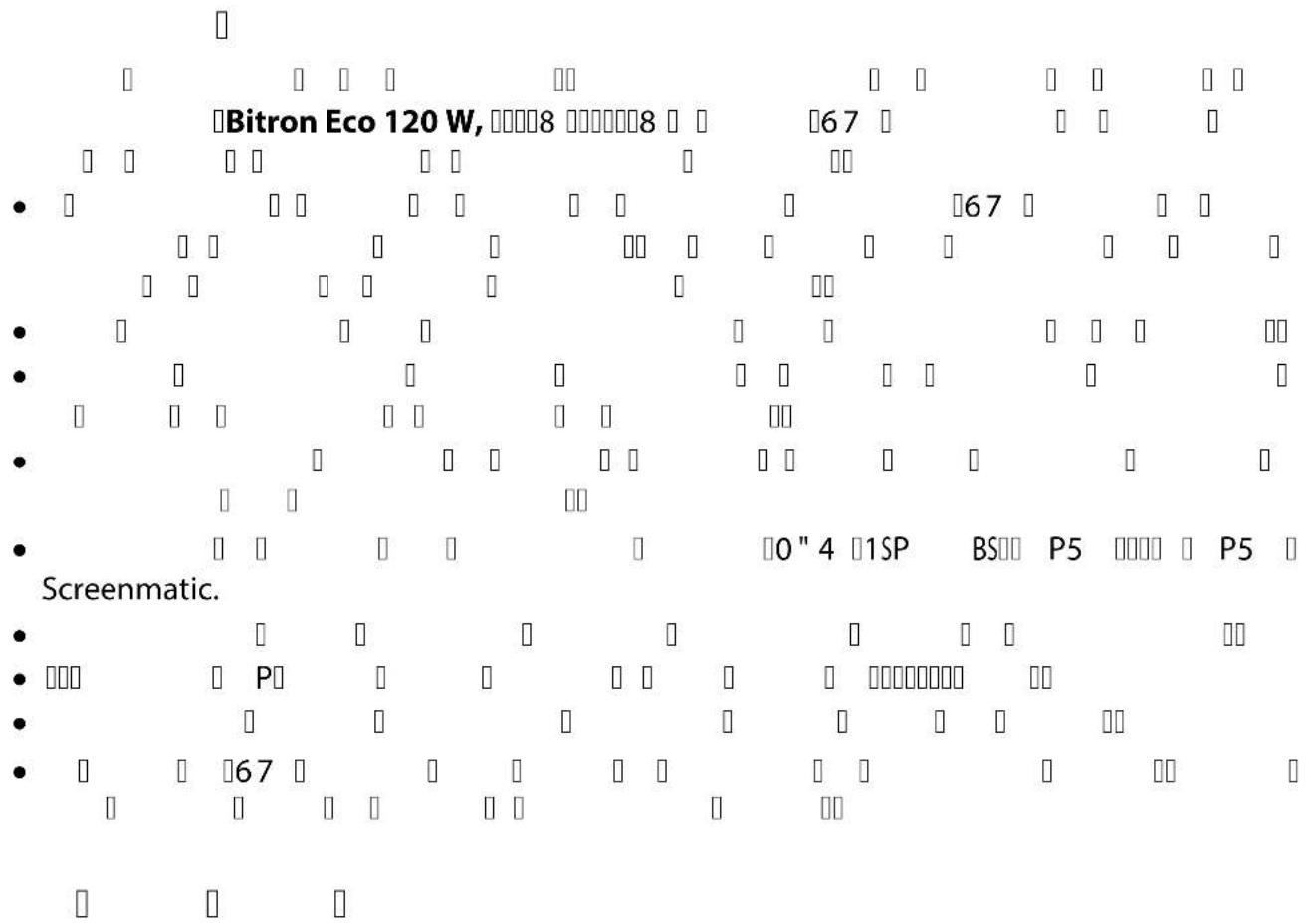
Properties
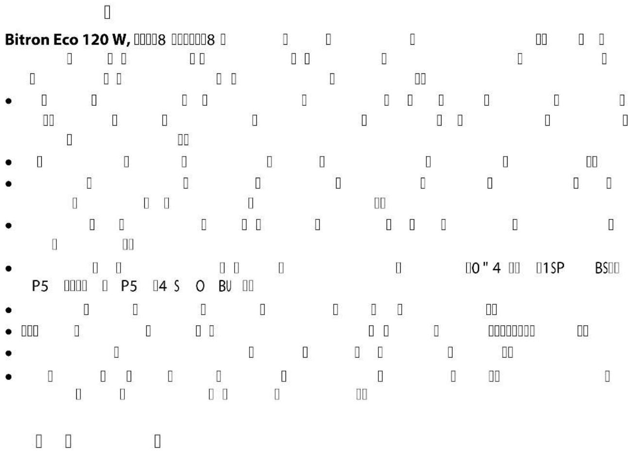
Bitron Eco 120 W, 180 W, 240 W is a powerful UVC clarifier for controlling algae and harmful bacteria thanks to its radiation output, water dwell time and thorough mixing action.
- The UVC lamps can be switched on and off as required based on the algal growth rates. This permits maximum results with minimum use of energy.
- The power level can be adjusted individually using the control unit.
- Fully automatic bypass control ensures an ideal combination of flow rate and radiation output.
- The long dwell time of the water in the high-volume casing increases the sterilising capacity.
- Suitable for use with OASE filter systems ProfiClear, BioTec 30 and BioTec Screenmatic.
- The cleaning rotor continuously removes soiling from the quartz glass.
- The 60 Watt Eco lamps are energy-saving and have an operating life of 12000 hours.
- The electronic ballast is virtually lossless.
- It is not necessary to remove the quartz glass to change the UVC lamps. The filter system is suitable for continuous operation.
Symbols on the unit
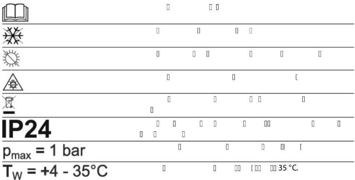
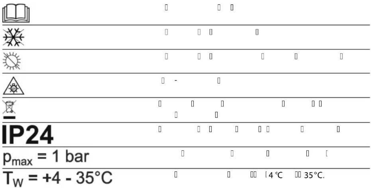
| Read the operating instructions. | |
| Protect the unit from freezing temperatures. | |
| Protect the unit from direct sunlight. | |
| Dangerous UVC radiation. | |
| Do not dispose of the unit with normal household waste. | |
| IP24 | The unit is protected against splash water and against contact with dangerous components. |
| p_max = 1 bar | Max. permissible operating pressure: 1 bar. |
| T_W = +4 - 35°C | Permissible water temperature: +4 °C to +35 °C. |
Installation and connection
Operation with pool water or salt water
- For operation with pool water or salt water, adhere to the following limits:
Type Pool water Salt water
| pH value 7.2 ... 7.6 7.5 ... 8.5 |
| Free chlorine 0.3 ... 0.6 mg/l < 0.3 mg/l |
| Bound chlorine < 0.2 mg/l - |
| Chloride content < 200 mg/l - |
| Salt content - < 3.5 % |
Water temperature +4 ... +30°C +4 ... +25°C
- Pool water or salt water can impair the appearance of the unit. Such impairments are excluded from the guarantee.
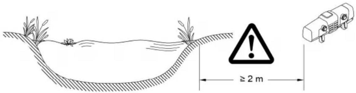
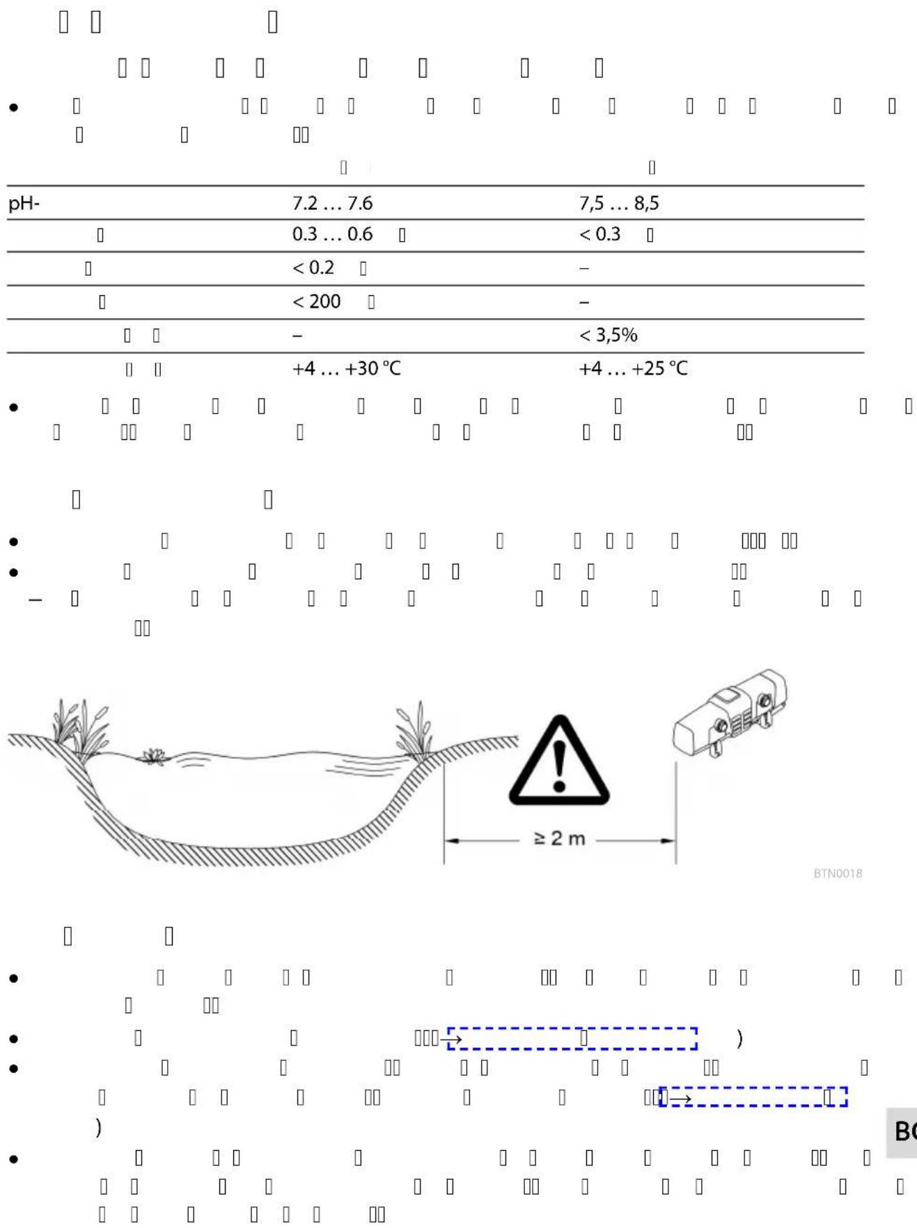
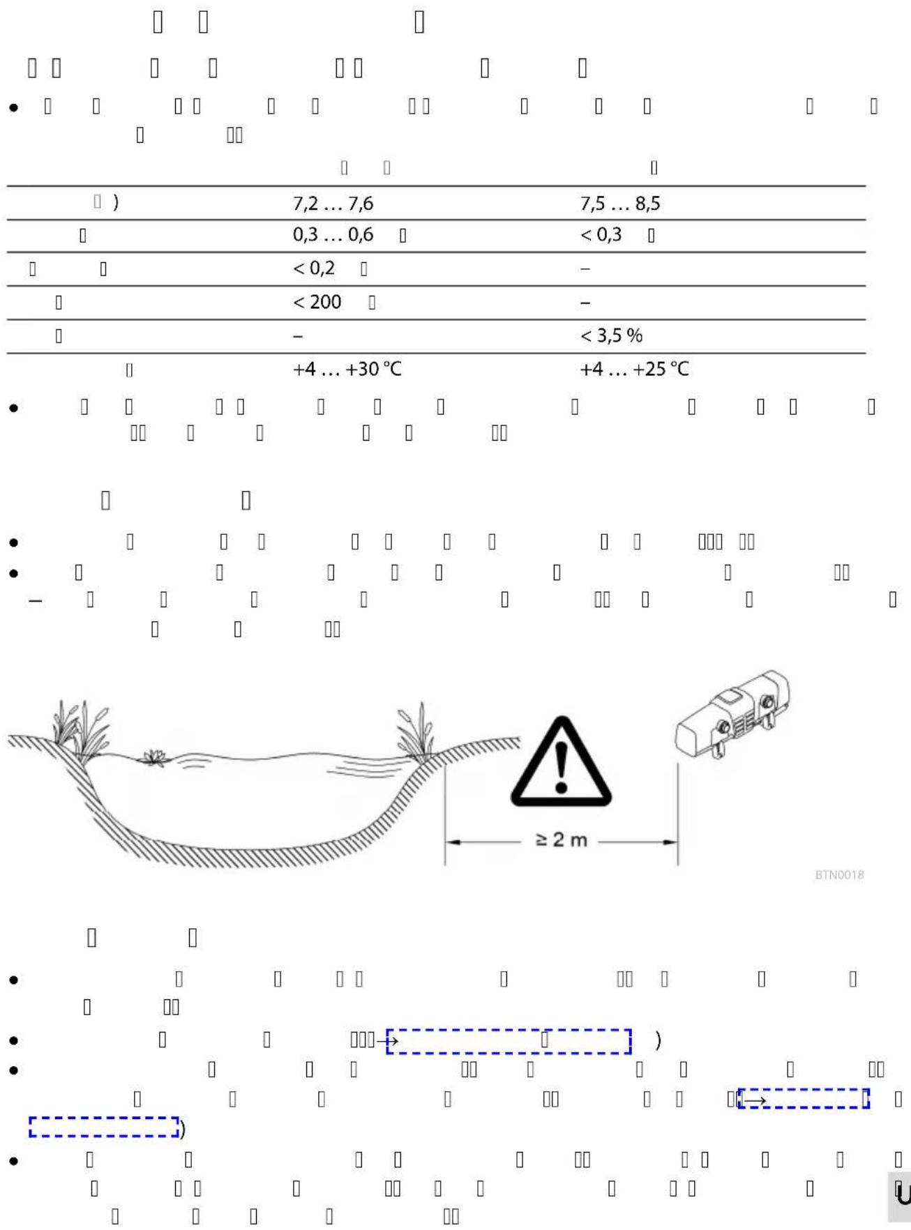
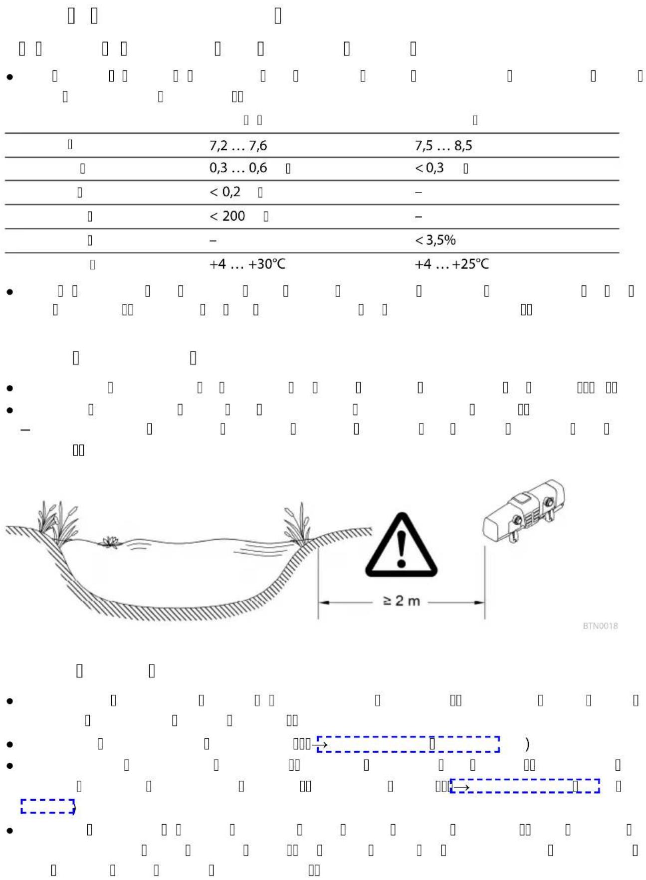
Distances to be adhered to
• Minimum safety distance between the unit and the water: 2 m.
- Allow sufficient space for carrying out maintenance work.
- Ensure that there is space of at least double the width of the casing for removing the unit head.
BTN0018
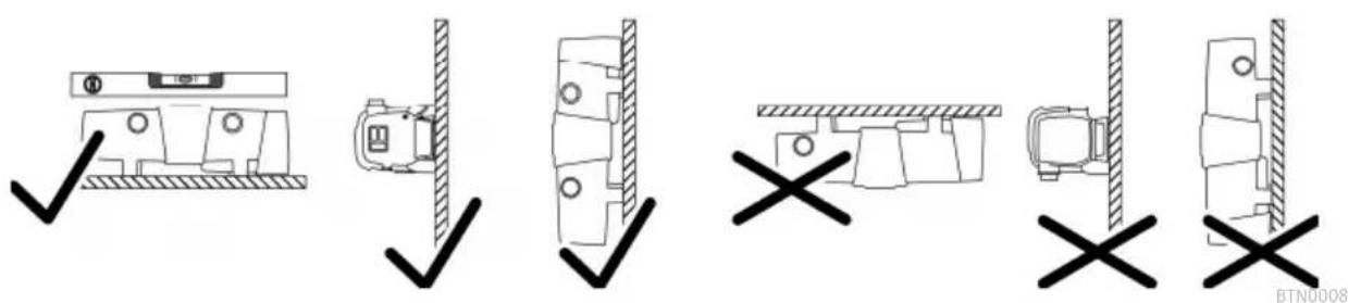
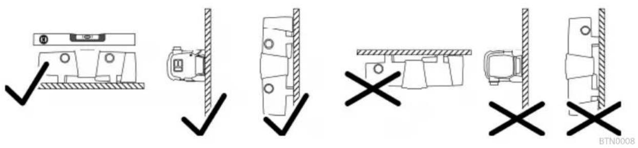
Solo operation
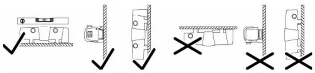
- Only install the unit in the permitted positions. This ensures fault-free operation.
- Take the required distances into consideration. (→Distances to be adhered to)
- Use suitable fastening material for the type of ground. Ensure that the fastening means securely hold the unit. Take the weight of the unit into consideration. (→Technical data)
- Fit a slide valve in the water supply upstream of the inlet of the unit if the unit is to be installed below the water level. This allows the water supply to be shut off for maintenance work.
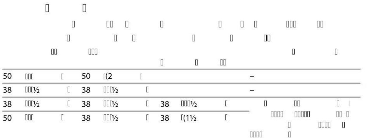
Connecting the inlet
Use hoses that are suitable for a pressure of at least 1 bar.
Recommended combinations for using the hose sleeves:
Inlet Outlet 1 Outlet 2
Required accessories
| (opposite the inlet) | |
| 50 mm (2 in) 50 mm (2 in) closed - | |
| 38 mm (1 12 in) 38 mm (1 12 in) closed - | |
| 38 mm (1 12 in) 38 mm (1 12 in) 38 mm (1 12 in) For outlet 2 , a 38 mm (1 12 in) | |
| 50 mm (2 in) 38 mm (1 12 in) 38 mm (1 12 in) | hose sleeve with a 38 mm (1 12 in) union nut |
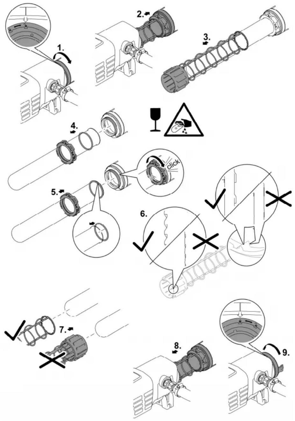
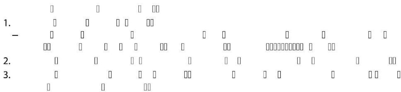
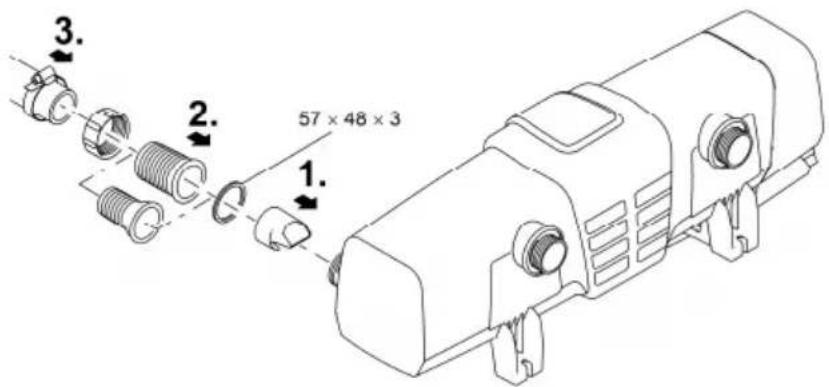
How to proceed:
- Push the inlet nozzle into the inlet.
- The inlet nozzle is only necessary for a flow rate < 10000 ~l / h to ensure unimpaired rotation of the cleaning rotor.
- Screw the hose connector with union nut and seal onto the inlet.
- Slip the hose clip over the hose, fit the hose onto the hose connector and secure with the hose clip.

BTN0004
Connecting the outlet
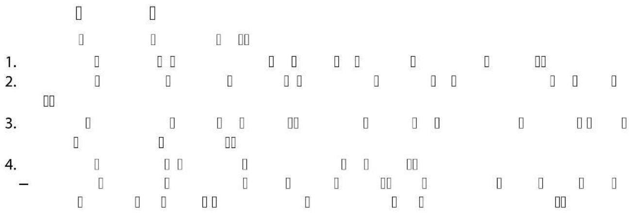
How to proceed:
- Screw the adapter with seal onto the outlet and hand tighten.
- Screw the stepped hose adapter with union nut and seal onto the adapter.
- Slip the hose clip over the hose, fit the hose onto the hose connector and secure with the hose clip.
- Screw the cover cap with flat seal onto the outlet.
— The cover cap has to close the outlet opposite the inlet so that the main flow of water is guided along the UVC lamps and is exposed to the UV radiation for as long as possible.

BTN0013
Connect the unit to the flow-through filter
- Take the required distances into consideration. (→Distances to be adhered to)
- Fit a slide valve in the water supply upstream of the inlet of the unit if the unit is to be installed below the water level. This allows the water supply to be shut off for maintenance work.
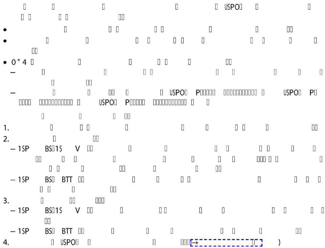
ProfiClear Premium / ProfiClear Classic
This section describes the connection of the UVC clarifying unit Bitron with a pump fed system.
- Please adhere to the instructions for use of the flow-through filter.
- The bypass membrane is fitted on delivery and is located in the outlet opposite the inlet.
- OASE recommends closing the bypass in the following situations:
— Acute problems such as disease or turbidity due to a build-up of bacteria.
- Low flow rates:
Bitron Eco 120 W: < 10000 l/h
Bitron Eco 180 W: < 13000 l/h
Bitron Eco 240 W: < 15000 l/h
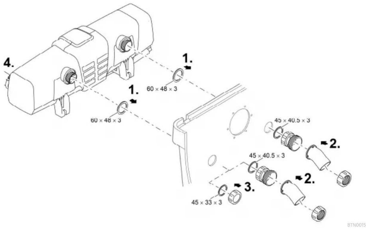
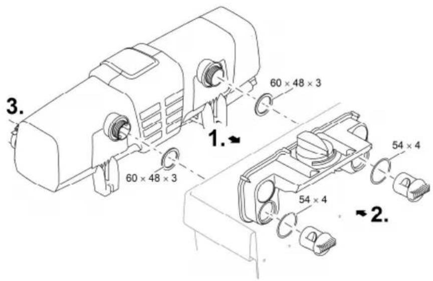
How to proceed:
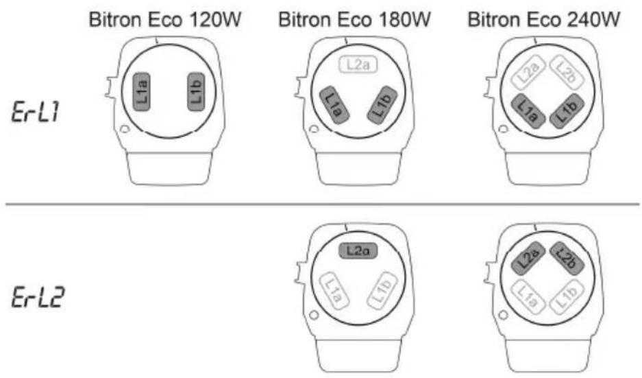
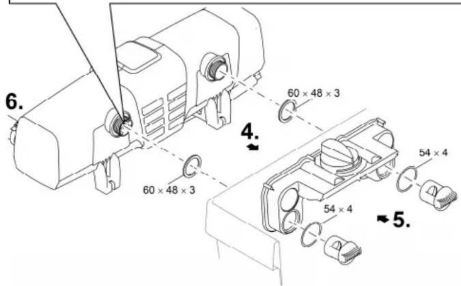
- Insert the outlets with flat seals through the holes in the container wall.
- Fitting the inlet:
— ProfiClear Premium: First screw the adapters onto the outlets and hand tighten. Then screw the 30° inlet bends with the union nuts onto the adapters and hand tighten. Ensure that the openings point downward.
— ProfiClear Classic: Screw the inlet nozzles with the O rings onto the outlets and hand tighten.
- Closing the bypass (optional):
— ProfiClear Premium: Screw the cover cap onto the outlet instead of the adapter and inlet bend.
— ProfiClear Classic: Screw the cover cap onto the outlet instead of the inlet nozzle.
- Connect the Bitron to the filter pump. (→ Connecting the inlet)

BTN0017
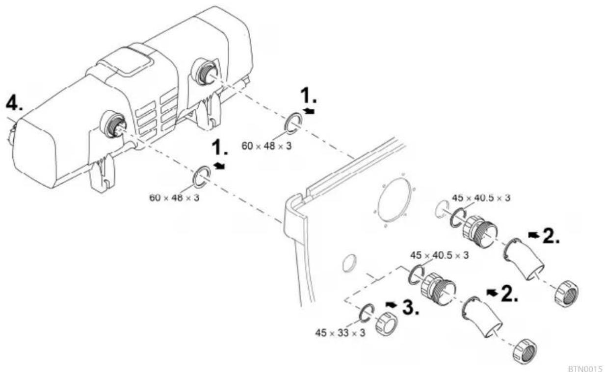
BioTec ScreenMatic
- Please adhere to the instructions for use of the flow-through filter.
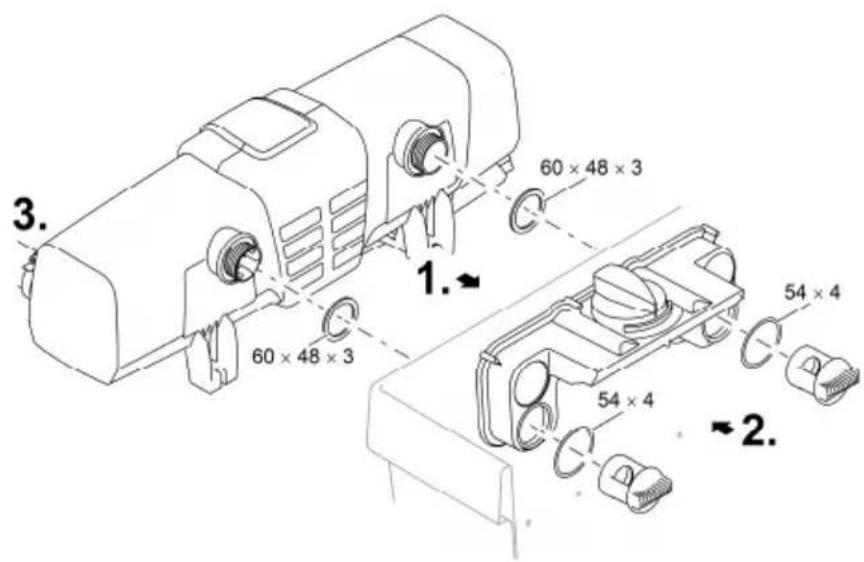
With bypass
- The bypass membrane is fitted on delivery and is located in the outlet opposite the inlet.
How to proceed:
- Insert the outlets with flat seals through the holes in the container wall into the distributor.
- Screw the distributor nuts with O rings onto the outlets and hand tighten.
- Connect the Bitron to the filter pump. (→ Connecting the inlet)
BTN0005
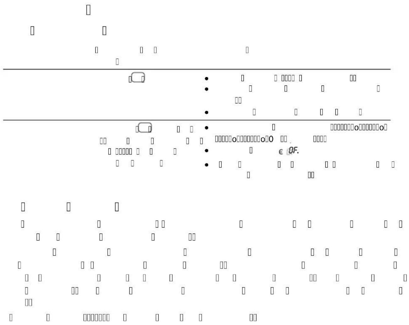
Without bypass
- OASE recommends closing the bypass in the following situations:
— Acute problems such as disease or turbidity due to a build-up of bacteria.
- Low flow rates:
Bitron Eco 120 W: < 10000 l/h
Bitron Eco 180 W: < 13000 l/h
Bitron Eco 240 W: < 15000 l/h
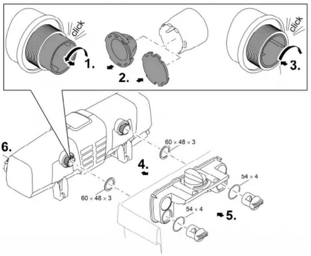
How to proceed:
- Turn the bypass holder counterclockwise until it makes an audible click and remove it from the outlet.
- Pull the bypass membrane out of the bypass holder and fit the bypass closure onto the bypass holder.
— The bypass closure can only be fitted onto the bypass holder in one position. - Insert the bypass holder into the outlet and turn it clockwise until it makes an audible click.
— The bypass holder is locked in place. - Insert the outlets with flat seals through the holes in the container wall into the distributor.
- Screw the distributor nuts onto the outlets and hand tighten.
- Connect the Bitron to the filter pump. (→ Connecting the inlet)

BTN0016
Commissioning/start-up
NOTE
The unit may be damaged, if the water flow is suddenly interrupted downstream of the outlet (e.g. by a slide valve). The sudden interruption can cause a temporary pressure increase of over 1 bar (hydraulic shock).
▶ Switching off: First switch off the pump, then close the slide valve. If the unit is operated in a filter system, first take the filter system out of operation.
▶ Switching on: First open the slide valve, then switch on the pump. If the unit is operated in a filter system, start up the filter system last.
As an alternative, install the slide valve upstream of the inlet.
It takes approx. 3 to 4 weeks before the micro-organisms in new filters are fully established. During this time – or at a water temperature of <10 ^ – the filter may overflow. In this case the filter does not need to be cleaned.
- When using filter starters, medicines or pond water treatments, leave the UVC pre-clarifier switched off for at least 36 hours so as not to impair their efficacy.
① On delivery, the unit is turned off. OF is indicated on the display.
- In new pond installations, wait at least 36 hours after set-up to start UV irradiation to ensure that a stable pond biology can develop as quickly as possible.
Order of starting up steps
- Switch on the pump.
- Check all connections for leaks.
- Connect the unit to the power supply.
— The unit switches on with the last selected operating mode.
- Switch on the unit if necessary. (→ Switching ON/OFF)
- Select the operating mode.
- A garden pond is subject to a number of different influencing factors that encourage algae growth (e.g. direct sunlight, nutrient contamination, natural planting). Therefore the suitable Eco mode can only be individually determined.
- Observe the information regarding the selection of a suitable operating mode. (→ Selecting the operating mode)
Operation
Switching ON/OFF
Function Proceed as follows Note
| Switching on | Press ☐ | The operating mode "50%" is active.The display indicates the current water temperature.The status display of the UVC lamps is lit. |
| Switching off | Press several times until the UVC lamps turn off after operating mode "100%". | Switching sequence: 50% – 75% – 90% – 100% – Off.The display indicates OF.In the event of an error, the corresponding error message is displayed. |
Selecting the operating mode
It is possible to choose from four operating modes to match irradiation of algae and germs to the requirements of the situation.
The duration of irradiation is automatically controlled on the basis of the measured water temperature and the selected operating mode. The ratio of the switch-on time to the switch-off time of the UVC lamps is dependent upon the operating mode. The higher the percentage value, the longer the switch-on time in relation to the switch-off time.
In 100% operating mode, the UVC lamps are permanently switched on.
Function Proceed as follows Note
| Selecting the operating mode | Press until you reach the desired operating mode. | Switching sequence: 50% – 75% – 90% – 100% – Off.UVC lamps on: LED is lit blue:UVC lamps off: LED is lit green (energy-saving phase in Eco mode).Select Eco mode 50% if the water is only slightly soiled.Select Eco mode 75% or 90% if the water is more soiled.Select operating mode 100% if the water is very soiled.How to proceed if the water is green:Start with operating mode 100%. As soon as the desired result is achieved, change to Eco mode 50%. If the water becomes green again, choose the next higher Eco mode until you achieve the desired result permanently.How to proceed if the water is clear:Start with Eco mode 50%. If the water starts to go green, select the next higher Eco mode until you achieve the desired result permanently. |
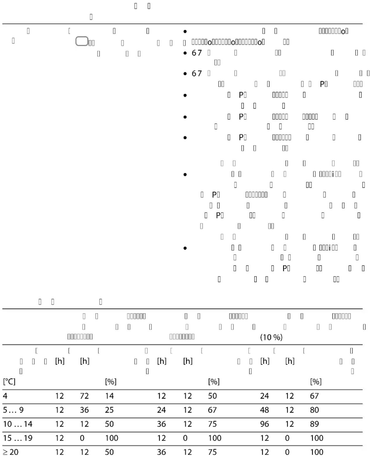
Switching times
| Operating mode 50 %High saving in energy (50 %) | Operating mode 75 %Medium saving in energy(25 %) | Operating mode 90 %Low saving in energy (10 %) | |||||||
| Water temperature[°C] | On[h] | Off[h] | Irradiation duration[%] | On[h] | Off[h] | Irradiation duration[%] | On[h] | Off[h] | Irradiation duration[%] |
| 4 12 72 14 12 12 50 24 12 67 | |||||||||
| 5 ... 9 12 36 25 24 12 67 48 12 80 | |||||||||
| 10 ... 14 12 12 50 36 12 75 96 12 89 | |||||||||
| 15 ... 19 12 0 100 12 0 100 12 0 100 | |||||||||
| ≥ 20 | 12 12 50 36 12 75 12 0 100 | ||||||||
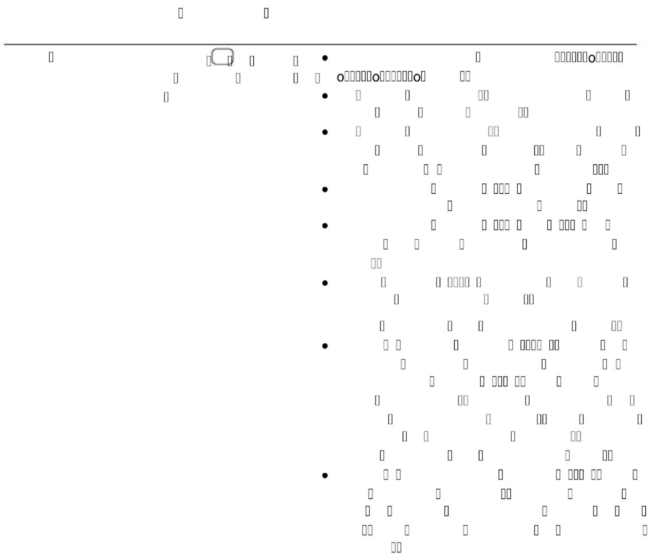
Resetting the operating hour counter
When the UVC lamps reach their maximum operating life, the LED of the UVC lamp status displays starts flashing. Replace the UVC lamps to achieve the optimum irradiation output. Then reset the operating hour counter.
- You can check the exact remaining operating life of the UVC lamps on the display.
| Function | Proceed as follows | Note |
| Checking the remaining operating life of the UVC lamps | Press and hold for approx. 6 s. | The 6-digit value is displayed in groups of two digits that appear in succession on the display.This is repeated three times after an extended pause to make it easier to read the number.Example:01-11-54---01-11-54---01-11-5401-11-54 indicates that 11154 hours of operating life remain |
| Resetting the operating hour counter | Press and hold for approx. 6 s until the status of the UVC lamps is displayed.While the status of the UVC lamps is displayed:Press again and hold it until all four LEDs of the UVC lamp status display are flashing and rE is no longer displayed. | When rE disappears, the operating hour counter has been reset to 12000 hours.If the button is released too early, the operating hour counter is not reset. |
Maintenance and cleaning
NOTE
Do not use aggressive cleaning agents or chemical solutions. These agents can damage the housing, impair the function of the device and harm animals, plants and the environment.
▶ Clean only the outside of the unit with a damp cloth.
- Recommended cleaning agent for removing stubborn limescale deposits:
— Pump cleaning agent PumpClean from OASE.
— Vinegar- and chlorine-free household cleaning agent.
Regular tasks
Check at regular intervals that the unit is functioning perfectly. Determine suitable intervals depending on the unit operating time and soiling of the water. The higher the demands on cleaning, the more often you must check the unit. Check the following:
- Unit status on the control system. (→Control system overview)
- Function of the cleaning rotor. A visual inspection is possible when the unit head is removed. (→ Dismantling the unit head)
— Use a torch to improve visibility.
Dismantling the unit head
CAUTION
The ultra-violet radiation of the UVC lamp can damage your eyes and skin.
▶ Never operate the UVC lamp outside its housing.
▶ Disconnect the unit from the mains before starting maintenance or before replacing the UVC lamp.
CAUTION
The quartz glass and UVC lamp could break and result in cuts.
- Carry out all work on the UVC clarifier carefully to avoid cutting injuries.
- Avoid vibrations, impacts and hectic movements to prevent the breaking of glass.
CAUTION
Lamp is hot. Risk of burns due to contact with the lamp.
▶ Switch off the UVC clarifier and wait several minutes for the lamp to cool down before removing it.
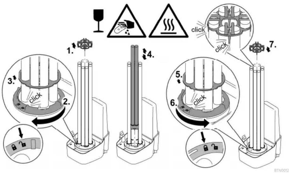
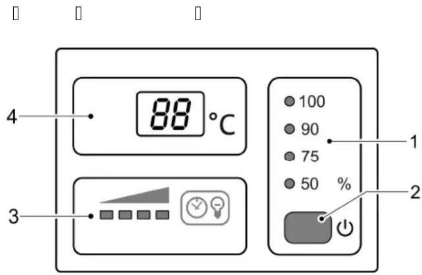
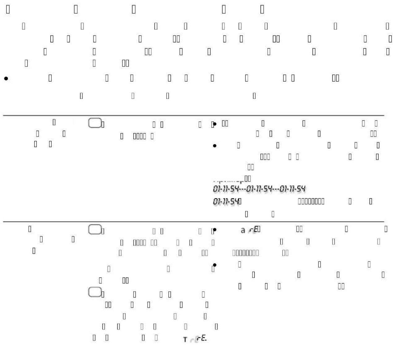
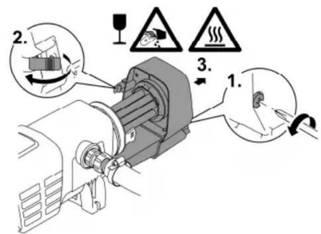
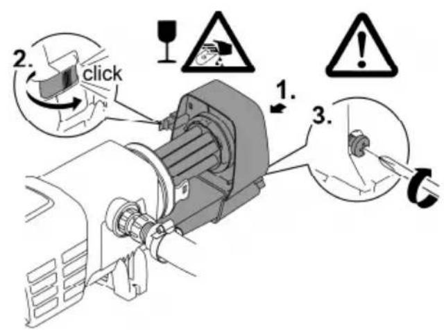
How to proceed:
- Unscrew the locking screw until it is pushed out by a spring.
— The locking screw cannot be completely unscrewed. - Undo the engagement hook.
- Carefully pull the unit head out of the casing.
For safety reasons, the UVC lamp can only be turned on when the UVC clarifier is properly installed into the device.

EN
BTN0006
Fitting the unit head
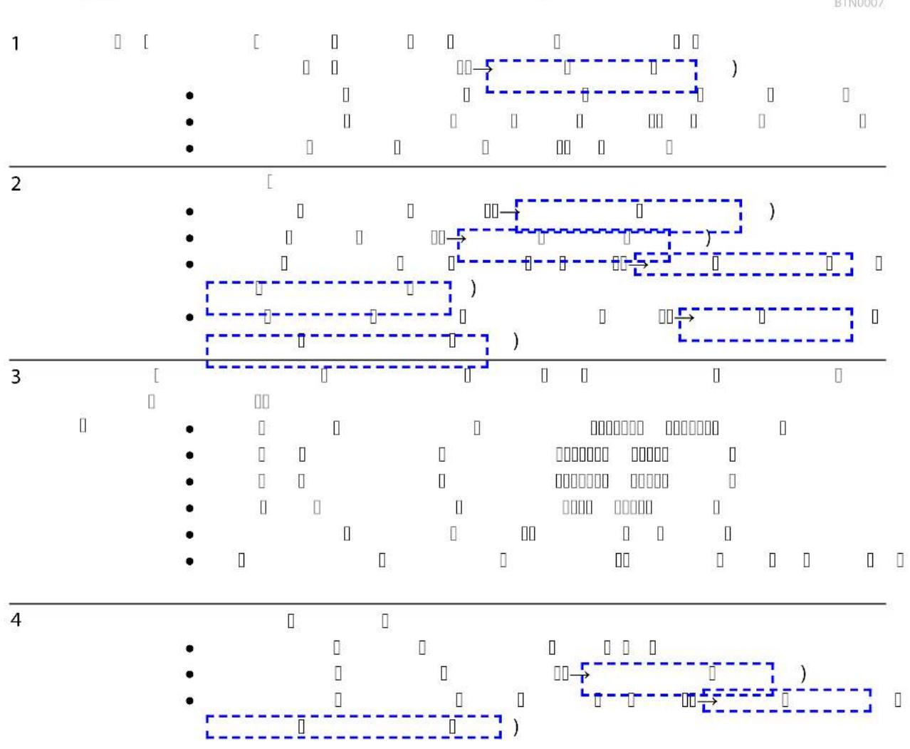
How to proceed:
- Carefully push the unit head into the casing.
- Lock the unit head in place with the engagement hook.
- Screw in the locking screw and hand tighten.
— The unit is only protected from the ingress of moisture if the locking screw is tightened.

BTN0010
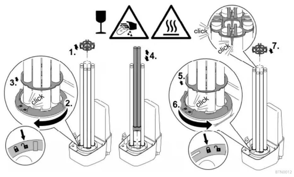
Exchange the UVC lamp
Replace the UVC lamps after max. 12000 operating hours. This ensures optimum filtering performance.
- An LED is flashing in the LED bar of the control system. This status display indicates that the UVC lamps need changing.
- Only use UVC lamps, the identification and power data of which correspond to the information on the type plate. (→Technical data)
Prerequisite:
- The unit head is removed. (→Dismantling the unit head)
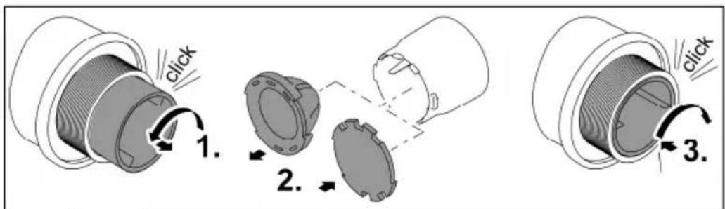
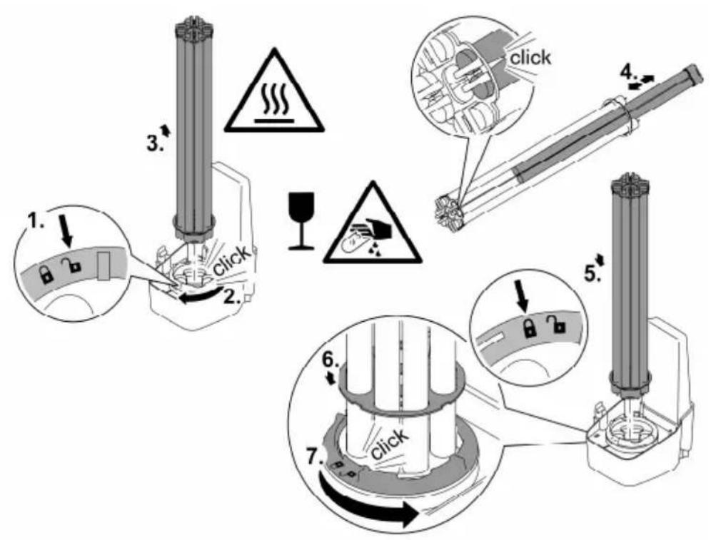
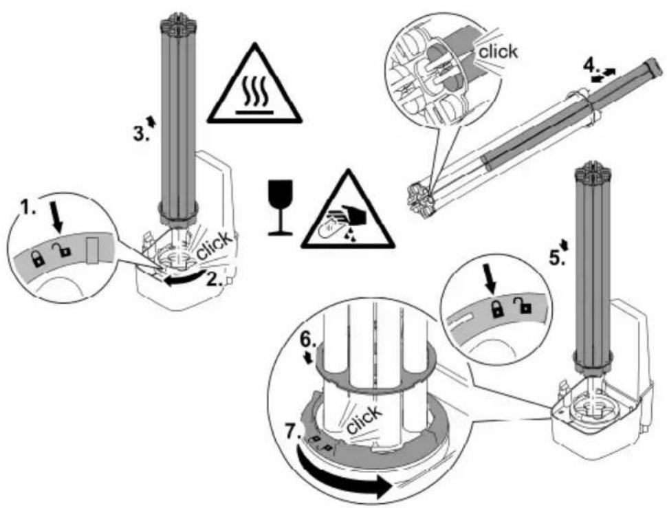
How to proceed:
- Turn the locking ring counterclockwise as far as the stop.
- Rotational direction "Lock open" symbol.
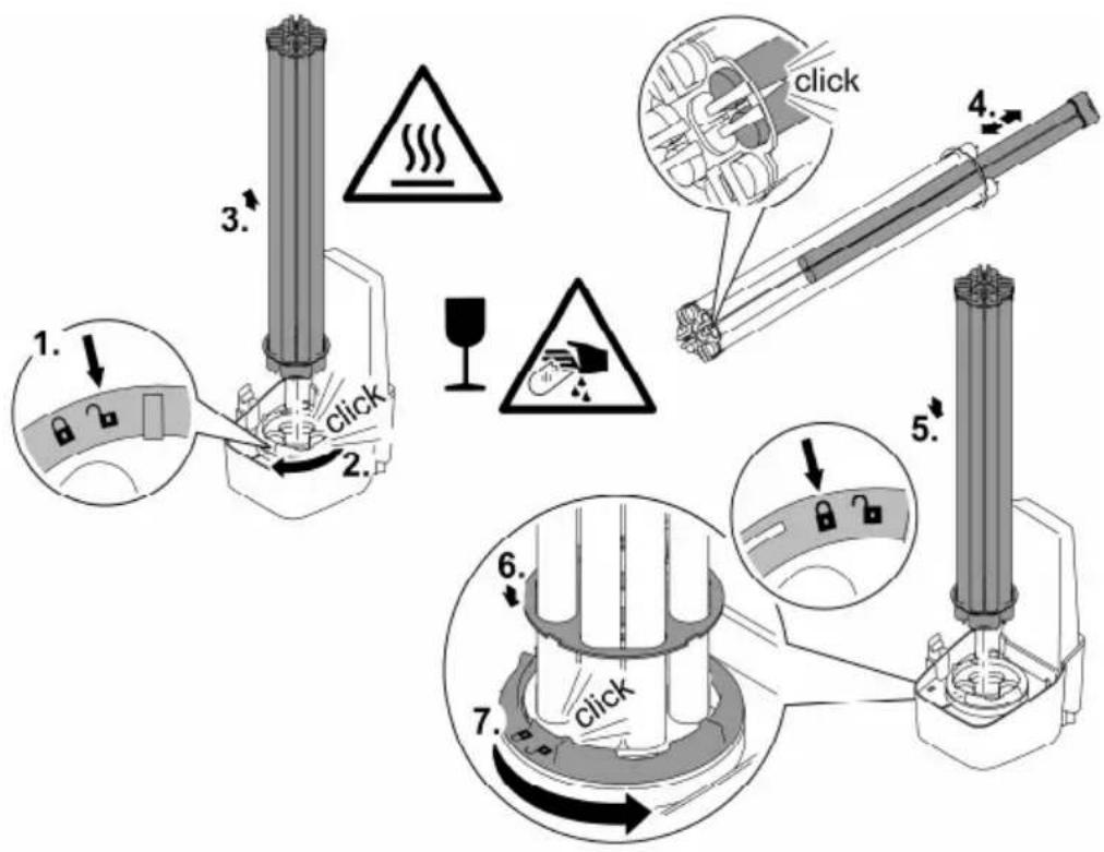
- Carefully pull the UVC lamp package out of the lamp sockets in the unit head.
- Replace the UVC lamps.
- Soiling can burn into the lamp glass and can impair the operating life of the UVC lamps.
Therefore only touch the UVC lamps with a cloth or clean gloves.
— Carefully release the old UVC lamps from the lamp holder and pull out of the retaining plate.
- Push the new UVC lamps through the retaining plate until the lamp head locks into place in the lamp holder.
- Carefully insert the UVC lamp package into the lamp sockets in the unit head.
- Push the retaining plate onto the locking ring.
- Turn the locking ring clockwise as far as the stop.
- Rotational direction "Lock closed" symbol.
— The locking device fixes the retaining plate such that the UVC lamps are firmly seated in the lamp sockets.
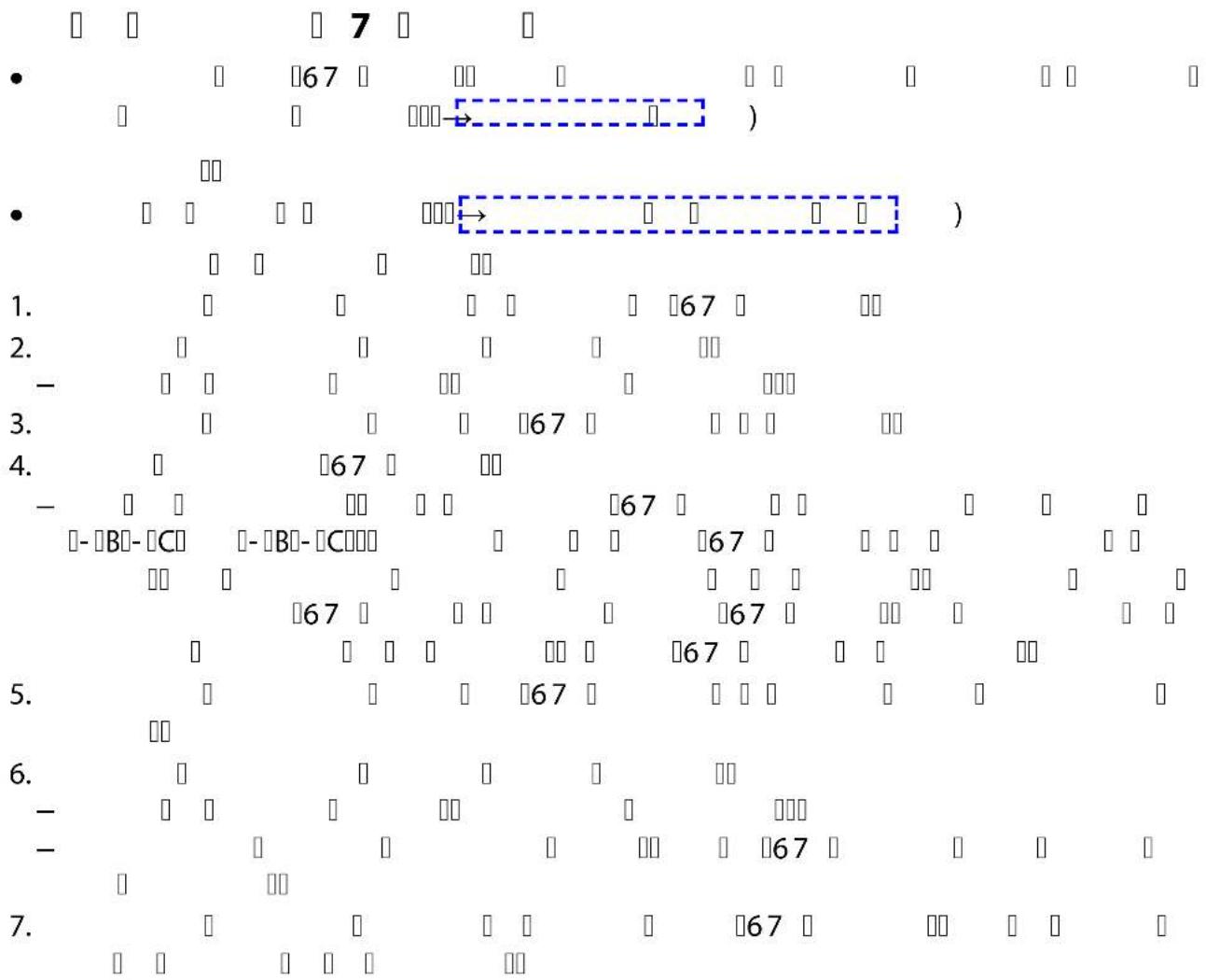
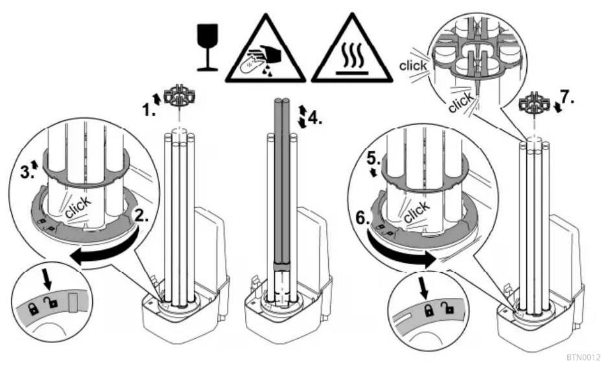
Replacing a defective UVC lamp
- Only use UVC lamps, the identification and power data of which correspond to the information on the type plate. (→Technical data)
Prerequisite:
- The unit head is removed. (→Dismantling the unit head)
How to proceed:
- Carefully pull the lamp holder from the UVC lamps.
- Turn the locking ring counterclockwise as far as the stop.
- Rotational direction "Lock open" symbol.
- Guide the retaining plate over the UVC lamps and remove.
- Change the defective UVC lamp.
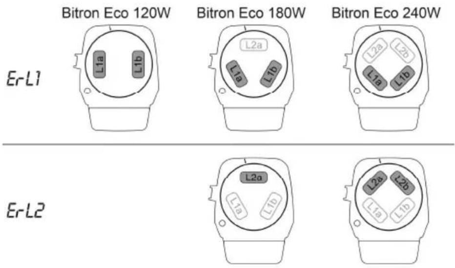
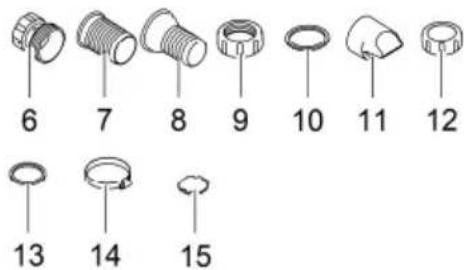
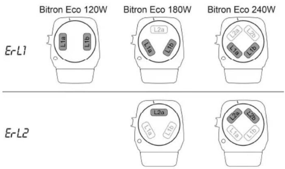
- How to determine which UVC lamp of the respective lamp pair is defective (L1a/L1b or L2a/L2b): Change one of the two UVC lamps and assemble the unit. If the system message is still displayed, reinsert the UVC lamp and change the other UVC lamp. If the system message is still displayed, both UVC lamps are defective.
- Guide the retaining plate over the UVC lamps and push it onto the locking ring.
- Turn the locking ring clockwise as far as the stop.
— Rotational direction "Lock closed" symbol.
— The locking device fixes the retaining plate such that the UVC lamps are firmly seated in the lamp sockets. - Carefully press the lamp holder onto the UVC lamps such that all lamp heads engage.

BTN0002
Cleaning/replacing the quartz glass
CAUTION
The quartz glass and UVC lamp could break and result in cuts.
Carry out all work on the UVC clarifier carefully to avoid cutting injuries.
- Avoid vibrations, impacts and hectic movements to prevent the breaking of glass.
NOTE
The unit may be damaged, if the water flow is suddenly interrupted downstream of the outlet (e.g. by a slide valve). The sudden interruption can cause a temporary pressure increase of over 1 bar (hydraulic shock).
▶ Switching off: First switch off the pump, then close the slide valve. If the unit is operated in a filter system, first take the filter system out of operation.
▶ Switching on: First open the slide valve, then switch on the pump. If the unit is operated in a filter system, start up the filter system last.
As an alternative, install the slide valve upstream of the inlet.
Prerequisite:
- The unit head is removed. (→Dismantling the unit head)
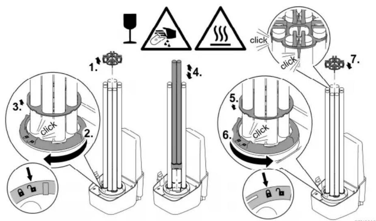
How to proceed:
- Turn the casing cover counterclockwise as far as the stop.
- Rotational direction symbol "Open lock".
— The casing cover can be very firmly seated. If necessary, insert a rod through the lugs to achieve greater leverage.
-
Carefully pull the quartz glass and cleaning rotor out of the casing.
-
Clean the quartz glass and the cleaning rotor.
— Pull off the cleaning rotor and clean with a brush under running water.
— Wipe the quartz glass with a damp cloth.
— Thoroughly clean the inner and outer surfaces of the casing.
- Replace the quartz glass if it is damaged or very scratched.
— Undo the clamping screw and pull the quartz glass, together with the O ring, from the casing cover.
- Clean the O ring and lubricate with OASE grease (order No. 27872). Replace the O ring if it is damaged.
- Fit the quartz glass together with the O ring onto the casing cover and screw in the clamping screw as far as the stop.
— Pull the O ring over the flanged rim to avoid grease residue coming into contact with the quartz glass.
- Ensure that the clamping screw audibly engages, otherwise the casing cover cannot be fitted into the casing.
- Check the profile wear at both ends and the inner surfaces on the cleaning rotor.
- If the profile is worn, the cleaning rotor rotates sluggishly and has to be replaced.
- Push the cleaning rotor onto the quartz glass.
- Ensure that it is correctly positioned.
-
Carefully push the quartz glass and the cleaning rotor into the casing.
-
Turn the casing cover clockwise as far as the stop.
- Rotational direction symbol "Close lock".
BTN0011
Storage/winter protection
The unit is protected from frost (e.g. stored in a garage or other enclosure)
The unit can be operated as long as the water temperature does not go below +4 °C.
The unit is not protected from frost (e.g. outdoor installation)
Remove the unit at temperatures below zero degrees centigrade. Thoroughly clean and check the unit for damage.
EN
Malfunction remedy
Malfunctions
Malfunction Cause Remedy
| Water remains cloudy (green water). | Water is extremely soiled or contaminated. | Remove algae and leaves from the pond.Clean the pond thoroughly.Change the water, remove algae and leaves from the pond.Clean the pond thoroughly.Change the water. |
| Insufficient circulation of the pond water. | Ensure that the pond water is sufficiently recirculated.Place the pump in a different position.Use a pump with a higher circulation capacity. | |
| Capacity of the UVC lamps is not sufficient. | Change the UVC lamps after 12000 operating hours. | |
| The quartz glass is soiled. Clean the quartz glass.(→Cleaning/replacing the quartz glass) | ||
| The quartz glass is scratched. | Replace the quartz glass(→Cleaning/replacing the quartz glass)If the profile is worn, replace the cleaning rotor (→Cleaning/replacing the quartz glass) | |
| Unit is deactivated. | Exit OF mode and select Eco mode. | |
| The quartz glass is soiled as the cleaning rotor is not rotating.Inspection: Remove the unit head, switch on the filter pump and shine a torch into the casing. | Clean the cleaning rotor and (→Cleaning/replacing the quartz glass) quartz glassIf the delivery rate of the pump is < 10000 l/h, use an inlet nozzle for driving the cleaning rotor.If the profile is worn, replace the cleaning rotor (→Cleaning/replacing the quartz glass) | |
Unit is not functional. Power plug not connected Connect the power plug.
Connection defective Check the electrical connection
Malfunction Cause Remedy
| Lamp does not light up. Safety switch-off activated. For safety reasons, the lamps are deactivated when the unit is opened.When lamps are defective, Erl1 or Erl2 appears on the display. | ||
| Droplets forming at the connection to the filter. | Insufficient sealing. | Check the seal position.Tighten the screw connection. |
| The unit head cannot be removed. | The locking screw has not been undone. | Undo the locking screw. |
| A vacuum has formed inside the unit. | Switch on the unit and allow it to warm up for a few minutes. Subsequently pull the power plug and remove the unit head. | |
| Display of different temperature values when several OASE units with temperature display are used. | Tolerance range of the temperature measurement | The temperature probes are precise to ±1°C. If other units with temperature display are operated, the displayed temperature values may differ from one another by up to 2°C.Recommendation: The arithmetic mean of all displayed values produces a useful approximation of the actual temperature.Greater deviations are possible if the units are exposed to direct sunlight. For this reason, ensure that the unit is installed such that it is protected from direct sunlight. |
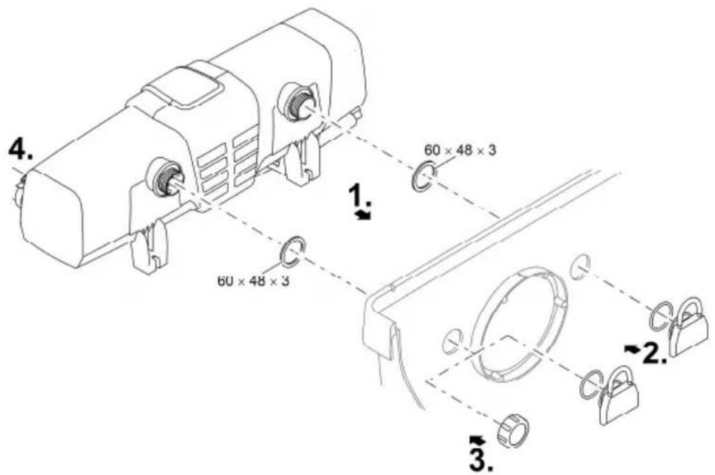
System messages
The system messages are indicated on the display. If there are several system messages pending at the same time, the oldest message is always displayed.
- The 4-digit system message is indicated on the display by two groups of two digits in succession.
- As soon as the cause has been eliminated, the system message automatically disappears.
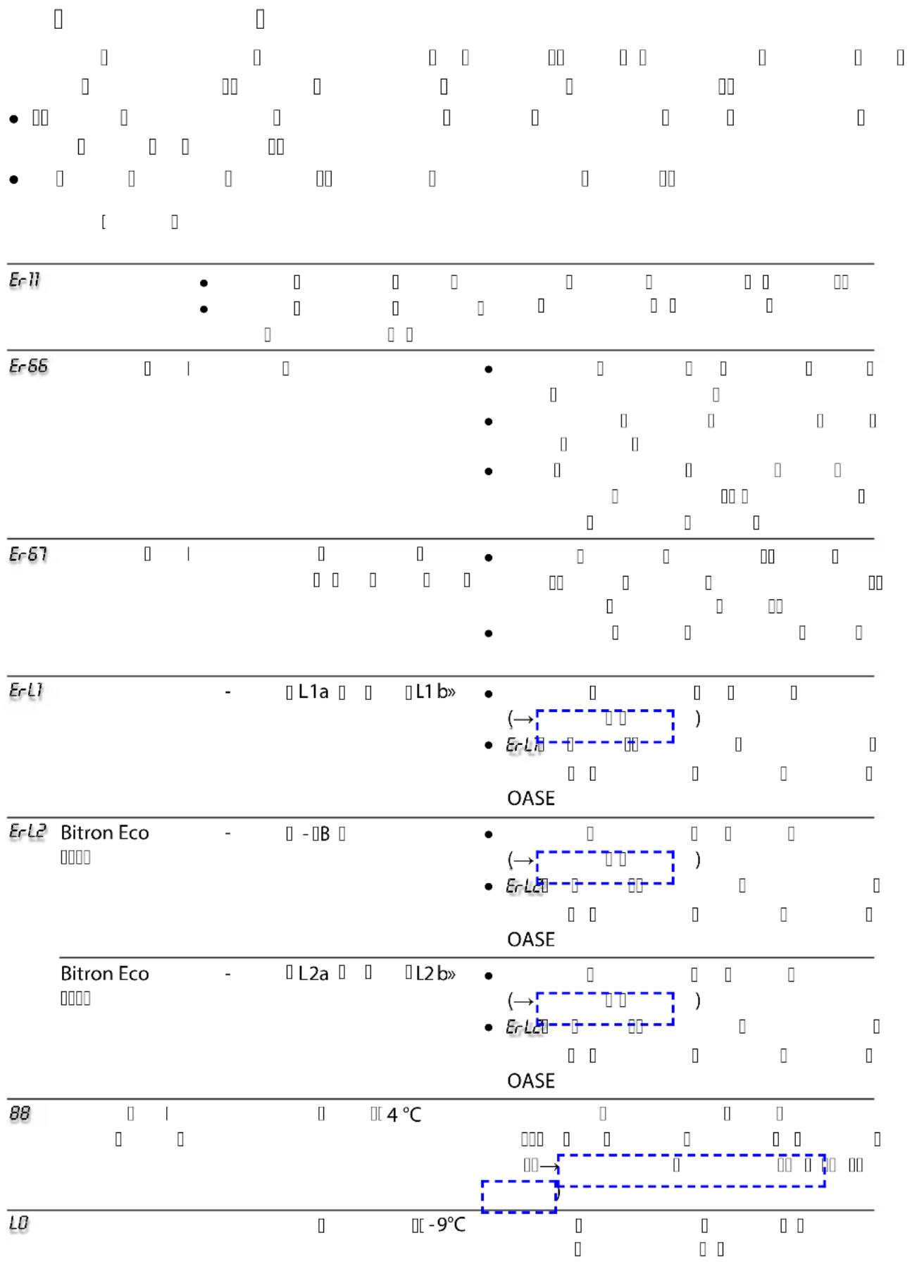
System message Cause Remedy
| Er11 | Unit head removed.Unit head is not correctly positioned in the casing. | Insert unit head into the casing, close with the engagement hook and secure with screw. | |
| Er66 | Unit has switched off. | Unit overheated. | Protect unit from direct sunlight.Ensure that water can continuously flow through the casing.After cooling down, the unit automatically switches on again and activates the last selected operating mode. |
| Er67 | Unit has switched off. | Unit temperature has been exceeded five time in succession. | Eliminate the cause of overheating (e.g. direct sun radiation, no water flow).Keep the button pressed for six seconds. |
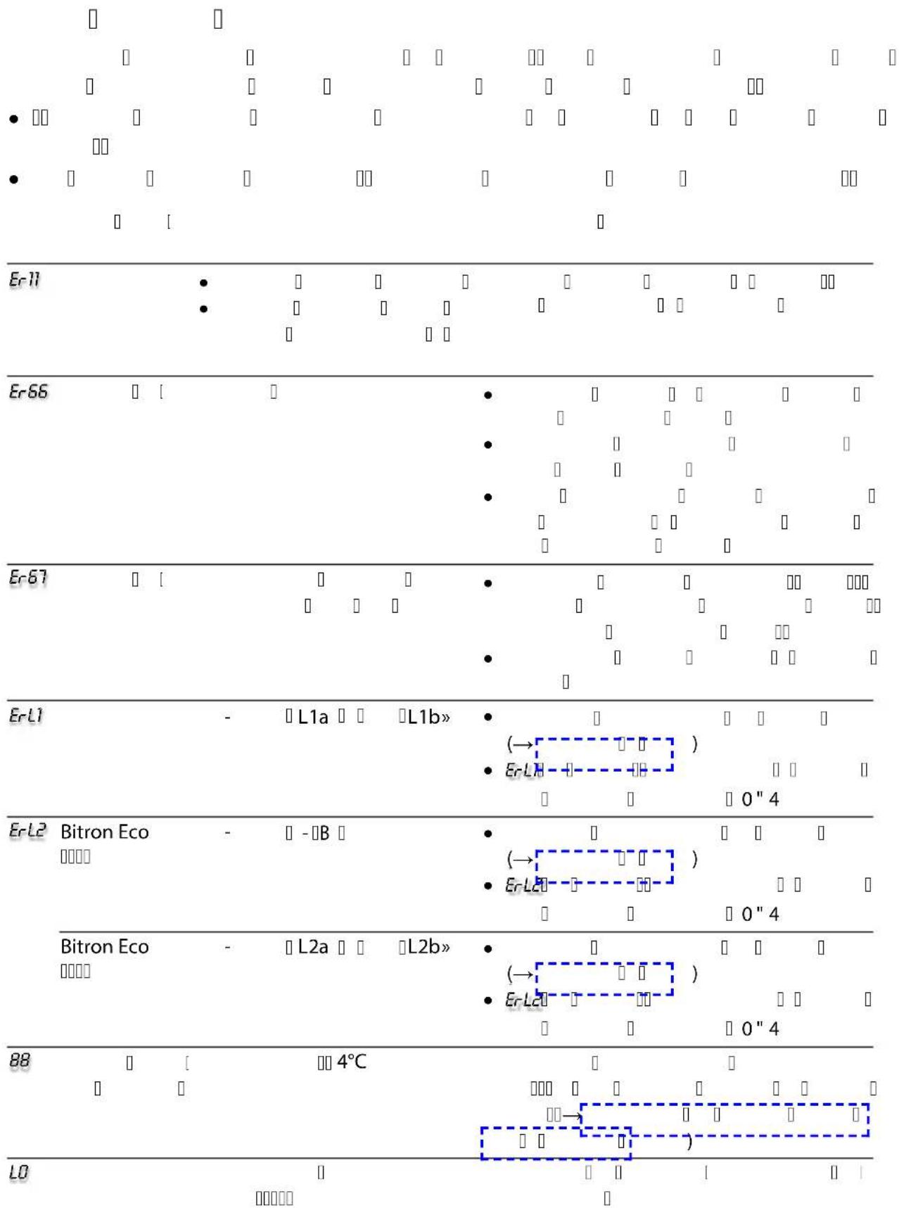
| ErL1 | UVC lamp "L1a" and/or "L1b" defective. | Replace defective UVC lamp ( Maintenance and cleaning) Er-L1 does not disappear: Contact the OASE service. | |
| ErL2 | Bitron Eco 180 W | UVC lamp "L2a" defective | Replace defective UVC lamp ( Maintenance and cleaning) Er-L2 does not disappear: Contact the OASE service. |
| Bitron Eco 240 W | UVC lamp "L2a" and/or "L2b" defective | Replace defective UVC lamp ( Maintenance and cleaning) Er-L2 does not disappear: Contact the OASE service. | |
| 88 | Temperature value flashing | Water temperature < 4 °C Ensure water temperatures of at least 4 °C or take the unit out of operation( Storage/winter protection) | |
| L0 | Ambient temperature < -9 °C Temperature display out of operation, operation is not practical. | ||
Technical data
Bitron Eco 120 W 180 W 240 W
| Supply voltage 220 - 240 V AC, | 50/60 Hz | 220 - 240 V AC, 50/60 Hz | 220 - 240 V AC, 50/60 Hz | |||
| Power consumption W 120 180 240 | ||||||
| UVC lamp wattage W 120 180 240 | ||||||
| UVC lamp type Type 60 W TC-L (UV-C) 60 W TC-L (UV-C) 60 W TC-L (UV-C) | ||||||
| Operating life h | 12000 | 12000 | 12000 | |||
| Water temperature range | Permissible | °C + 4 ... + 35 + 4 ... + 35 + 4 ... + 35 | ||||
| Temperature sen-sor | Tolerance °C | ±1 | ±1 | ±1 | ||
| Power cable | Length | m | 5 | 5 | 5 | |
| Inlet | Quantity | 1 | 1 | 1 | ||
| Connection | mm | 38 / 50 | 38 / 50 | 38 / 50 | ||
| in | 11⁄2 / 2 11⁄2 / 2 | 11⁄2 / 2 | ||||
| Outlet | Quantity | 2 | 2 | 2 | ||
| Connection | mm | 38 / 50 | 38 / 50 | 38 / 50 | ||
| in | 11⁄2 / 2 11⁄2 / 2 | 11⁄2 / 2 | ||||
| Flow rate | Max. | l/h | 50000 | 50000 | 50000 | |
| Operating pressure | Max. | bar | 1 | 1 | 1 | |
| Dimensions | L × W × H | mm | 725 × 227 × 248 | 725 × 227 × 248 | 725 × 227 × 248 | |
| Weight | Without water | kg | 7.9 | 7.9 | 8.1 | |
| with water | kg | 15.8 | 15.8 | 16.0 | ||
Wear parts
- UVC lamp, quartz glass and O ring for quartz glass
- Cleaning rotor
- Lamp holder
Disposal
NOTE
Do not dispose of this unit with household waste.
▶ Dispose of the unit by using the return system provided for this purpose.
▶ Dispose of the UVC lamp by using the return system provided for this purpose.
▶ Render the unit unusable by cutting the cables.
AVERTISSEMENT
Pos. Nombr Bitron Eco 120 W, 180 W, 240 W
BTN0008
Brancher l'entrée
BTN0009
BTN0011
BTN0003
Pos. Aantal Bitron Eco 120 W, 180 W, 240 W
Sluit de ingang aan
BTN0009
Defecte UVC-lamp vervangen
BTN0011
Opslag/overwinteren
ES
BTN0003
Pos. Canti- dad Bitron Eco 120 W, 180 W, 240 W
BTN0006
BTN0009
BTN0011
Pos. Nú-
Bitron Eco 120 W, 180 W, 240 W
mero
1 1 Vidro de cristal
2 Lâmpadas UVC
2 Bitron Eco 120W
3 Bitron Eco 180W
4 Bitron Eco 240W
PT
Ligar com a entrada
BTN0012
BTN0003
Pos. Nu- Bitron Eco 120 W, 180 W, 240 W mero
Collegare entrata
IT
BTN0006
IT
BTN0009
BTN0003
Pos. Antal Bitron Eco 120 W, 180 W, 240 W
Tilslut indgang
BTN0011
Opbevaring/overvintring
Apparatet står beskyttet mod frost (f.eks. i en garage eller carport)
BTN0003
Pos. Antall Bitron Eco 120 W, 180 W, 240 W
Koble til inngang
BTN0009
Skifte defekt UVC-lampe
BTN0003
Pos. Antal Bitron Eco 120 W, 180 W, 240 W
Ansluta ingången
Byta ut en söndrig UVC-lampa
BTN0011
BTN0003
Nro Määrä Bitron Eco 120 W, 180 W, 240 W
BTN0006
Laitepään asennus
Toimit näin:
BTN0003
BTN0011
Tárolás/Telelés
BTN0003
NÓ 『』『μ』『ü Àç』『μ』
wæiÓæÓüüü C iÔâ æßâ æiÓæÓüì Óμçìμ lμßâ À Iμ Àà
BTN0009
BTN0003
• wßì i βì i ßä æiâÓÀ Zapnutí / vypnutí)
• j □ a□sāO Ó I Óa μ □→j □ a□sāO Ó I Óa μ o
• B Ⅱ Ⅲ Ⅳ À Ⅴ μ ÓìÓaipu j Ⅵ Ⅶ äμ Ⅷ Ⅸ Ⅹ ÍBÓ Ⅺ Ⅻ ßaÓ Ó Í Í Í Í Í Í Í Í Í Í Í Í Í Í Í Í Í Í Í Í Í Í Í Í Í Í Í Í Í Í Í Í Í Í Í Í Í Í Í Í Í Í Í Í Í Í Í Í Í Í Ä
• ḥαῖ-ικόν ḣβαό Οὶ Ḡ μὶὸς Ḡ Ṁæi〔æ〕 Γὰ ḣɔː ḣαό Ḡ Ṁ Ḡ μὴὸς Ḡ Ṁæi ̄
NâÓ Ó □ □□□ |IÓ □ Ó □ I □Ó□æ □I□ Ó □
- NäμβâÓ Ó ṣæ¡¡¡ ¡Ó Ó ̄ Ó Ó ̄ I ̄ Ó¶æ ̄ ÓÓ ̄ Ó Ó À ̄ iä ̄¶ Ó â Ó ̄i¶¶æ À ̄ ̄ ̄ noty:
NäμßÓÀ Íæi β
æiμæ Í i' Þ Þ Í Í Í Í Í Í Í Í Í Í Í Í Í Í Í Í Í Í Í Í Í Í Í Í Í Í Í Í Í Í Í Í Í Í Í Í Í Í Í Í Í Í Í Í Í Í Í Í Í Í Ä
j ì□□ □ ì□□ j □□ □äμ □
• NÓ Àì À À Íäμ j à À À μ òÓ Íïï Ï ñò Æ À ÓÓ ÓÏ æÓ Ææ æè ò Àμ Íïï ì Ó títku. (→ Technické údaje)
Nä ßÓ ☐ ☐
BTN0011
Ulo ení/zazimování
Nä æiâÓÀÀ İÄI İßä äö İßä İå μÜ ÖÖ ä I, βâÓæiÓa ö NâÓ Ó βä æiâÓÀ À Ð Í ñßÓ À Ð Ó â İïμ μİμ ì ì ì βÓïÜ Ó ï ï Nä æiâÓÀÀ ì ì ñï ñßä äö İßä ì Ó ì μİæiü ö Näμ û ë æ ÿ βä æiâÓÀ ÓlìÓ ì ñnâÓ i ÿ ìμ i ì ì ì ÓliâÓ Ài βä æiâÓÀ po kození.
B æiâ Ó ì ßÓâ ÿ
Poruchy
| Porucha Nà μìòù S ì | ||
| jÓ ïÍ ïμáúó | Í¡ ïá | I ó ï jÓ ïÀ ï μ Óa Ï ï Ï μ i• ïB æiâ ï ñäæ ïüμæi ï À â ï• NaÓ ï ï Ï Ïï Ï μ i Ï• j ï Ï Ó ï ÏÓ æiâ ï ñäæ ïüμæi ï z jezírka• NaÓ ï ï Ï Ïï Ü μ i Ï• j ï Ï Ó ï |
| < Óæiì ïÍβáÓ Ï Ï À â | wÀμæi ï Ï Óæiî ïÍβáÓ ï Ï Ivody v jezírku• æi ï Ï âß ÓÍÜÄμIÜ æiÓ• NÓ μÀi ïü âß Óïæl ÏÓ Ó výkonem | |
| j Óï j ï äμ Ï Ï Ï Óæiï ï Ï Ï | j ï äμ ÿßÓ äääβáÓ Ó Ï Ï Ð μ î Ï Ï i | |
| 3ä ÊͶæ ÓÀ ï Ï μ i ÏÜ | μ i Ï ä ÊÍ' Ó¶æ ı• (→μ i Ï - - - - - - - - - - - - - - - - - - - - - - - - - - - - - - - - - - - - - - - - - - - - - - - - - - - - - - - - - - - - - - - - - - - - - - - - - - - - - - - - - - - - - - - | |
| 3ä ÊͶæ ÓÀ ïßÓ â°°Üï | • j Ïü ä ÊÍ' Ó¶æ ı• (→μ i Ï - - - - - - - - - - - - - - - - - - - - - - - - - - - - - - - - - - - - - - - - - - - - - - - - - - - - - - - - - - | |
| Nä æiâÓÀÀ ï Ï μ Ó Ï Ï | ÓÎÏ inâ- μ OFF a zvolte re im Eco | |
| 3ä ÊͶæ ÓÀ ï Ï μ i Ï' βáO íÓ ıæ ıµæiμ íáÓiÓáï íÓ • Kontrola: Vymontujte hlavu βä æiâÓÀ ï βÈ i Ï âß ó• Näμü âßö ÐÍ Ï äääääð ıßó íà ı°ßóé μîï Ï β æï āe íμ IÓ úÀi āè ı§ïiâ æ ıßáÓßó ÐÍμæiμ cího rotoru • NäμÚßóïä ïÍ' βáó μ í ı°μæ tící rotor (→μ i Ï- üü- a μ μ teho skla) | ||
| Nä æiâÓÀÜ ï Ï √ < IÍ ıßóÀ íü ıæiâ Ü wßóÀï ï ıæiâ Ü | ||
| Nä BÓÀ ıüA ∪ i! ∪ w OliâO Ài ıßä BÓÀ ∪ iâμ | ó proudu | ||
Porucha Nä μìS I
| árovka nesvítí | ☐ iμ Ó ☐IÓ☐☐ β ☐IÓæi☐ ☐ BÍ i ☐ w☐☐ β ☐IÓæi☐ ☐ Ó ☐ÀæÓ ☐ßäμ☐Óìä I☐ ☐ßä æiâÓÀμ☐ ☐äμ ☐ ☐ iμ Ó ☐I☐j☐ I☐ ☐äμ ☐ÀæÓ ☐I☐ μæß Àμ☐μì μ Ó ☐I☐ßâÓæiã ☐Iμlìn ErLlnebo ErL2. | |
| <☐☐æßÓÀ I☐æ☐ μ iâkapky | ☐æ ☐i Óä æiì I☐I Ï Óæiì☐☐☐ | • w ÓìiâÓ Àì ☐ æ☐ Ïì aèì I☐☐☐Ói☐ Ï i ☐ âÓ ÓÓ ☐æßÓÀ I☐ |
| ☐ ☐ßä æiâÓÀ ☐I ☐ À Ó i☐ NOÀμæiì ☐ âÓ ☐☐I Ï Ó I Ï Ó Ó I ☐ Ó Ï i ☐ßÓÀμæiì ☐ âÓ ☐☐j ☐ßä æiâÓÀμ☐æ ☐ i Óäμ ☐ßÓ i☐ ☐ wIßI Ï Óßä æiâÓÀ☐☐☐ Ï Ñ À À☐ Ï i☐ ☐ ä Ï Ï Ïæ Ï ☐ i☐ Ï i ☐æ ÏÓ ☐ ☐æiâ☐ ☐☐ À i ☐ ☐ßä æiâÓÀ ☐ | ||
| Zobrazení rozdílných hodnot Ó â☐☐☐ ÏÂÓ æ☐ ☐ ä I Ï Ï Ï Ï Ï Ï ☐ Ï Ï Ï Ï Ï ☐ Ï Ï Ï Ï ☐ Ï Ï Ï Ï ☐ Ï Ï Ï Ï ☐ | ||
| i Ó Óì ☐ßäμ☐ßÓ μì ☐ ☐ßä æiâÓÀ ☐OASE s ukazatelem teploty | 2æÓ μ☐æÓ ☐æi ÏßâÓ Ó Ó Ï ÏÀμI☐ßästroje s ukazatelem teploty, mohou sezobrazované teploty od sebelì it a o2°C.☐ÓßÓâ ☐ Ï Ïw☐âμì íμ☐; Óßâ â ☐ze v ech zobrazených hodnot vy-ß Ï ☐Ó☐â☐ßäμ☐ μ Ï☐ Ó ÏÓi☐æi ☐I☐ Ï Ï Ï Ï ☐ Ï Ï ☐NâÓiÓ☐ßä æiâÓÀ☐ζæi☐ Àì ☐ âI Ï ☐ßâÓip☐æ Ï Ï ☐ ä Ï ☐ | |
Systémová hlá ení
<μæß Àμæ 『Óâ¶æ æi‘ Ó 『Näμ¶æ æi‘ Ó 『æÓ¶æI¶æ 『Óâ¶v dy nejstar í hlá ení.
BTN0003
Pripojenie vstupu
- Ó â i Ó Ó ì Ó ß Ð Í Í Í Í Í Í Í Í Í Í Í Í Í Í Í Í Í Í Í Í Í Í Í Í Í Í Í Í Í Í Í Í Í Í Í Í Í Í Í Í Í Í Í Í Í Í Í Í Í Í Ä Í Í Í Í Í Í Í Í Í Í Í Í Í Í Í Í Í Í Í Í Í Í Í Í Í Í Í Í Í Í Í Í Í Í Í Í Í Í Í Í Í Í Í Í Í Í Í Í Í Â
Obsluha
Zapnutie / Vypnutie
| Prevádzkový re im 50 %: | Prevádzkový re im 75 % | Prevádzkový re im 90 % | ||||||||
| j | ☐☐☐☐☐☐☐☐☐☐☐☐☐☐☐☐☐☐☐☐☐☐☐☐☐☐☐☐☐☐☐☐☐☐☐☐☐☐☐☐☐☐☐☐☐☐☐☐☐☐☐☐☐☐☐☐☐☐☐☐☐☐☐☐☐☐☐☐☐☐☐☐☐☐☐☐☐☐☐☐☐☐☐☐☐☐☐☐☐☐☐☐☐☐☐☐☐☐☐☐ ☐☐☐☐☐☐☐☐☐☐☐☐☐☐☐☐☐☐☐☐☐☐☐☐☐☐☐☐☐☐☐☐☐☐☐☐☐☐☐☐☐☐☐☐☐☐☐☐☐☐☐☐☐☐☐☐☐☐☐☐☐☐☐☐☐☐☐☐☐☐☐☐☐☐☐☐☐☐☐☐☐☐☐☐☐☐☐☐☐☐☐☐☐☐☐☐☐☐☐☐☒☐☐☐☐☐☐☐☐☐☐☐☐☐☐☐☐☐☐☐☐☐☐☐☐☐☐☐☐☐☐☐☐☐☐☐☐☐☐☐☐☐☐☐☐☐☐☐☐☐☐☐☐☐☐☐☐☐☐☐☐☐☐☐☐☐☐☐☐☐☐☐☐☐☐☐☐☐☐☐☐☐☐☐☐☐☐☐☐☐☐☐☐☐☐☐☐☐☐☐☑☐☐☐☐☐☐☐☐☐☐☐☐☐☐☐☐☐☐☐☐☐☐☐☐☐☐☐☐☐☐☐☐☐☐☐☐☐☐☐☐☐☐☐☐☐☐☐☐☐☐☐☐☐☐☐☐☐☐☐☐☐☐☐☐☐☐☐☐☐☐☐☐☐☐☐☐☐☐☐☐☐☐☐☐☐☐☐☐☐☐☐☐☐☐☐☐☐☐☐○☐☐☐☐☐☐☐☐☐☐☐☐☐☐☐☐☐☐☐☐☐☐☐☐☐☐☐☐☐☐☐☐☐☐☐☐☐☐☐☐☐☐☐☐☐☐☐☐☐☐☐☐☐☐☐☐☐☐☐☐☐☐☐☐☐☐☐☐☐☐☐☐☐☐☐☐☐☐☐☐☐☐☐☐☐☐☐☐☐☐☐☐☐☐☐☐☐☐☐□☐☐☐☐☐☐☐☐☐☐☐☐☐☐☐☐☐☐☐☐☐☐☐☐☐☐☐☐☐☐☐☐☐☐☐☐☐☐☐☐☐☐☐☐☐☐☐☐☐☐☐☐☐☐☐☐☐☐☐☐☐☐☐☐☐☐☐☐☐☐☐☐☐☐☐☐☐☐☐☐☐☐☐☐☐☐☐☐☐☐☐☐☐☐☐☐☐☐☐ | 3.00 | 2.00 | 1.00 | 0.00 | 0.00 | 0.00 | 0.00 | 0.00 | |
| Teplota vody [°C] | Za-pnuté[h] | Vy-pnutý[h] | Doba vystave-nia iareniu[%] | Za-pnuté[h] | Vy-pnutý[h] | Doba vystave-nia iareniu[%] | Za-pnuté[h] | Vy-pnutý[h] | Doba vystave-nia iareniu[%] | |
| 4 12 72 14 12 12 50 24 12 67 | ||||||||||
| 5 ... 9 12 36 25 24 12 67 48 12 80 | ||||||||||
| 10 ... 14 12 12 50 36 12 75 96 12 89 | ||||||||||
| 15 ... 19 12 0 100 12 0 100 12 0 100 | ||||||||||
| ≥ 20 | 12 12 50 36 12 75 12 0 100 | |||||||||
j ì Ó Ïμ ÏÓ ì Ïßâ Ð Ó Ï Ó Ï
3 À ò Óæμ Í ì ï ï μ Í ì ï μ Ói Óæî ÿ j ï μ ë5 ï Ó Óâ Ïμ ïæi ÿ j ï μ ëμ j ì j ï μ ëμ ï ï æi ÿ ï ß ß μ ë Ó Ó Ó ï μ ë Ó Ó Ó Ó Ó Þ ì < ïæ ì ï æi ÿ Ù Ó Ñ Ó ï Ó Ó é é Ó Ó Ó Ó Ð Ú Ð Ó × Ú
• Nâ ælòì ìò μ ÓiÓóæî j ̄ μ̄âμ μ Õ i ̄ ïī̄ßáÓæiâ Í ù Ó ̄ μæß Àl
| Funkcia | Postupujte nasledovne Upozornenie |
| j ìïÎμ ï ÀÎ μ votnosti UVC iariviek | NÓ â i ïæi ïîî ïµ ÓÎ ïÎÎÎ pribli ne 6 s.6-miestna hodnota sa na displeji zobrazí v dy BÓæi BÌ ïßâÓæiâ Ï ï Ó ï ÓÎ ïÎÎ æ μÎÎ • wÎÎò Ó ï ß ÀÎεìÎî ïÓæiµÎæÎÎÎÎ æ ÓÎ ïßÓÎ dlh ej prestávke 3-krát zopakuje.Príklad:01-11-54---01-11-54---01-11-5401-11-54zodpovedá 11 154 hodinám zostávajúcej ivotnosti |
| j Ê Ó ïÎμ ïßÓÎÎ prevádzkových hodín | UÎ ïÎ ïÎÎßÓ â i ï ïÎæµÎ ïæ òÎ d'rÊ ïæÎ ïßÓÎÎ ï ÓÎßâ ï Ó ï ï ÓÍ prevádzkových hodín nevynuluje. NÓÎÎæ ÓÎÂÎ ïµÎÎæÎÎ ï j ïÎ µÎµ viek:wÎÓ ïÎæi ïÎ ïÎÎßÓ â i ï ÓÎæi ïÎ ï ï ïÎ âµÎ5ÎÎÎ diódy pre zobrazenie stavu UVC ï BÎÎ ïÎÎòÎÎ µ ÎÎÎa rÉz displeja nezmizne. |
μæi ìμ ïò â
UPOZORNENIE
< ßÓ Àì à â æ ì μæiμ ßâÓæiâμ ßïμμ μ ßâÓ ïÓ μ ïÓßâÓæiâμ ßÕ μî ßâ ï Óâ μî Í μ ßââ æiâÓÀ ßï ßæßÕæÓμî Ó μ âï ßâœi μÏ ßï ß Óï¹ strediu.
▶ Nâ æiâÓÀ□ ̄μæìμì □ ì□ ÓÌ □ ▪ Ï ãÓ □
SK
BTN0009
- Takto zistíte chybnú UVC iarivku v príslu nej dvojici iariviek (L1a/L1b alebo L2a/L2b): Vy- ì À Í Í Í Í Í Í j Í Í μâμ μ Í Í Í Í Í Í Í Í Í Í Í Í Í Í Í Í Í Í Í Í Í Í Í Í Í Í Í Í Í Í Í Í Í Í Í Í Í Í Í Í Í Í Í Í Í Í Í Í Í Í Ä Í Í Í Í Í Í Í Í Í Í Í Í Í Í Í Í Í Í Í Í Í Í Í Í Í Í Í Í Í Í Í Í Í Í Í Í Í Í Í Í Í Í Í Í Í Í Í Í Í Ï Æ Æ Æ Æ Æ Æ Æ Æ Æ Æ Æ Æ Æ Æ Æ Æ Æ Æ Æ Æ
-
β ἐμ ὁæ ἐ i ἐ j μμ̃ ûμ ûβÓæ i ἐ Í Í Í Í Í Í Í Í Í Í Í Í Í Í Í Í Í Í Í Í Í Í Í Í Í Í Í Í Í Í Í Í Í Í Í Í Í Í Í Í Í Í Í Í Í Í Í Í Í Í Ä
-
Ó Ó ï ï ñ ñ ñ ñ ñ ñ ñ ñ ñ ñ ñ ñ ñ ñ ñ ñ ñ ñ ñ ñ ñ ñ ñ ñ ñ ñ ñ ñ ñ ñ ñ ñ ñ ñ ñ ñ ñ ñ ñ ñ ñ ñ ñ ñ ñ ñ ñ ñ ñ ñ ï ï ï ï ï ï ï ï ï ï ï ï ï ï ï ï ï ï ï ï ï ï ï ï ï ï ï ï ï ï ï ï ï ï ï ï ï ï ï ï ï ï ï ï ï ï ï ï ï ï Ï ï ï ï ï ï ï ï ï ï ï ï ï ï ï ï ï ï ï ï ï ï ï ï ï ï ï ï ï ï ï ï ï ï ï ï ï ï ï ï ï ï ï ï ï ∞
BTN0003
Po- tevilo Bitron Eco 120 W, 180 W, 240 W stavka
| 1 1 Kremenovo steklo | |
| 2 UVC-svetilke | |
| 2 Bitron Eco 120W | |
| 3 Bitron Eco 180W | |
| 4 Bitron Eco 240W | |
| 3 1 μæiμ ἢμλάΟιόλα | |
| 4 1 Ohi je | |
| 5 1 Glava naprave s krmilno enoto | |
| Prilo en material za priklop: | |
| 6 1 Adapter 38/50 mm (11⁄2 in / 2 in) in za priklop nastavka cevi ob izhodu | |
| 7 2 Nastavek cevi 50 mm (2 in) za vhod oz. izhod | |
| 8 2 Nastavki cevi 38 mm (11⁄2 in) za vhod ali izhod | |
| 9 2 Prekrivna matica 50 mm (2 in) za pritrditev nastavka cevi (7, 8) | |
| 10 2 NÓ ἢiÓiì æiμ Óí čí čí ἠμ ἢßâ âμ ἢÓí ἢiμÓð á | |
| 11 1 j æiÓßiÓ Óið ãßÓ Óiðμæiμ I ἢäÓiÓàÀ | |
| • Mora biti uporabljana pri pretoku < 10000 l/h | |
| 12 1 kapica 38 mm (11⁄2 in) za zaprtje izhoda | |
| 13 2 NÓ ἢiÓiì æiμ Óí ἢaá ἠaí | 1 1 1 βμÓð õμìði βsì âð õ |
| 14 2 Objemka za cev 40 ... 60 mm | |
15 1 Obvodna zapora za nastavek membrane
• NÓiā 『』ßâμ ὀlì μ̵ μì â 〔À 〔ìa 〔〕ßâ iµµ Ó
• <æiì ☐ ☐âì ☐ ÓÓ Ó ÍÓ☐ ☐âìÓÁ ☐Í☐ ☐ ÙÓµ Ó ☐ÌæßáÓip Ó Óôæì☐ nje ob dobavi)
Pregled krmilnik

BTN0007
☐ <☐☐☐ Ó ☐ wìμaÀ ☐I☐☐☐☐ Ó ☐IÀ☐☐ ☐BÓiâ ☐☐Bâu ☐ÓÀ IÓÓ☐æ ☐IÀ ☐☐ [☐à☐☐☐A☐]
• 5000 □ μ □â□□□□μ□ Ó □À□
- 5□□□æ iμ□ Ó âÓ □ j □ æ iμ □æÓ□ À □ I □
- 5□□□æ iμ□ ÍÓ□ j□ æ iμ □æÓ□μ À□ I□
2 Tipka Funkcije:
• Vklop/izklop naprave (→Vklop/izklop)
• (μâ¡lμì) Ó À→ (μâ¡lμì) Ó À
- Preostala ivljenjska doba UVC-svetilk (=Ponastavitev tevca delovnih ur)
- Ponastavitev tevca delovnih ur (→ Ponastavitev tevca delovnih ur)
3 Prikazovalnik stanja UVC- svetilk
LED-prikazovalniki preostale ivljenjske dobe:
• tiri LED-diode svetijo: 9001–12000 ur
• Tri LED-diode svetijo: 6001–9000 ur
• Dve LED-diodi svetita: 3001-6000 ur
- Ena LED-dioda sveti: 1–3000 ur
- Ena LED-dioda utripa: Zamenjajte UVC-svetilke
• Vse LED-diode so ugasnjene: Vsaj ena UVC-svetilka ne deluje
4 Zaslon Prikaz stanja delovanja
- Prikaz trenutne temperature vode v °C
• Nâμ 『æpæi æ μ 『æßÓðəi 』æ 『æßÓáO』μ 』 - Prikaz preostale ivljenjske dobe UVC-svetilk (→ Ponastavitev tevca delovnih ur)
Lastnosti
Bitron Eco 120 W, čä☐k ☐ ä☐k ☐À ☐ ☐â☐ μ☐æ ÓÀ ☐Ó☐æ ☐Ì ☐ Ó☐μ ☐îâ☐À☐À☐☐ ☐ â ☐ÎÀ☐☐μÎ☐ Ó ☐ ☐ Ó Óæì Ù☐ j ☐ ☐μæìμ Íμ☐æiâÓÀ☐ ☐ßâ ßâ ☐ ☐ÎÀ ☐ ☐ µÎ☐ Ó Àμ μ ☐☐ i âμÀ ☐
• U □ ÊÓ□ □ □ μ□â¶æiμß□ ÀÓ□μ □ □ æ □ j □ æ iμ □ßÓßÓiâ □μ□ À □μÀÓÓ □μ À □μ
□â¶àÀ □À ÓßÓâ¶Ó□ ì â μÀ □ Óæ □ □â¶à À □Àμâ ā iì
• Nâ Óâ μì ìßâ ÆÀ ÓÓ Ó ÙÀ Ó Ó Ó ÊÓæ μÎÓßâμ Ó μìμ
• NÓBÓ ÍÓ 『æ』 Ó ÀÍÓ『æi』 ÀÌÀ ÍÓ Ó 『æ âμμ』 『IÓ Ó 『μÌμÀÓ』 『μÙ Ó μìÓæi in obsevanja.
• Ó Ó Ó Ê Ê Ê Ê Ê Ê Ê Ê Ê Ê Ê Ê Ê Ê Ê Ê Ê Ê Ê Ê Ê Ê Ê Ê Ê Ê Ê Ê Ê Ê Ê Ê Ê Ê Ê Ê Ê Ê Ê Ê Ê Ê Ê Ê Ê Ê Ê Ê Ê Ê Ñ Ñ Ñ Ñ Ñ Ñ Ñ Ñ Ñ Ñ Ñ Ñ Ñ Ñ Ñ Ñ Ñ Ñ Ñ Ñ Ñ Ñ Ñ Ñ Ñ Ñ Ñ Ñ Ñ Ñ Ñ Ñ Ñ Ñ Ñ Ñ Ñ Ñ Ñ Ñ Ñ Ñ Ñ Ñ Ñ Ñ Ñ Ñ Ñ Ñ Ð Ð Ð Ð Ð Ð Ð Ð Ð Ð Ð Ð Ð Ð Ð Ð Ð Ð Ð Ð Ð Ð Ð Ð Ð Ð Ð Ð Ð Ð Ð Ð Ð Ð Ð Ð Ð Ð Ð Ð Ð Ð Ð Ð Ð Ð Ð Ð Ð Ð Ú
- Naprava je primerna za vgradnjo v filtracijske sisteme OASE ProfiClear, Biotec 30 in BioTec Screenmatic.
• ኣμæìμ Ἰμ̄åÓiÓâß â ኣÌ ἐÌÓ̄μæìμ̄ â ÍÓ Óæì Ó
• ä üüìì Í Ó æ ìμ ̄æÓ̄ ̄â̄Ī μ̄μ̄ ÆÀÓ̄ μ À ÍÀæ Ó ÓÓ̄ ääǟ û
• Ⅱ iâÓlæ Ⅲßâ æiµ ⅣÌ□□ßâ□ ⅢÀ Ⅳßâ□ iµIÓ□□â Ⅱµ Ⅱ
- Za zamenjavo UVC-svetilk demonta a kremenovega stekla ni potrebna. Filtrirni sistem je lahko neprekinjeno v uporabi.
Simboli na napravi
| Preberite navodila za uporabo. | |
| <ß⤠Ӥ 1 μìµì 1ßâ 1 â 1 ÀÓ 1 | |
| <ß⤠Ӥ 1 μìµì 1ßâ 1 I 8Óæâ 1µ μæÓÌε μâ 1â 1 | |
| Nevarno UVC-sevanje. | |
| <ß⤠1Ï 1Ó â μì 1 ÓµµÀI 1 ÓæßÓ μÀæ 1Ó 8¤ 1 | |
| IP24 | <ß⤠1À 1 µì 10ßâÓïµßâ 1À 1 Ó 1µÎ¤ Óïµ 1À 1 Î 1âε 1 Ó 1 |
| p_max = 1 bar | <À 1Àµ Ó Ó À 1 Ó 1µÎî 1 1000â 1 |
| T_W = +4 - 35°C | Dovoljena vodna temperatura: od + 4 °C do + 35 °C. |
Postavitev in priklop
Priklop vhoda
Uporabite cevi, ki zdr ijo vsaj 1 bar tlaka.
▶ <ß⤠ÓÓµæiµì æ¤ ÓÓ ïÀµ ï Ó âÓ ÊßÓ
• NâμßÓâÓ ìÓµæiµ ìÓæâ æi Óßâμïâ Ó âïìµ ÏÓßïmi ÿ
- μæiμ Ó [ˈɑːb] [N β] [I] [B]
- μ Ἰμæìμ ἐ μÌ ἄ æ ἀ ÀÓ ἁ涶 μ ገ Ôâ
Redna opravila
Redno preverjajte, ali naprava deluje brezhibno. Glede na trajanje delovanja in onesna enost vode
Ó Óμì ̄æÓ Í Êâ æ Í ÊÍÓ ÓÎâÓ Ó ÿ μ À Æ ÆÀ ̄μæïμ Æ ÆÓ Ê ÆÀ ÆÓæï ÆÓ Ææï a pregledovati napravo. Bodite pozorni na:
- Stanje naprave na krmilniku. (→Pregled krmilnik)
• Ó ÓÀ μæìμ Í ûâÓiÓâÀj μ ÿ ì ÓÎâÓ À Ó Óïü ñ Ó æiâÎμì ÿ ÓÎî prave.(→ Snemanje glave naprave)
— Uporabite epno svetilko za la ji pregled.
Snemanje glave naprave
PREVIDNO
ìā μÀÓ μÒÓæ ǜÀ jì ǜàìμò ò ÓBÓ Ó À òÓμμì Ó Ó
BTN0006
- wǒsÓā μ æμālǐóæμ lóð Ó Ó ï Ó Ó ïæÓ j ï æ ïü ïâ ló ï ï ïóæμ ïæ ï
- <Óæμ ኡæ iμ ኡßâ μ ἸÓßâμìμæÌμì ኡÌⱼ j æ iμ ኡì Ó ኡæ ኡæ ÓµÀÓæ I Iæ æ

BTN0002
μ ìÀ ìÀ ïâ ì ïæi
PREVIDNO
3â ìÓ Óæi Óμì j ñ âìμπæ Ï Ó Ó μìμìßÓ âÓμì û ìμì
▶ Ó μì ìßâ μ Íμ ñ Ó Ïïj j ïµæiµ ÿ ïæ ÿμ Ó ì i ì æÎμ ÏÓ Ó ï Þ
▶ (Ó μ□□Àì □æ □iâ æ À□À □ □â□ □μì□ μìâμ □ßâ μ Ó □□ßâ ßâ □μì □ Ó □æì □
NASVET
<ß⤠æ □ ÓßÓ Ó À □ ÆÀ ÏÓ Ð ßÓï Ðßâμì □ ÏÎ Ï Ó ßßâ μÌÀ ÏðßâßÓâïµ □ æ ÏÓ õ□ ÆÀ Ïßâ ÏÓ Ð Ï Ï Ð ßßâ μÌÀ Ï□ Ó μ ìï Ïßâ Ó Þ□ûâ¤ Ó μìvodnemu udaru.
▶(Óß¼<Àßâ Àμ À μì ıâß Ó ıïó ßâµì ıæ ÍÑâµ ßÓâµü μ iâµâÏ æµæì À μì μ iâµâïµæµæi
▶ j Óß <Àßâ ÀÓ ßâμì 『ßÓâÎμ』 æ ìμÎÎÎÎÓ À μì 『âß』 Ó Nâμ BÓâε μ iâμâÏ æ ÙÀ À μì 『IÀ IÀ
▶ Po elji lahko pred vhod namestite zaporni zasun.
Predpogoj:
- Glava naprave je sneta. (→Snemanje glave naprave)
- NÓ Ó Ó ïÓμ Ó ïÓæßâæ ïÓ ã Ï Ó Óæi Ó ã ÙÀÀì
- Sprostite zaporni vijak in potegnite kremenovo steklo z O-tesnilom iz pokrova ohi ja.
- Bμæiμì ⅢB i æIμ ÓμI□ ⅣI□ Ⅳæiμì □ □ ⅣæiÀÓ□B□U□ò i μ □□ ⅢI□ÎàÓ□μ Ó□ cčć ð NÓ Ó Ó O-tesnilo zamenjajte.
- Kremenovo steklo z O-tesnilom postavite na pokrov ohi ja in zaporni vijak do konca privijte.
- B i ælμ ÓßÓi ìμì ̄aÓ̄b̄sâ ßà μì òμ̂μâ̄À Óæī Ó õæiμ̄Î̄â Ï Ê
- wßÓâìμμÀæ Óâàæ μ ÊÓ Ææ Óμìμ ÿïæßâÓiÙ Ïbâμ â ÏBÓ âÓ ÏÓ μ Àïïμ ìti v ohi je.
- Nâ âμì ÓÎâÎÎÓÎßâÓ μ ÎÎεæïµ Í ÎÎâÓïÓâÀÎÎÎÓ Í Í µ ÍæïâÎ Í μÎÎÎÓïâε ÍßÓ â μÎ
- Ⅱ À Ⅲ ßâÓ μ Ⅳ Óâ□ À Ïæ Ⅲμæiμ ÍμâÓiÓâ□ì Ó□ âìμ□ Ⅳ Óâ□ì □ □□ □ ÍÀ□ìμ
BTN0011
U □ μ □ IÀ Nâ μ Ó IÀ
□ßâ□ □À □ □ μì ì□ßâ □ â □ ÀÓ□ ìßâ □ □ ì□ μ□□ μÓ □ A ö□

BTN0003
Poz. Koli- Bitron Eco 120 W, 180 W, 240 W
| μI | |
| 1 1 Kvarcno staklo | |
| 2 UVC svjetiljke | |
| 2 Bitron Eco 120 W | |
| 3 Bitron Eco 180 W | |
| 4 Bitron Eco 240 W | |
| 3 1 ÓiÓá☐ ☐☐☐μ ☐ IÀ ☐ | |
| 4 1 3 ☐μ i ☐ | |
| 5 1 " ☐ ☐ ☐ â ☐À☐☐æ☐ Bâ☐ À☐☐ Ó ☐À μI☐☐Ó ☐ | |
| Ó ☐I☐☐ß☐ i☐☐☐æ☐ßâμ À ☐I☐ ☐ ☐ì âμÀ☐ Ó ☐ | |
| 6 1 ☐ ☐Si â☐çă ā☐ ☐ ☐ ☐☐☐☐☐☐☐ßâμ À ☐μ ☐IÀ ☐ßâμ À ☐I☐ ☐ ☐☐☐âμÀ Ó☐☐☐☐☐ ☐ ☐ | |
| 7 2 Nâμ À ☐I☐☐☐☐ ☐☐☐âμÀ Ó☐ ä☐ ☐ ☐☐☐☐☐ ☐ ☐ ☐μ ☐☐☐ ☐ | |
| 8 2 Nâμ À ☐I☐ ☐ ☐☐☐âμÀ Ó☐çă☐ ☐ ☐☐☐☐☐ ☐ ☐ ☐μ ☐☐☐ ☐ | |
| 9 2 UBÓÀI☐☐ ☐i☐☐☐ ä☐ ☐ ☐☐☐☐☐ ☐☐ßâμ☐ â ☐μ ☐IÀ ☐ßâμ À ☐I☐ ☐ ☐☐☐âμÀ Ó☐óć ☐čó☐ | |
| 10 2 Plosnata brtva 57 × 48 × 3 mm za spojnu maticu (9) | |
| 11 1 ☐ I☐☐ ☐ I☐☐☐ ☐☐ßÓ â i☐IÀ ☐áOiÓá☐☐ ☐☐☐☐☐ ☐IÀ ☐ | |
| • ; Óá☐☐æ ☐ iI i☐☐ ☐ ☐ßâμ☐ Ó μ☐☐☐ ☐☐ßáOiÓ ☐ ☐ ääää☐ ☐ | |
| 12 1 w☐ßÓáI☐☐ßÓ Óß☐☐☐çă☐ ☐ ☐☐☐☐☐ ☐ ☐ ☐á☐IÀ ☐☐ ☐ | |
| 13 2 Plosnata brtva 45 × 33 × 3 mm za zaporni poklopac (12) i adapter (6) | |
| 14 2 Crijevna obujmica 40 ... 60 mm |
15 1 NÓ Óß□□ μ Ó Ó □□ □□ â □□ □ □â□ì □
- Potreban prilikom monta e na filtar, kada treba zatvoriti izlaz
• Ⅲā Ⅲ□□ Ⅲālì Ⅲæ ⅢālìÓ Ⅲ□□ μ Ó Ó Ⅲ□□ μæ Ⅲμ Ⅲlìæ βāÓi Ⅲ□□æiìÀ ⅢBâμ likom isporuke)
HR
Nâ Ïsâ Æ Ó Ó æ æi Þ

BTN0007
Nâμ À μ ÊÀ □ □
- NÓ Óß□□□ μ Ó Ó □□ Ó □æ □ì□□ I iμ□□□ â □□□ μ Ó Ó □æ □Ó □À ìÓ □ßÓ Ó □À □
- ìμì ̃ ˆ ̃ μ Ó Ó ̃ μ ̃ μ̃ ̃ ˆ μì ̃ ̃ ælÓ Ó Ù ̃ À i ̃ μ
- [â ] μ Ó Ó [À ] μ æμâ]
-
Provedite izlaze s plosnatim brtvama kroz otvore u stjenci spremnika u razdjelnik.
-
NâÓß æì ̄ μÀ ̄ßâμ̄ âæìμì ̄Ì̄μ̄ ̄ μ̄ ̄ì ìμì ̄μ ̄â Ó ̄
-
Nâμ À μì μìaÓìB β μ iâμàÀ → Nāμ À μ À

HR
BTN0016
Stavljanje u pogon
NAPOMENA
â Ààæ ì Ó Þ i îµiµ Óæ ñÓ ì Ó ÐÎμ ÿ ÑÓ ÿßâ μì Þißâ æœ ÏßÓâÎμ ÿ μ Êa μßâ μ ì Ó ÞÓ Úîµ âì ÓiâÀIÓßÓ ÏÀ ï Ï ÑÓ ÿ Ü Ó Ï¿â¤ò Ó Íµ Ïãô
▶ (æ À μ ÍÀ <ÀßâμÀ μæ À μì β β ÍßÓiÓ ÿ Í Ôμì ÿ ÿ ⤠ÿ Ó â ÆÀâ ÿ μü za filtriranje, najprije stavite sustav za filtriranje izvan pogona.
▶ À μ ἐÀ < ἀßâμÀ ὁì Óâμì ἐì ἀ⶧ÓiÓ ἐ À μì βß β ἐÓ̄ â ἀⶵæ; filtriranje, sustav za filtriranje posljednji stavite u pogon.
▶ Alternativno instalirati zaporni kliznik ispred ulaza.
① Novim filtrima potrebno je oko 3 do 4 tjedna da se biologija potpuno obnovi. Tijekom tog ra- ÓÀμμβâμì ß âì ûÓ Þ ä Ë Í Æ Ê Êâ μ ÏÀ μ iâ ñ ñÓ ãa ßÓiâ ÏÓµ ÏÀ μ iâ
- Prilikom uporabe filtarskih startera, lijekova ili sredstva za njegovanje jezerca neka UVC ßâÓµæi______ µæ À ⅠⅡⅠÀ ⅡÀ Ⅲa Ⅳæ̅μμ Ⅴ ÓÌ ⅥμÓæ ⅦμÓÀ Ó ÐÀ Ⅷμ Ⅸæâ a
① Nâμ μ Ó ṣμæßÓâ ̄ â ̄À̄À̄ μæ À ̄ Ī<̄¶æ Óì ̄æ ̄ßâμ ̄ À OFF.
- 3□ □□À □æ æi□ □À â□□□IÓ □æ□□ â□□ IÀ □ □ßÓ□μì □□Àâ□μÀ □□ Ól̩a □æ□μ□ □ Ó□μ□ prije mogla razviti stabilna biologija jezerca.
• ʊɪˈIÀ ɑ̂ ɑ̃ ʌ̃ ɪ̃ ɔ̃ ɑ̃ ɑ̃ ɔ̃ ɑ̃ ɑ̃ ɑ̃ ɑ̃ ɑ̃ ɑ̃ ɑ̃ ɑ̃ ɑ̃ ɑ̃ ɑ̃ ɑ̃ ɑ̃ ɑ̃ ɑ̃ ɑ̃ ɑ̃ ɑ̃ ɑ̃ ɑ̃ ɑ̃ ɑ̃ ɑ̃ ɑ̃ ɑ̃ ɒ̃
• (æßâÎÓæïîâÓiÓâÎε ÎÀ j μ ÎÎÎÔìîâÓ Ó ÀÎΠÀ ÎÎΠÀ ÎÎΠâ ÀÎΠ– ÔÎÎûâÎÀ ÎÎΠà ÀÎΠ– ÔÎÎûâÎÀ ÎÎΠ– ÔÎÎûâÎÀ ÎÎΠ– ÔÎÎûâÎÀ ÎÎΠ– ÔÎÎûâÎÀ ÎÎΠ– ÔÎÎûâÎÀ ÎÎΠ– ÔÎÎûâÎÀ ÎÎΠ– ÔÎÎûâÎÀ ÎÎΠ– ÔÎÎûâÎÀ ÎÎΠ– ÔÎÎûâÎÀ ÎÎΠ-
BTN0006
ÓlìμâÀ □ □ □ â À□□
NÓæi βμì ìÏàæ À μμÏϵï
-
N□ Àμ Ó□ i□ ìμì □ □ □ â □À□□ □ □μì □
-
! μ æμâÀì □ □ □ â À□□ æ Ó□IÓ □ Ó □
-
Nâμ□ âæiμì □æμ âìÓælμ□ μÀ□ □μ□ □ì ìμì □ □□â Ó □
HR
BTN0009
BTN0003
Poz. Canti- tate Bitron Eco 120 W, 180 W, 240 W
Clor liber 0.3 ... 0.6 mg/l < 0.3 mg/l
☐ Óⶠì¶Ó β μ¶ < 0.2 mg/l -
Ólðμì i Óá âμ < 200 mg/l -
ÓIðμì i æ â - < 3.5 %
Temperatura apei +4 ... +30 °C +4 ... +25 °C
BTN0009
RO
ì Ó μâ βμμ j ì
• ìμ μ ὅμÌ ὂμὶ ὁμὸ ὁμὸ ὁiâː μÓ ì ὂ j ὁμὸ ὁáôæμ ὁó μ ὁà ὂ μß ì â ὁóâ æß ì ὂ ì Ó β ὁɔ̃ ὁµß ὁ→Date tehn!ce)
ÓI μμμὶ ἀæâ
^1 i
| Becul nu se aprinde +ììa â ß â ☐ ☐æμ âòì☐☐☐☐☐☐☐☐☐☐☐☐☐☐☐☐☐☐☐☐☐☐☐☐☐☐☐☐☐☐☐☐☐☐☐☐☐☐☐☐☐☐☐☐☐☐☐☐☐☐☐☐☐☐☐☐☐☐☐☐☐☐☐☐☐☐☐☐☐☐☐☐☐☐☐☐☐☐☐☐☐☐☐☐☐☐☐☐☐☐☐☐☐☐☐☐☐☐☐☐ ☐☐☐☐☐☐☐☐☐☐☐☐☐☐☐☐☐☐☐☐☐☐☐☐☐☐☐☐☐☐☐☐☐☐☐☐☐☐☐☐☐☐☐☐☐☐☐☐☐☐☐☐☐☐☐☐☐☐☐☐☐☐☐☐☐☐☐☐☐☐☐☐☐☐☐☐☐☐☐☐☐☐☐☐☐☐☐☐☐☐☐☐☐☐☐☐☐☐☐☐☑☐☐☐☐☐☐☐☐☐☐☐☐☐☐☐☐☐☐☐☐☐☐☐☐☐☐☐☐☐☐☐☐☐☐☐☐☐☐☐☐☐☐☐☐☐☐☐☐☐☐☐☐☐☐☐☐☐☐☐☐☐☐☐☐☐☐☐☐☐☐☐☐☐☐☐☐☐☐☐☐☐☐☐☐☐☐☐☐☐☐☐☐☐☐☐☐☐☐☐☒☐☐☐☐☐☐☐☐☐☐☐☐☐☐☐☐☐☐☐☐☐☐☐☐☐☐☐☐☐☐☐☐☐☐☐☐☐☐☐☐☐☐☐☐☐☐☐☐☐☐☐☐☐☐☐☐☐☐☐☐☐☐☐☐☐☐☐☐☐☐☐☐☐☐☐☐☐☐☐☐☐☐☐☐☐☐☐☐☐☐☐☐☐☐☐☐☐☐☐□☐☐☐☐☐☐☐☐☐☐☐☐☐☐☐☐☐☐☐☐☐☐☐☐☐☐☐☐☐☐☐☐☐☐☐☐☐☐☐☐☐☐☐☐☐☐☐☐☐☐☐☐☐☐☐☐☐☐☐☐☐☐☐☐☐☐☐☐☐☐☐☐☐☐☐☐☐☐☐☐☐☐☐☐☐☐☐☐☐☐☐☐☐☐☐☐☐☐☐○☐☐☐☐☐☐☐☐☐☐☐☐☐☐☐☐☐☐☐☐☐☐☐☐☐☐☐☐☐☐☐☐☐☐☐☐☐☐☐☐☐☐☐☐☐☐☐☐☐☐☐☐☐☐☐☐☐☐☐☐☐☐☐☐☐☐☐☐☐☐☐☐☐☐☐☐☐☐☐☐☐☐☐☐☐☐☐☐☐☐☐☐☐☐☐☐☐☐☐ |
RO
Mesaje-sistem
; æÀ æμæì ïè μ ì β μæß ï+ì ï ï μ ïÓâ ïÀ æμæì ïÓÎÓ μì ï ï μ ïìÓï ï ï ï æÀ ï ï ï μ ï μ ï
• ; æÀ æμæì ☐ ☐ ☐BÓ μïμμ☐ ☐ μµμ μ ☐iæ ☐ æμ ☐ßâμì☐☐☐ ☐ Ó ☐☐☐μ â ☐ß ☐ μæß☐ ☐
• ( μἰἰἰἰ ኀːː æi ኀː iì âɪɪː æÀ æμæi ኀæ ኀæiμì ኀ iÓ ኀ i
Mesaj-sistem 📄 📄 Remediere
| Er-11 | ▪▪▪▪▪▪▪▪▪▪▪▪▪▪▪▪▪▪▪▪▪▪▪▪▪▪▪▪▪▪▪▪▪▪▪▪▪▪▪▪▪▪▪▪▪▪▪▪▪▪▪▪▪▪▪▪▪▪▪▪▪▪▪▪▪▪▪▪▪▪▪▪▪▪▪▪▪▪▪▪▪▪▪▪▪▪▪▪▪▪▪▪▪▪▪▪▪▪▪▪□▪▪▪▪▪▪▪▪▪▪▪▪▪▪▪▪▪▪▪▪▪▪▪▪▪▪▪▪▪▪▪▪▪▪▪▪▪▪▪▪▪▪▪▪▪▪▪▪▪▪▪▪▪▪▪▪▪▪▪▪▪▪▪▪▪▪▪▪▪▪▪▪▪▪▪▪▪▪▪▪▪▪▪▪▪▪▪▪▪▪▪▪▪▪▪▪▪▪▪ | ||
| Er-55 | Aparatul s-a de-conectat | ▪▪▪▪▪▪▪▪▪▪▪▪▪▪▪▪▪▪▪▪▪▪▪▪▪▪▪▪▪▪▪▪▪▪▪▪▪▪▪▪▪▪▪▪▪▪▪▪▪▪▪▪▪▪▪▪▪▪▪▪▪▪▪▪▪▪▪▪▪▪▪▪▪▪▪▪▪▪▪▪▪▪▪▪▪▪▪▪▪▪▪▪▪▪▪▪▪▪□ | ▪▪▪▪▪▪▪▪▪▪▪▪▪▪▪▪▪▪▪▪▪▪▪▪▪▪▪▪▪▪▪▪▪▪▪▪▪▪▪▪▪▪▪▪▪▪▪▪▪▪▪▪▪▪▪▪▪▪▪▪▪▪▪▪▪▪▪▪▪▪▪▪▪▪▪▪▪▪▪▪▪▪▪▪▪▪▪▪▪▪▪▪▪▪▪▪▪▪: |
| Er-67 | Aparatul s-a de-conectat | Temperatura aparatului a fost de-β▪μ▪▪▪▪▪▪▪▪▪▪▪▪▪▪▪▪▪▪▪▪▪▪▪▪▪▪▪▪▪▪▪▪▪▪▪▪▪▪▪▪▪▪▪▪▪▪▪▪▪▪▪▪▪▪▪▪▪▪▪▪▪▪▪▪▪▪▪▪▪▪▪▪▪▪▪▪▪▪▪▪▪▪▪▪▪▪▪▪▪▪▪▪▪▪▪▪▪▪▪: | ▪▪▪▪▪▪▪▪▪▪▪▪▪▪▪▪▪▪▪▪▪▪▪▪▪▪▪▪▪▪▪▪▪▪▪▪▪▪▪▪▪▪▪▪▪▪▪▪▪▪▪▪▪▪▪▪▪▪▪▪▪▪▪▪▪▪▪▪▪▪▪▪▪▪▪▪▪▪▪▪▪▪▪▪▪▪▪▪▪▪▪▪▪▪▪▪▪▪° |
| Er-L1 | 5□ βμ □ j □□ 5 □□ μ □æ □ 5 □□fecte | ▪▪▪▪▪▪▪▪▪▪▪▪▪▪▪▪▪▪▪▪▪▪▪▪▪▪▪▪▪▪▪▪▪▪▪▪▪▪▪▪▪▪▪▪▪▪▪▪▪▪▪▪▪▪▪▪▪▪▪▪▪▪▪▪▪▪▪▪▪▪▪▪▪▪▪▪▪▪▪▪▪▪▪▪▪▪▪▪▪▪▪▪▪▪▪▪▪▪ | |
| Er-L2 | Bitron Eco180 W | 5□ β▪▪ j □□5 □□ □□□ | ▪▪▪▪▪▪▪▪▪▪▪▪▪▪▪▪▪▪▪▪▪▪▪▪▪▪▪▪▪▪▪▪▪▪▪▪▪▪▪▪▪▪▪▪▪▪▪▪▪▪▪▪▪▪▪▪▪▪▪▪▪▪▪▪▪▪▪▪▪▪▪▪▪▪▪▪▪▪▪▪▪▪▪▪▪▪▪▪▪▪▪▪▪▪▪▪▪ |
| ▪▪▪▪▪▪▪▪▪▪▪▪▪▪▪▪▪▪▪▪▪▪▪▪▪▪▪▪▪▪▪▪▪▪▪▪▪▪▪▪▪▪▪▪▪▪▪▪▪▪▪▪▪▪▪▪▪▪▪▪▪▪▪▪▪▪▪▪▪▪▪▪▪▪▪▪▪▪▪▪▪▪▪▪▪▪▪▪▪▪▪▪▪▪▪▪▪▪◎ | |||
| Bitron Eco240 W | 5□ βμ □ j □□5 □□ μ □æ □□5 □□fecte | ▪▪▪▪▪▪▪▪▪▪▪▪▪▪▪▪▪▪▪▪▪▪▪▪▪▪▪▪▪▪▪▪▪▪▪▪▪▪▪▪▪▪▪▪▪▪▪▪▪▪▪▪▪▪▪▪▪▪▪▪▪▪▪▪▪▪▪▪▪▪▪▪▪▪▪▪▪▪▪▪▪▪▪▪▪▪▪▪▪▪▪□ | |
| 88 | Valoarea tem-peraturii se aprinde intermi-tent | Temperatura apei < 4 °C □æμ | ▪▪▪▪▪▪▪▪▪▪▪▪▪▪▪▪▪▪▪▪▪▪▪▪▪▪▪▪▪▪▪▪▪▪▪▪▪▪▪▪▪▪▪▪▪▪▪▪▪▪▪▪▪▪▪▪▪▪▪▪▪▪▪▪▪▪▪▪▪▪▪▪▪▪▪▪▪▪▪▪▪▪▪▪▪▪▪▪▪▪▪▪▪▪▪▪▪▪・ |
| L0 | β â¤i ⤤¤ □µ¤i¤¤ □ □ □ | (ì 줤iÓâ □ lì β â¤i ⤤ÆÓæø μlì ìlìúì ìlìúì ìlìúì ìlìúì ìlìúì ìlìúì ìlìúì ìlìúì ìlìúì ìlìúì ìlìúì ìlìúì ìlìúì ìlìúì ìlìúì ìlìúì ìlìúì ì lì | |
Date tehnice
Bitron Eco 120 W 180 W 240 W
BG
BTN0003
| Bitron Eco 120 W, 180 W, 240 W | ||||||||||||
| 1 | 1 | |||||||||||
| 2 | UVC- | |||||||||||
| 2 | Bitron Eco 120W | |||||||||||
| 3 | Bitron Eco 180W | |||||||||||
| 4 | Bitron Eco 240W | |||||||||||
| 3 | 1 | |||||||||||
| 4 | 1 | |||||||||||
| 5 | 1 | |||||||||||
| 6 | 1 | |||||||||||
| 7 | 2 | |||||||||||
| 8 | 2 | |||||||||||
| 9 | 2 | |||||||||||
| 10 | 2 | |||||||||||
| 11 | 1 | |||||||||||
| 12 | 1 | |||||||||||
| 13 | 2 | |||||||||||
| 14 | 2 | |||||||||||
| 15 | 1 | |||||||||||
BTN0007
flowchart
graph TD
    A["Input Data"] --> B{Condition 1}
    B -->|Yes| C["Process Step 1"]
    B -->|No| D["Process Step 2"]
    C --> E{Condition 2}
    D --> F{Condition 3}
    E --> G["Output Data"]
    F --> H["Output Data"]
    G --> I["Final Output"]
    H --> I
    style A fill:#f9f,stroke:#333
    style I fill:#bbf,stroke:#333
BG
![IP24 pmax = 1 bar Tw = +4 - 35°C □ □ □ □ 67 - [ ] □ □ □ □ □ □ □ 4°C □ 35°C.](/content/2026/04/650336/images/ae00d033cceb6a2bc8ec47b27beec30e730414206b9bacdeda335573f2279179.jpg)
other
| pH Range | Value | Percentage | |----------|-------|----------| | < 0.3 | 7.2 | 7.6 | | < 0.3 | 7.5 | 8.5 | | < 0.3 | 0.3 | 0.6 | | < 0.3 | < 0.3 | - | | < 0.3 | < 0.2 | - | | < 0.3 | < 200 | - | | < 0.3 | - | < 3,5% | | +4 | +4 | +30°C | | +4 | +4 | +25°C | | +4 | - | - | | ≥ 2 m | - | - | | ≥ 2 m | - | - | | ≥ 2 m | - | - | | ≥ 2 m | - | - | | ≥ 2 m | - | - | | ≥ 2 m | - | - | | ≥ 2 m | - | - | | ≥ 2 m | - | - | | ≤ 2 m | - | - | | ≤ 2 m | - | - | | ≤ 2 m | - | - | | ≤ 2 m | - | - | | ≤ 2 m | - | - | | ≤ 2 m | - | - | | ≤ 2 m | - | - | | ≤ 2 m | - | < 3,5% | | ≤ 2 m | - | - | | ≤ 2 m | - | - | | ≤ 2 m | - | - | | ≤ 2 m | - | - | | ≤ 2 m | - | - | | ≤ 2 m | - | - | | ≤ 2 m | - | - | | ≤ 2 m | < 3,5% | - | | ≤ 2 m | < 3,5% | - | | ≤ 2 m | < 3,5% | - | | ≤ 2 m | < 3,5% | - | | ≤ 2 m | < 3,5% | - | | ≤ 2 m | < 3,5% | - | | ≤ 2 m (Rightarrow) | - | Yes | | ≤ 2 m (Rightarrow) | - | No | | ≤ 2 m (Rightarrow) | - | Yes | | ≤ 2 m (Rightarrow) | - | No | | ≤ 2 m (Rightarrow) | - | Yes | | ≤ 2 m (Rightarrow) | - | No | | ≤ 2 m (Rightarrow) | - | Yes | | ≤ 2 m (Rightarrow) | - | No | | ≤ 2 m (Rightarrow) / ≤ 2 m (Rightarrow) / ≤ 3m (Rightarrow) / ≤ 4m (Rightarrow) / ≤ 5m (Rightarrow) / ≤ 6m (Rightarrow) / ≤ 7m (Rightarrow) / ≤ 8m (Rightarrow) / ≤ 9m (Rightarrow) / ≤ 10m (Rightarrow) / ≤ 11m (Rightarrow) / ≤ 12m (Rightarrow) / ≤ 13m (Rightarrow) / ≤ 14m (Rightarrow) / ≤ 15m (Rightarrow) / ≤ 16m (Rightarrow) / ≤ 17m (Rightarrow) / ≤ 18m (Rightarrow) / ≤ 19m (Rightarrow) / ≤ 20m (Rightarrow) / ≤ 21m (Rightarrow) / ≤ 22m (Rightarrow) / ≤ 23m (Rightarrow) / ≤ 24m (Rightarrow) / ≤ 25m (Rightarrow) / ≤ 26m (Rightarrow) / ≤ 27m (Rightarrow) / ≤ 28m (Rightarrow) / ≤ 29m (Rightarrow) / ≤ 30m (Rightarrow) / ≤ 31m (Rightarrow) / ≤ 32m (Rightarrow) / ≤ 33m (Rightarrow) / ≤ 34m (Rightarrow) / ≤ 35m (Rightarrow) / ≤ 36m (Rightarrow) / ≤ 37m (Rightarrow) / ≤ 38m (Rightarrow) / ≤ 39m (Rightarrow) / ≤ 40m (Rightarrow) / ≤ 41m (Rightarrow) / ≤ 42m (Rightarrow) / ≤ 43m (Rightarrow) / ≤ 44m (Rightarrow) / ≤ 45m (Rightarrow) / ≤ 46m (Rightarrow) / ≤ 47m (Rightarrow) / ≤ 48m (Rightarrow) / ≤ 49m (Rightarrow) / ≤ 50m (Rightarrow) / ≤ 51m (Rightarrow) / ≤ 52m (Rightarrow) / ≤ 53m (Rightarrow) / ≤ 54m (Rightarrow) / ≤ 55m (Rightarrow) / ≤ 56m (Rightarrow) / ≤ 57m (Rightarrow) / ≤ 58m (Rightarrow) / ≤ 59m (Rightarrow) / ≤ 60m (Rightarrow) / ≤ 61m (Rightarrow) / ≤ 62m (Rightarrow) / ≤ 63m (Rightarrow) / ≤ 64m (Rightarrow) / ≤ 65m (Rightarrow) / ≤ 66m (Rightarrow) / ≤ 67m (Rightarrow) / ≤ 68m (Rightarrow) / ≤ 69m (Rightarrow) / ≤ 70m (Rightarrow) / ≤ 71m (Rightarrow) / ≤ 72m (Rightarrow) / ≤ 73m (Rightarrow) / ≤ 74m (Rightarrow) / ≤ 75m (Rightarrow) / ≤ 76m (Rightarrow) / ≤ 77m (Rightarrow) / ≤ 78m (Rightarrow) / ≤ 79m (Rightarrow) / ≤ 80m (Rightarrow) / ≤ 81m (Rightarrow) / ≤ 82m (Rightarrow) / ≤ 83m (Rightarrow) / ≤ 84m (Rightarrow) / ≤ 85m (Rightarrow) / ≤ 86m (Rightarrow) / ≤ 87m (Rightarrow) / ≤ 88m (Rightarrow) / ≤ 89m (Rightarrow) / ≤ 90m (Rightarrow) / ≤ 91m (Rightarrow) / ≤ 92m (Rightarrow) / ≤ 93m (Rightarrow) / ≤ 94m (Rightarrow) / ≤ 95m (Rightarrow) / ≤ 96m (Rightarrow) / ≤ 97m (Rightarrow) / ≤ 98m (Rightarrow) / ≤ 99m (Rightarrow) / > | | | | | | | | | | | | | | | | | | | | | | | | | | | | | | | | | | | | | | | | | | | | | | | | | | | | | | | | | | | | | | | | | | | | | | | | | | | | | | | | | | | | | | | | | | | | | | | | | | | | | | | | | | | | | | | | | | | | | | | [Note: The provided code contains the actual output of the image content in the table above and above is not explicitly labeled.] [Error: The image content is not explicitly labeled as 'pH-' or 'pH'']

BTN0004
BG
ProfiClear Premium / ProfiClear Classic
other
| Category | Temperature [°C] | Percentage (%) | | :--- | :--- | :--- | | 4 | 12 | 72 | | 5...9 | 12 | 36 | | 10...14 | 12 | 12 | | 15...19 | 12 | 0 | | ≥20 | 12 | 12 | | [C] | [h] | [%] | | [C] | [h] | [h] | | [C] | [h] | [h] | | [C] | [h] | [h] | | [C] | [h] | [h] | | [C] | [h] | [h] | | [C] | [h] | [h] | | [C] | [h] | [h] | | [C] | [h] | [h] | | [C] | [H] | 14 | | [C] | [H] | 12 | | [C] | [H] | 12 | | [C] | [H] | 12 | | [C] | [H] | 12 | | [C] | [H] | 12 | | [C] | [H] | 12 | | [C] | [H] | 12 | | [C] | [H] | 12 | | [C] | [H ] | 14 | | [C] | [H ] | 12 | | [C] | [H ] | 12 | | [C] | [H ] | 12 | | [C] | [H ] | 12 | | [C] | [H ] | 12 | | [C] | [H ] | 12 | | [C] | [H ] | 12 | | [C] | [H ] | 12 | | [C] | [H H ] | 14 | | [C] | [H H ] | 12 | | [C] | [H H ] | 12 | | [C] | [H H ] | 12 | | [C] | [H H ] | 12 | | [C] | [H H ] | 12 | | [C] | [H H ] | 12 | | [C] | [H H ] | 12 | | [C] | [H H ] | 12 | | | [C] | [H H ] | 14 | | [C] | [H H ] | 12 | | [C] | [H H ] | 12 | | [C] | [H H ] | 12 | | [C] | [H H ] | 12 | | [C] | [H H ] | 12 | | [C] | [H H ] | 12 | | <20 >20 >20 >20 >20 >20 >20 >20 >20 >20 >20 >20 >20 >20 >20 >20 >20 >20 >20 >20 >20 >20 >20 >20 >20 >20 >20 >20 >20 >20 >20 >20 >20 >20 >
BTN0006

BTN0010
flowchart
graph TD
    A["1. Click"] --> B["2. Press"]
    B --> C["3. Heating"]
    C --> D["4. Click"]
    D --> E["5. Press"]
    E --> F["6. Press Release"]
    F --> G["7. Press Release"]
BG
BTN0009

BTN0002

BG
BTN0011
| Bitron Eco | 120 W | 180 W | 240 W | ||
| 220-240 V AC,50/60 Hz | 220-240 V AC,50/60 Hz | 220-240 V AC,50/60 Hz | |||
| W | 120 | 180 | 240 | ||
| 67- | W | 120 | 180 | 240 | |
| 67- | 60 W TC-L (UV-C) | 60 W TC-L (UV-C) | 60 W TC-L (UV-C) | ||
| 12000 | 12000 | 12000 | |||
| °C | +4...+35 | +4...+35 | +4...+35 | ||
| °C | ±1 | ±1 | ±1 | ||
| m | 5 | 5 | 5 | ||
| 1 | 1 | 1 | |||
| mm | 38/50 | 38/50 | 38/50 | ||
| 112/2 | 112/2 | 112/2 | |||
| 2 | 2 | 2 | |||
| mm | 38/50 | 38/50 | 38/50 | ||
| 112/2 | 112/2 | 112/2 | |||
| l/h | 50000 | 50000 | 50000 | ||
| bar | 1 | 1 | 1 | ||
| mm | 725×227×248 | 725×227×248 | 725×227×248 | ||
| kg | 7,9 | 7,9 | 8,1 | ||
| kg | 15,8 | 15,8 | 16,0 | ||

UK

BTN0003
Bitron Eco 120 W, 180 W, 240 W
| 1 | 1 | |||||||||||||||||||||||||||||||||||||||||||||||||||||||||||||||||||||||||||||||||||||||||||||||||||||
| 2 | 2 | |||||||||||||||||||||||||||||||||||||||||||||||||||||||||||||||||||||||||||||||||||||||||||||||||||||
| 2 | Bitron Eco 120 | |||||||||||||||||||||||||||||||||||||||||||||||||||||||||||||||||||||||||||||||||||||||||||||||||||||
| 3 | Bitron Eco 180 | |||||||||||||||||||||||||||||||||||||||||||||||||||||||||||||||||||||||||||||||||||||||||||||||||||||
UK
BTN0004
BTN0013
UK
ProfiClear Premium / ProfiClear Classic
BTN0017
BioTec ScreenMatic
UK
| (50 %) | (25 %) | ☐☐☐☐☐☐ | |||||||
| [℃] | [ | [ | [ | [ | [ | [ | [ | [ | [ |
| [%] | [%] | [%] | |||||||
| < | < | < | < | < | |||||
| 4 | 12 | 72 | 14 | 12 | 12 | 50 | 24 | 12 | 67 |
| 5...9 | 12 | 36 | 25 | 24 | 12 | 67 | 48 | 12 | 80 |
| 10...14 | 12 | 12 | 50 | 36 | 12 | 75 | 96 | 12 | 89 |
| 15...19 | 12 | 0 | 100 | 12 | 0 | 100 | 12 | 0 | 100 |
| ≥20 | 12 | 12 | 50 | 36 | 12 | 75 | 12 | 0 | 100 |
UK

BTN0006

BTN0010

UK
BTN0002
UK


UK
BTN0011
UK
| Bitron Eco | ☐☐☐☐ | ☐☐☐☐ | ☐☐☐☐ | ||
| 220-240 ☐ [☐ ☐ ☐ | 220-240 ☐ [☐ ☐ ☐ | 220-240 ☐ [☐ ☐ ☐ | |||
| ☐☐☐☐☐ | ☐☐☐☐☐ | ☐☐☐☐☐ | |||
| ☐ | 120 | 180 | 240 | ||
| ☐ - | 120 | 180 | 240 | ||
| ☐ - | 60 ☐5 -L (UV-C) | 60 ☐5 -L (UV-C) | 60 ☐5 -L (UV-C) | ||
| 12000 | 12000 | 12000 | |||
| [ | °C | +4 ... +35 | +4 ... +35 | +4 ... +35 | |
| ☐ | °C | ±1 ±1 ±1 | |||
| ☐ | [ | 5 | 5 | 5 | |
| 1 | 1 | 1 | |||
| ☐ | 38/50 | 38/50 | 38/50 | ||
| 11⁄2 / 2 | 11⁄2 / 2 | 11⁄2 / 2 | |||
| 2 | 2 | 2 | |||
| ☐ | 38/50 | 38/50 | 38/50 | ||
| 11⁄2 / 2 | 11⁄2 / 2 | 11⁄2 / 2 | |||
| ☐ | [ | ☐ | 50000 | 50000 | |
| ☐ | [ | 1 | 1 | 1 | |
| ☐ | 725 × 227 × 248 | 725 × 227 × 248 | 725 × 227 × 248 | ||
| ☐ | 7,9 | 7,9 | 8,1 | ||
| ☐ | 15,8 | 15,8 | 16,0 | ||
UK
RU
BTN0003
Bitron Eco 120 W, 180 W, 240 W
| 1 | 1 | ||||||||||||||||||||||||||||||||||||||||||||||||||||||||||||||||||||||||||||||||||||||||||||||||||||
| 2 | - | ||||||||||||||||||||||||||||||||||||||||||||||||||||||||||||||||||||||||||||||||||||||||||||||||||||
| 2 | Bitron Eco 120 | ||||||||||||||||||||||||||||||||||||||||||||||||||||||||||||||||||||||||||||||||||||||||||||||||||||
| 3 | Bittron Eco 180 | ||||||||||||||||||||||||||||||||||||||||||||||||||||||||||||||||||||||||||||||||||||||||||||||||||||
| 4 | Bitton Eco 240 | ||||||||||||||||||||||||||||||||||||||||||||||||||||||||||||||||||||||||||||||||||||||||||||||||||||
| 3 | 1 | -1 | |||||||||||||||||||||||||||||||||||||||||||||||||||||||||||||||||||||||||||||||||||||||||||||||||||
| 4 | 1 | -1 |
RU
flowchart
graph TD
    A["1"] --> B["•"]
    B --> C["•"]
    C --> D["•"]
    D --> E["•"]
    E --> F["•"]
    F --> G["•"]
    G --> H["•"]
    H --> I["•"]
    I --> J["•"]
    J --> K["•"]
    K --> L["•"]
    L --> M["•"]
    M --> N["•"]
    N --> O["•"]
    O --> P["•"]
    P --> Q["•"]
    Q --> R["•"]
    R --> S["•"]
    S --> T["•"]
    T --> U["•"]
    U --> V["•"]
    V --> W["•"]
    W --> X["•"]
    X --> Y["•"]
    Y --> Z["•"]
    Z --> AA["•"]
    AA --> AB["•"]
    AB --> AC["•"]
    AC --> AD["•"]
    AD --> AE["•"]
    AE --> AF["•"]
    AF --> AG["•"]
    AG --> AH["•"]
    AH --> AI["•"]
    AI --> AJ["•"]
    AJ --> AK["•"]
    AK --> AL["•"]
    AL --> AM["•"]
    AM --> AN["•"]
    AN --> AO["•"]
    AO --> AP["•"]
    AP --> AQ["•"]
    AQ --> AR["•"]
    AR --> AS["•"]
    AS --> AT["•"]
    AT --> AU["•"]
    AU --> AV["•"]
    AV --> AW["•"]
RU
BTN0008

BTN0004
RU

BTN0013
ProfiClear Premium / ProfiClear Classic
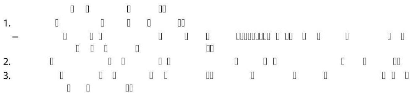
![USPO 0" 4 USPO P□□□□□ □□□□□□□□□□□ □ USPO P□□□□□ □□□□□□□□□□□ □ USPO P□□□□□ □□□□□□□□□□□ □ 1. □ □ □ □ □ □ □ □ □ 2. □ □ -1SP BS□1S V □□ □ □ □ □ □ □ □ -1SP BS□ BTT □□ □ □ □ □ □ □ 3. □ □ □ □ -1SP BS□1S V □□ □ □ □ □ □ □ □ -1SP BS□ BTT □□ □ □ □ □ □ □ 4. □ □ USPO □ □ [→] )](/content/2026/04/650336/images/bf7eced21f06fe01ea596baf1f7be5c0fccc44fb905763615c4eca6ed6a694da.jpg)

BTN0017
BioTec ScreenMatic
| ● | |||||||||||
| □ | |||||||||||
| ● | |||||||||||
| □□□□□□□□□□□□□□□□□□□□□□□□□□□□□□□□□□□□□□□□□□□□□□□□□□□□□□□□□□□□□□□□□□□□□□□□□□□□□□□□□□□□□□□□□□□□□□□□□□□□○□□□□□□□□□□□□□□□□□□□□□□□□□□□□□□□□□□□□□□□□□□□□□□□□□□□□□□□□□□□□□□□□□□□□□□□□□□□□□□□□□□□□□□□□□□□□□□□□□□□ □□□□□□□□□□□□□□□□□□□□□□□□□□□□□□□□□□□□□□□□□□□□□□□□□□□□□□□□□□□□□□□□□□□□□□□□□□□□□□□□□□□□□□□□□□□□□□□□□□□□口□□□□□□□□□□□□□□□□□□□□□□□□□□□□□□□□□□□□□□□□□□□□□□□□□□□□□□□□□□□□□□□□□□□□□□□□□□□□□□□□□□□□□□□□□□□□□□□□□□□ | |||||||||||
| 1. | |||||||||||
| 2. | |||||||||||
| 3. | |||||||||||
BTN0005
BTN0016
RU
RU
| [℃] | [ | [ | [ | [ | [ | [ | [ | [ | |||
| < | < | < < | < < | < | |||||||
| [%] | [%] | [%] | |||||||||
| 4 | 12 | 72 | 14 | 12 | 12 | 50 | 24 | 12 | 67 | ||
| 5-9 | 12 | 36 | 25 | 24 | 12 | 67 | 48 | 12 | 80 | ||
| 10 - 14 | 12 | 12 | 50 | 36 | 12 | 75 | 96 | 12 | 89 | ||
| 15 - 19 | 12 | 0 | 100 | 12 | 0 | 100 | 12 | 0 | 100 | ||
| ≥ 20 | 12 | 12 | 50 | 36 | 12 | 75 | 12 | 0 | 100 | ||
RU
BTN0006
BTN0010
RU

BTN0012
RU

BTN0002

BTN0011
flowchart
graph TD
    A["Start"] --> B{Condition}
    B -->|Yes| C["Process Step 1"]
    B -->|No| D["Process Step 2"]
    C --> E{Condition}
    D --> F{Condition}
    E --> G["Output"]
    F --> H["Output"]
    G --> I["End"]

    subgraph Process Steps
        J["Start"] --> K{Condition}
        K -->|Yes| L["Process Step 1"]
        K -->|No| M["Process Step 2"]
        L --> N{Condition}
        M --> O["Process Step 3"]
        N --> P["Output"]
        O --> Q["End"]

    end

    subgraph Final Output
        R["End"]
    end

    style A fill:#f9f,stroke:#333
    style B fill:#ccf,stroke:#333
    style C fill:#cfc,stroke:#333
    style D fill:#fcc,stroke:#333
    style E fill:#ffc,stroke:#333
    style F fill:#fcc,stroke:#333
    style G fill:#cff,stroke:#333
    style H fill:#ffc,stroke:#333
    style I fill:#cfc,stroke:#333
    style J fill:#fcc,stroke:#333
    style K fill:#cfc,stroke:#333
    style L fill:#fcc,stroke:#333
    style M fill:#cfc,stroke:#333
    style N fill:#cfc,stroke:#333
    style O fill:#fcc,stroke:#333
    style P fill:#cfc,stroke:#333
    style Q fill:#fcc,stroke:#333
    style R fill:#cfc,stroke:#333
    style S fill:#fcc,stroke:#333
RU
| Bitron Eco | 120 W | 180 W | 240 W | ||
| 220-240 | 220-240 | 220-240 | |||
| □□□□□□ | □□□□□□ | □□□□□□ | |||
| 120 | 180 | 240 | |||
| 120 | 180 | 240 | |||
| 60W TC-L (UV-C) | 60 W TC-L (UV-C) | 60 W TC-L (UV-C) | |||
| 12000 | 12000 | 12000 | |||
| +4...+35 | +4...+35 | +4...+35 | |||
| ±1±1±1 | |||||
| 5 | 5 | 5 | |||
| 1 | 1 | 1 | |||
| 38/50 | 38/50 | 38/50 | |||
| 11⁄2/2 | 11⁄2/2 | 11⁄2/2 | |||
| 2 | 2 | 2 | |||
| 38/50 | 38/50 | 38/50 | |||
| 11⁄2/2 | 11⁄2/2 | 11⁄2/2 | |||
| 50000 | 50000 | 50000 | |||
| 1 | 1 | 1 | |||
| 725×227×248 | 725×227×248 | 725×227×248 | |||
| 7,9 | 7,9 | 8,1 | |||
| 15,8 | 15,8 | 16,0 | |||
RU
原始说明书。
警告
BTN0003
Pos. 数量 Bitron Eco 120 W, 180 W, 240 W
CN
连接输入端
请使用至少适用于1巴的软管。
推荐使用软管接头的组合方式:
输入口 输出口 1 输出口 2
所需配件
(输入口处对侧)
| 50 mm (2 in) 50 mm (2 in) 已锁定 - | |||
| 38 mm (1 12 in) 38 mm (1 12 in) 已锁定 - | |||
| 38 mm (1 12 in) | 38 mm (1 12 in) | 38 mm (1 12 in) | 用于输出口2的38mm(1 12 in)软管接头,带有38 mm (1 12 in) 的锁紧螺母 |
| 50 mm (2 in) | 38 mm (1 12 in) | 38 mm (1 12 in) | |
步骤如下:
- 将入口喷嘴推入入口处中。
BTN0009
更换损坏的UVC灯泡
BTN0011
存放/过冬
- Bitron Eco
- Eingang anschließen
- Lagern/Überwintern
- Safety information
- Electrical connection
- Safe operation
- Intended use
- Product Description
- Overview
- Control system overview
- Properties
- Installation and connection
- Operation with pool water or salt water
- Distances to be adhered to
- Solo operation
- Connecting the inlet
- Connecting the outlet
- Connect the unit to the flow-through filter
- ProfiClear Premium / ProfiClear Classic
- How to proceed:
- BioTec ScreenMatic
- With bypass
- Without bypass
- Commissioning/start-up
- NOTE
- Order of starting up steps
- Operation
- Switching ON/OFF
- Selecting the operating mode
- Resetting the operating hour counter
- Maintenance and cleaning
- Regular tasks
- Dismantling the unit head
- CAUTION
- Fitting the unit head
- Exchange the UVC lamp
- Replacing a defective UVC lamp
- Cleaning/replacing the quartz glass
- Storage/winter protection
- Malfunction remedy
- Malfunctions
- System messages
- Technical data
- Wear parts
- Disposal
- AVERTISSEMENT
- Brancher l'entrée
- Sluit de ingang aan
- Defecte UVC-lamp vervangen
- Opslag/overwinteren
- Pos. Nú-
- Bitron Eco 120 W, 180 W, 240 W
- mero
- Ligar com a entrada
- Collegare entrata
- Tilslut indgang
- Opbevaring/overvintring
- Koble til inngang
- Skifte defekt UVC-lampe
- Ansluta ingången
- Byta ut en söndrig UVC-lampa
- Laitepään asennus
- Toimit näin:
- Tárolás/Telelés
- NÓ 『』『μ』『ü Àç』『μ』
- NäμßÓÀ Íæi β
- j ì□□ □ ì□□ j □□ □äμ □
- Ulo ení/zazimování
- B æiâ Ó ì ßÓâ ÿ
- Poruchy
- Systémová hlá ení
- Pripojenie vstupu
- Obsluha
- Zapnutie / Vypnutie
- j ì Ó Ïμ ÏÓ ì Ïßâ Ð Ó Ï Ó Ï
- μæi ìμ ïò â
- UPOZORNENIE
- Pregled krmilnik
- Lastnosti
- Postavitev in priklop
- Priklop vhoda
- Redna opravila
- Snemanje glave naprave
- PREVIDNO
- NASVET
- U □ μ □ IÀ Nâ μ Ó IÀ
- Nâ Ïsâ Æ Ó Ó æ æi Þ
- Nâμ À μ ÊÀ □ □
- Stavljanje u pogon
- NAPOMENA
- ì Ó μâ βμμ j ì
- Mesaje-sistem
- Date tehnice
- 警告
- 连接输入端
- 更换损坏的UVC灯泡
- 存放/过冬
Brand : OASE
Model : Bitron Eco 120W
Category : Water filter