
CU-E15NKR - Air conditioner PANASONIC - Free user manual and instructions
Find the device manual for free CU-E15NKR PANASONIC in PDF.
| Product type | Split system air conditioner, outdoor unit |
| Brand | Panasonic |
| Model | CU-E15NKR |
| Cooling capacity | 5.0 kW (17,000 BTU/h) |
| Heating capacity | 6.0 kW (20,500 BTU/h) |
| Power supply | 230 V ~ 50 Hz, single phase |
| Power consumption (cooling) | 1.5 kW |
| Power consumption (heating) | 1.8 kW |
| Refrigerant | R32 |
| Dimensions (outdoor unit) | 780 x 650 x 290 mm (W x H x D) |
| Weight (outdoor unit) | 34 kg |
| Noise level (outdoor) | 48 dB(A) |
| Main functions | Cooling, heating, dehumidification, ventilation, silent mode, 24h timer |
| Energy class (cooling) | A++ |
| Energy class (heating) | A+ |
| Maintenance and cleaning | Clean the air filters every 2 weeks with a vacuum cleaner or warm water. Check the condenser fins once a year. |
| Safety | Automatic shutdown device in case of overheating, anti-freeze protection, refrigerant leak detection |
| Spare parts and repairability | Repairability index: 8.2/10. Spare parts available through Panasonic authorized service. |
| General information | Compatible with infrared remote control, inverter conduction, manufacturer warranty 2 years. |
Frequently Asked Questions - CU-E15NKR PANASONIC
User questions about CU-E15NKR PANASONIC
0 question about this device. Answer the ones you know or ask your own.
Ask a new question about this device
Download the instructions for your Air conditioner in PDF format for free! Find your manual CU-E15NKR - PANASONIC and take your electronic device back in hand. On this page are published all the documents necessary for the use of your device. CU-E15NKR by PANASONIC.
USER MANUAL CU-E15NKR PANASONIC
Your Home In The Cloud

natural_image
Simple icon of a house with a cloud, no text or symbols presentPA-AC-WIFI-1A
INSTALLATION GUIDE
Installation process should only be performed by an authorized installer. Please follow all Safety Instructions provided by the Panasonic manuals.
1. Product description
The IntesisHome device is an external module capable of connecting Panasonic Air Conditioning units into your Wi-Fi network in order to provide global connectivity and remote control applications through a friendly user interface.
Packaging content:
- IntesisHome Device
- External Antenna
- Supplied cable
- Temperature sensor
- Quick start guide
- Installation guide
- Warranty Doc
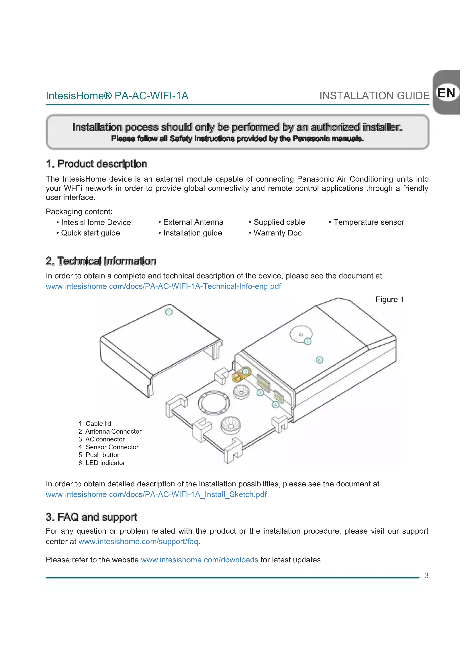
2. Technical information
In order to obtain a complete and technical description of the device, please see the document at www.intesishome.com/docs/PA-AC-WIFI-1A-Technical-Info-eng.pdf
In order to obtain detailed description of the installation possibilities, please see the document at www.intesishome.com/docs/PA-AC-WIFI-1A_Install_Sketch.pdf
3. FAQ and support
For any question or problem related with the product or the installation procedure, please visit our support center at www.intesishome.com/support/faq.
Please refer to the website www.intesishome.com/downloads for latest updates.
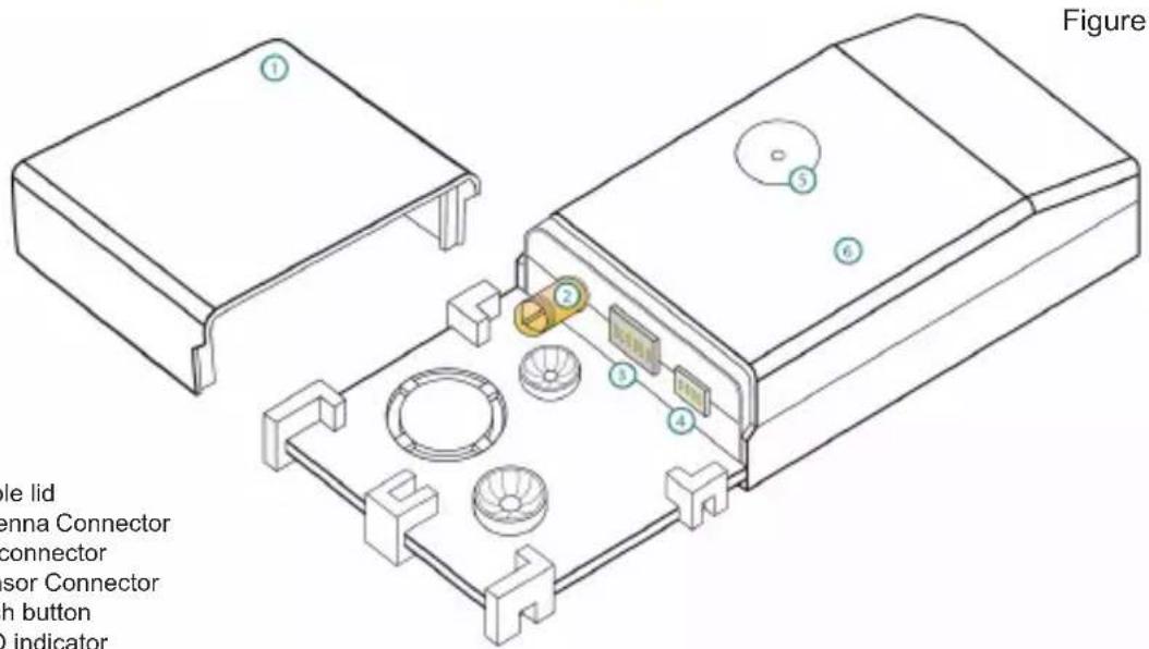
4. Installation overview
5. Device connections
-
Unplug the Air conditioner (AC) unit from the power supply line
-
Access to the main Printed Circuit Board.*
-
Locate the socket connector marked as CN-CNT*
-
Select a location for the IntesisHome device. See section 6 for more information.
-
Connect the A-end (the long one) of the supplied cable to the Air Conditioner CN-CNT connector and the B-end (the short one) to the device AC connector.
-
Connect the external antenna into the antenna connector. Make sure you screw the antenna connector in a clockwise direction until it stops.
-
(If needed) Install the Temperature Sensor. See section 8 for more information.
-
Place the antenna outside the AC, preferably in a vertical position and pointing directly to the Wi-Fi Router or Access Point (AP). See section 7 for more information.
-
Close the Air Conditioner unit.
-
Plug the AC to the power supply line. If connection with the Air Conditioner has been successful, IntesisHome device LED will start blinking Green and then will change to steady Green.
* See Panasonic installation or service manual for detailed information.
6. Device location
IntesisHome device can be both installed inside or outside the AC units.
In order to obtain detailed description of the installation possibilities, please see the document at www.intesishome.com/docs/PA-AC-WIFI-1A_Install_Sketch.pdf
Figure 3
natural_image
Technical line drawing of a device housing with labeled components (no text or symbols present)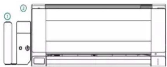
natural_image
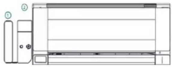
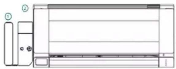
Technical line drawing of a front view of an air conditioner unit with labeled components (no text or symbols beyond labels)Inside the AC unit Outside the AC unit
1. External antenna
2. IntesisHome device
Device Installed inside the AC unit or hidden
It allows a neater installation as the user cannot see the device during normal operation. The following points need to be taken into account if the device is installed inside the AC.
- The indication LED and the button are not going to be accessible by the user.
o The LED is an indicator of the status of the device both during connection and normal behavior.
o The button is used to reconfigure the device if the Access Point (AP) configuration changes. If this happens the user will need to access the inside of the Air Conditioner.
- If there is not enough space for installation inside the AC unit the following actions can be performed:
o If it is due to water pipes, change the side of the AC where they are connected to get more space inside the AC unit.
o Otherwise the support surface can be removed (Figure 1)
Device Installed outside the AC unit
The following points need to be taken into account if the device is installed outside the AC.
- The device can be fixed both using screws of double side tape.
- The cable lid has several options in order to direct the cables to the desired direction.
7. Antenna location
Locating the external antenna in a proper location and position will improve communication between the IntesisHome device and your Wi-Fi Router or Access Point (AP).
Remember to correctly screw the antenna connector in a clockwise direction until it stops.
Important: Avoid placing the antenna next to metal surfaces.
Important: When possible, try to check Wi-Fi coverage in the installation location. Good Wi-Fi level is strongly recommended.
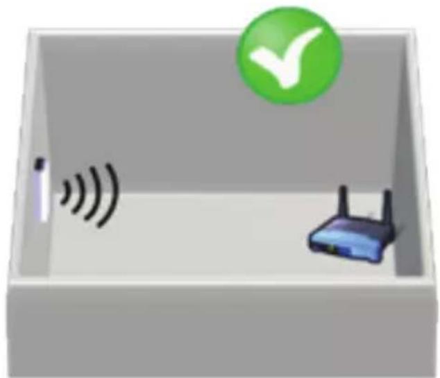
Fix the external antenna preferably as close as possible from the Wi-Fi signal source (Access Point or Router). Please, make sure that you place the antenna in a vertical position and pointing directly to your Wi-Fi Router or Access Point (AP).
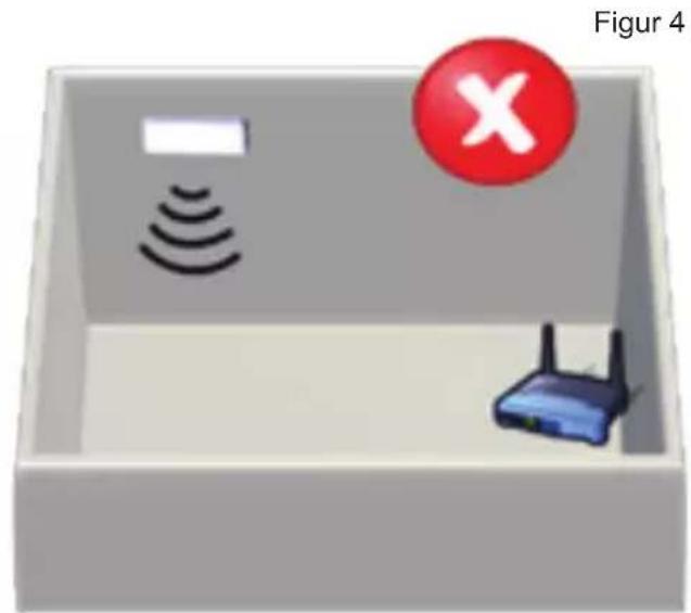
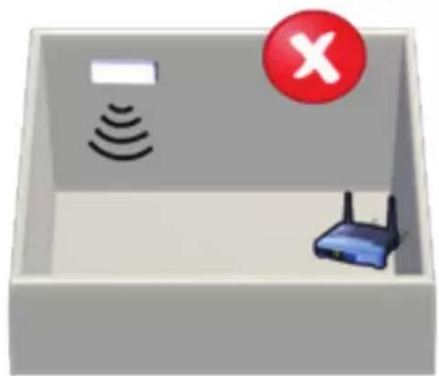
Figure 4
natural_image
3D illustration of a device with wireless signal waves, a router, and a green checkmark (no text or symbols)Antenna in vertical position and pointing to the Wi-Fi Access Point or Router.
natural_image
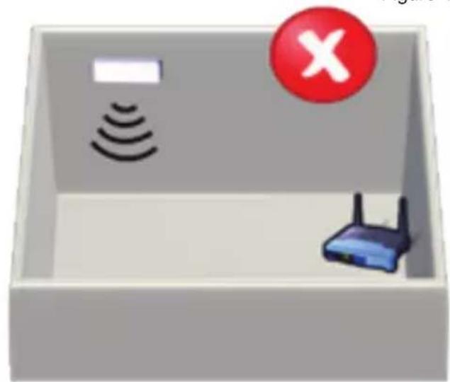
3D illustration of a device with wireless signals and a router inside a rectangular box, marked with a red 'X' symbol (no text or labels)Antenna in horizontal position and melt pointing to the Wi-Fi Access Point or Router.
If you have coverage problems after installation, please visit the connectivity support section in our site at www.intesishome.com/support/faq
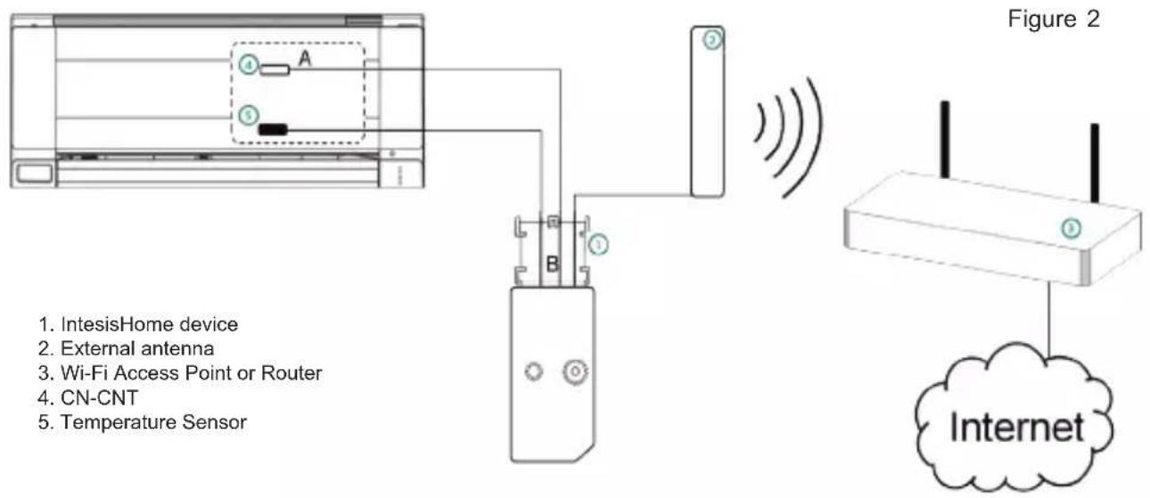
8. Temperature Sensor location
The supplied temperature sensor only needs to be installed in MKE and NKE units. Newer models do not require an external temperature sensor.
Connect the temperature sensor to the device Temperature Sensor connector (Figure 1) and fix the other end next to the Air Conditioner intake air sensor.
See www.intesishome.com/docs/PA-AC-WIFI-1A_Install_Sketch.pdf for more information
natural_image
Technical line drawing of a front panel with labeled components (no text or symbols)natural_image
3D illustration of a device with wireless signal waves, a router, and a green checkmark (no text or symbols)natural_image
3D illustration of a device with wireless signals, a router, and a red 'X' symbol (no text or labels)natural_image
Technical line drawing of a device chassis with labeled parts (no text or symbols present)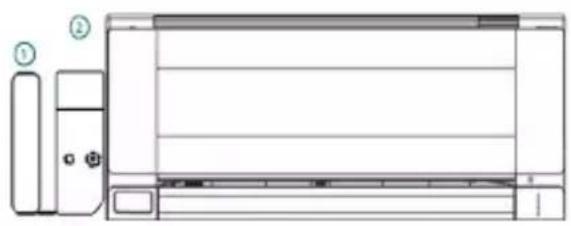
natural_image
Technical line drawing of a front-mounted air conditioner unit with labeled components (no text or symbols beyond labels)natural_image
3D illustration of a device with wireless signal waves, a router, and a green checkmark (no text or symbols)natural_image
3D illustration of a device with wireless signals and a router inside a rectangular box, marked with a red 'X' symbol (no text or labels)natural_image
Technical line drawing of a mechanical device with labeled parts (no text or symbols present)Figura 3
natural_image
Technical line drawing of a front view of a rectangular electronic device with labeled ports (no text or symbols present)natural_image
3D illustration of a device with wireless signal waves, a router, and a green checkmark (no text or symbols)natural_image
3D illustration of a box containing wireless signals and a router, with a red 'X' symbol in the top-right corner (no text or symbols on main objects)natural_image
Technical line drawing of a front panel with labeled components (no text or symbols present)Figura 3
natural_image
3D illustration of a device with wireless signal waves, a router, and a green checkmark (no text or symbols)natural_image
3D illustration of a device inside a box with wireless signals and a router, no text or symbols presentnatural_image
Technical line drawing of a mechanical device with labeled parts (no text or symbols present)natural_image
Technical line drawing of a front-mounted air conditioner unit with labeled components (no text or symbols present)- Ekstern antenne
- IntesisHome-enhet
natural_image
3D illustration of a device with wireless signal waves, a router, and a green checkmark (no text or symbols)Antennen i vertikall posisjon og påker met WM-FI-61-gangspunktat eller rutaren
natural_image
3D illustration of a device inside a box with wireless signals and a router, marked with a red circle containing an 'X' symbol (no text or labels on main elements)Antennen I horttismtall posikijenoggpelektliskenetot WI-FI-tligangspunktet eller ruteren
natural_image
Technical line drawing of a front-mounted air conditioner unit with labeled components (no text or symbols present)Inuti luftkonditioneringsenheten Utanför luftkonditioneringsenheten
- Extern Antenn
- IntesisHome-enhet
natural_image
3D illustration of a device with wireless signal waves, a router, and a green checkmark (no text or symbols)natural_image
3D diagram of a device with wireless signals, a router, and a red circle containing an 'X' symbol (no text or labels)Antemnem il horiksonbalt lige, som ihle geltar mett WI-FI-ätkomstpunktdam eller -routern
natural_image
Technical line drawing of a mechanical device with labeled parts (no text or symbols present)natural_image
Technical line drawing of a front view of an air conditioner unit with labeled components (no text or symbols beyond labels)- Udvendig antenne
- IntesisHome apparat
Apparat monteret inde i AC-enheden eller skjult
natural_image
3D illustration of a device with wireless signal waves, a router, and a green checkmark (no text or symbols)Antennen i lodret position og vender mod Wi-Fi Access Point eller router
natural_image
3D illustration of a device with wireless signals and a router inside a gray box, marked with a red 'X' symbol (no text or labels)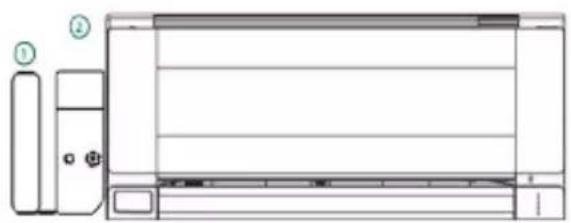
natural_image
Technical line drawing of a front panel with labeled components (no text or symbols present)natural_image
3D illustration of a device with wireless signal waves, a router, and a green checkmark (no text or symbols)natural_image
3D illustration of a device with wireless signals and a router inside a rectangular box, marked with a red 'X' symbol (no text or labels)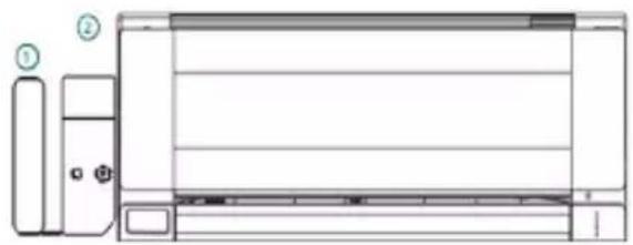
natural_image
Diagram of a front view of an air conditioner unit with labeled components (no text or symbols present)natural_image
3D illustration of a device with wireless signal waves, a router, and a green checkmark (no text or symbols)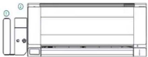
natural_image
Technical line drawing of a front panel with labeled components (no text or symbols present)natural_image
3D illustration of a device with wireless signal waves, a router, and a green checkmark (no text or symbols)natural_image
3D illustration of a device with wireless signals and a router inside a rectangular box, marked with a red 'X' symbol (no text or labels)www.intesishome.com/docs/PA-AC-WIFI-1A_Install_Sketch.
Intesis Software, S.L. - Milà i Fontanals 1bis - 08700 IGUALADA (Barcelona) - SPAIN
info@intesishome.com - www.intesishome.com
- Installation process should only be performed by an authorized installer. Please follow all Safety Instructions provided by the Panasonic manuals.
- Product description
- Technical information
- FAQ and support
- Installation overview
- Device connections
- Device location
- Device Installed inside the AC unit or hidden
- Device Installed outside the AC unit
- Antenna location
- Temperature Sensor location
- Apparat monteret inde i AC-enheden eller skjult
Brand : PANASONIC
Model : CU-E15NKR
Category : Air conditioner