
J4125M - Motherboard ASROCK - Free user manual and instructions
Find the device manual for free J4125M ASROCK in PDF.

| Product Type | Motherboard |
| Brand | ASROCK |
| Model | J4125M |
| Form Factor | Micro ATX |
| Integrated CPU | Intel Quad-Core J4125 (up to 2.7 GHz) |
| RAM Memory | 2 x DDR4, max 8 GB, 2400/2133 MHz non-ECC |
| Integrated Graphics | Intel UHD 600 (12 EUs, up to 750 MHz) |
| Video Outputs | D-Sub, DVI-D, HDMI 2.0 (4K@60Hz) |
| Audio | Realtek ALC887, 7.1 channel HD |
| Network | Gigabit Ethernet Realtek RTL8111E |
| Storage | 2 x SATA3 6 Gb/s |
| Expansion Slots | 1 x PCIe 2.0 x16 (x1), 2 x PCIe 2.0 x1, 1 x M.2 Key E (Wi-Fi/BT) |
| Rear USB Connectors | 2 x USB 3.2 Gen1, 2 x USB 2.0 |
| PS/2 Ports | 1 mouse, 1 keyboard |
| BIOS | UEFI AMI with GUI |
| Power Supply | ATX 24-pin |
| Supported Operating System | Windows 10 64-bit |
| Certifications | FCC, CE, ErP/EuP Ready |
Frequently Asked Questions - J4125M ASROCK
User questions about J4125M ASROCK
0 question about this device. Answer the ones you know or ask your own.
Ask a new question about this device
Download the instructions for your Motherboard in PDF format for free! Find your manual J4125M - ASROCK and take your electronic device back in hand. On this page are published all the documents necessary for the use of your device. J4125M by ASROCK.
USER MANUAL J4125M ASROCK
Published December 2019
Copyright ©2019 ASRock INC. All rights reserved.
Copyright Notice:
No part of this documentation may be reproduced, transcribed, transmitted, or translated in any language, in any form or by any means, except duplication of documentation by the purchaser for backup purpose, without written consent of ASRock Inc.
Products and corporate names appearing in this documentation may or may not be registered trademarks or copyrights of their respective companies, and are used only for identification or explanation and to the owners' benefit, without intent to infringe.
Disclaimer:
Specifications and information contained in this documentation are furnished for informational use only and subject to change without notice, and should not be constructed as a commitment by ASRock. ASRock assumes no responsibility for any errors or omissions that may appear in this documentation.
With respect to the contents of this documentation, ASRock does not provide warranty of any kind, either expressed or implied, including but not limited to the implied warranties or conditions of merchantability or fitness for a particular purpose.
In no event shall ASRock, its directors, officers, employees, or agents be liable for any indirect, special, incidental, or consequential damages (including damages for loss of profits, loss of business, loss of data, interruption of business and the like), even if ASRock has been advised of the possibility of such damages arising from any defect or error in the documentation or product.

This device complies with Part 15 of the FCC Rules. Operation is subject to the following two conditions:
(1) this device may not cause harmful interference, and
(2) this device must accept any interference received, including interference that may cause undesired operation.
CALIFORNIA, USA ONLY
The Lithium battery adopted on this motherboard contains Perchlorate, a toxic substance controlled in Perchlorate Best Management Practices (BMP) regulations passed by the California Legislature. When you discard the Lithium battery in California, USA, please follow the related regulations in advance.
"Perchlorate Material-special handling may apply, see www.dtsc.ca.gov/hazardouswaste/perchlorate"
ASRock Website: http://www.asrock.com
AUSTRALIA ONLY
Our goods come with guarantees that cannot be excluded under the Australian Consumer Law. You are entitled to a replacement or refund for a major failure and compensation for any other reasonably foreseeable loss or damage caused by our goods. You are also entitled to have the goods repaired or replaced if the goods fail to be of acceptable quality and the failure does not amount to a major failure. If you require assistance please call ASRock Tel: +886-2-28965588 ext.123 (Standard International call charges apply)
The terms HDMI^※ and HDMI High-Definition Multimedia Interface, and the HDMI logo are trademarks or registered trademarks of HDMI Licensing LLC in the United States and other countries.

Motherboard Layout
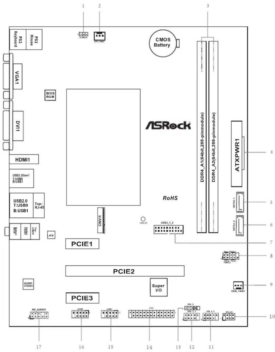
No.Description
1 Clear CMOS Jumper (CLRMOS1)
2 CPU Fan Connector (CPU_FAN1)
3 2 x 288-pin DDR4 DIMM Slots (DDR4_A1, DDR4_A2)
4 ATX Power Connector (ATXPWR1)
5 SATA3 Connector (SATA3_1)
6 SATA3 Connector (SATA3_2)
7 USB 3.2 Gen1 Header (USB3_1_2)
8 System Panel Header (PANEL1)
9 Chassis Fan Connector (CHA_FAN1)
10 Chassis Intrusion and Speaker Header (SPK_C11)
11 USB 2.0 Header (USB_4_5)
12 USB 2.0 Header (USB_2_3)
13 USB 2.0 Header (USB_6)
14 Print Port Header (LPT1)
15 COM Port Header (COM1)
16 COM Port Header (COM2)
17 Front Panel Audio Header (HD_AUDIO1)
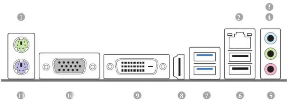
I/O Panel
No. Description No. Description
1 PS/2 Mouse Port
2 LAN RJ-45 Port
3 Line In (Light Blue)
4 Front Speaker (Lime)*
5 Microphone (Pink)**
6 USB2.0Ports(USB01)
7 USB 3.2 Gen1 Ports (USB3_01)
8 HDMI Port
9 DVI-D Port
10 D-Sub Port
11 PS/2 Keyboard Port
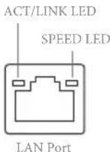
Activity / Link LED Speed LED
Status Description Status Description
| Off No Link Off | 10Mbps connection |
| Blinking Data Activity | Orange 100Mbps connection |
| On Link Green | Gbps connection |
To configure 7.1 CH HD Audio, it is required to use an HD front panel audio module and enable the multichannel audio feature through the audio driver.
Please set Speaker Configuration to "7.1 Speaker" in the Realtek HD Audio Manager.

Function of the Audio Ports in 7.1-channel Configuration:
| Port Function | |
| Light Blue (Rear panel) Rear Speaker Out | |
| Lime (Rear panel) Front Speaker Out | |
| Pink (Rear panel) Central /Subwoofer Speaker Out | |
| Lime (Front panel) Side Speaker Out | |
Chapter 1 Introduction
Thank you for purchasing ASRock J4125M / J4025M motherboard, a reliable motherboard produced under ASRock's consistently stringent quality control. It delivers excellent performance with robust design conforming to ASRock's commitment to quality and endurance.

Because the motherboard specifications and the BIOS software might be updated, the content of this documentation will be subject to change without notice. In case any modifications of this documentation occur, the updated version will be available on ASRock's website without further notice. If you require technical support related to this motherboard, please visit our website for specific information about the model you are using. You may find the latest VGA cards and CPU support list on ASRock's website as well. ASRock website http://www.asrock.com.
1.1 Package Contents
ASRock J4125M / J4025M Motherboard (Micro ATX Form Factor)
ASRock J4125M / J4025M Quick Installation Guide
ASRock J4125M / J4025M Support CD
- 2 × Serial ATA (SATA) Data Cables (Optional)
- 1 x Screw for M.2 Socket (Optional)
- 1 x I/O Panel Shield
1.2 Specifications
Platform
- Micro ATX Form Factor
Solid Capacitor design
CPU
- Intel Quad-Core Processor J4125 (up to 2.7 GHz) (for J4125M)
- Intel® Dual-Core Processor J4025 (up to 2.9 GHz) (for J4025M)
Memory
Dual Channel DDR4 Memory Technology
- 2x DDR4 DIMM Slots
- 2GB DRAM per module is not supported.
Supports DDR4 2400/2133 non-ECC, un-buffered memory
Max. capacity of system memory: 8GB
- Intel Extreme Memory Profile (XMP) is not supported
Expansion
- 1 x PCI Express 2.0 x16 Slot (PCIE2: x1 mode)
Slot
- 2 x PCI Express 2.0 x1 Slots
-
1 x M.2 Socket (Key E), supports type 2230 Intel® CNVi (Integrated WiFi/BT)
-
M.2 PCI Express module is not supported.
Graphics
- Integrated Intel® UHD Graphics 600: 12 EUs inside (Up to 750MHz) (for J4125M)
- Integrated Intel® UHD Graphics 600: 12 EUs inside (Up to 700MHz) (for J4025M)
DX12, OpenGL 4.4, OGL ES 3.1, OpenCL 1.2 - HW Acceleration Decode: HEVC (H.265) 8 bit, HEVC (H.265)10 bit, H.264 @ Lvl5.2 (AVC), JPEG/MJPEG, VP8, VP9 8bit, VP9 10 bit
- HW Acceleration Encode: HEVC (H.265) 8 bit, HEVC (H.265)10 bit, H.264 @ Lvl5.2 (AVC), JPEG/MJPEG, VP8, VP9 8bit
Three graphics output options: D-Sub, DVI-D and HDMI
Supports Triple Monitor
Supports HDMI 2.0 with max. resolution up to 4K× 2K (4096x2160) @ 60Hz
Supports DVI-D with max. resolution up to 1920x1200 @ 60Hz
| Supports D-Sub with max. resolution up to 2048x1536 @ 60Hz Supports Auto Lip Sync, xvYCC and HBR (High Bit Rate Audio) with HDMI 2.0 Port (Compliant HDMI monitor is required) Supports HDCP 2.2 with DVI-D and HDMI 2.0 Ports Supports Full HD 1080p Blu-ray (BD) playback with DVI-D and HDMI 2.0 Ports | |
| Audio | 7.1 CH HD Audio (Realtek ALC887 Audio Codec) * To configure 7.1 CH HD Audio, it is required to use an HD front panel audio module and enable the multi-channel audio feature through the audio driver. Supports Surge Protection ELNA Audio Caps |
| LAN | PCIE x1 Gigabit LAN 10/100/1000 Mb/s Realtek RTL8111E Supports Wake-On-LAN Supports Lightning/ESD Protection Supports Energy Efficient Ethernet 802.3az Supports PXE |
| Rear Panel I/O | 1 x PS/2 Mouse Port 1 x PS/2 Keyboard Port 1 x D-Sub Port 1 x DVI-D Port 1 x HDMI Port 2 x USB 2.0 Ports (Supports ESD Protection) 2 x USB 3.2 Gen1 Ports (Supports ESD Protection) 1 x RJ-45 LAN Port with LED (ACT/LINK LED and SPEED LED) HD Audio Jacks: Line in / Front Speaker / Microphone |
| Storage | 2 x SATA3 6.0 Gb/s Connectors, support NCQ, AHCI and Hot Plug |
Connector
1xPrintPortHeader
- 2x COM Port Headers
1x Chassis Intrusion and Speaker Header
- 1 x CPU Fan Connector (3-pin)
- 1 x Chassis Fan Connector (3-pin)
- 1 x 24 pin ATX Power Connector
- 1 x Front Panel Audio Connector
- 3 x USB 2.0 Headers (Support 5 USB 2.0 ports) (Supports ESD Protection)
- 1 x USB 3.2 Gen1 Header (Supports 2 USB 3.2 Gen1 ports) (Supports ESD Protection)
BIOS
Feature
AMI UEFI Legal BIOS with GUI support
Supports Plug and Play
ACPI 5.0 compliant wake up events
Supports jumperfree
SMBIOS 3.0 support
Hardware
Monitor
CPU/Chassis temperature sensing
CPU/Chassis Fan Tachometer
CPU/Chassis Quiet Fan (Auto adjust chassis fan speed by CPU temperature)
CPU/Chassis Fan multi-speed control
CASE OPEN detection
Voltage monitoring: +12V, + 5V, + 3.3V CPU Vcore
0S
- Microsoft® Windows® 10 64-bit
- Supports UEFI mode only
Certifica
FCC,CE
ErP/EuP ready (ErP/EuP ready power supply is required)
- For detailed product information, please visit our website: http://www.asrock.com
Chapter 2 Installation
This is a Micro ATX form factor motherboard. Before you install the motherboard, study the configuration of your chassis to ensure that the motherboard fits into it.
Pre-installation Precautions
Take note of the following precautions before you install motherboard components or change any motherboard settings.
- Make sure to unplug the power cord before installing or removing the motherboard. Failure to do so may cause physical injuries to you and damages to motherboard components.
- In order to avoid damage from static electricity to the motherboard's components, NEVER place your motherboard directly on a carpet. Also remember to use a grounded wrist strap or touch a safety grounded object before you handle the components.
- Hold components by the edges and do not touch the ICs.
- Whenever you uninstall any components, place them on a grounded anti-static pad or in the bag that comes with the components.
- When placing screws to secure the motherboard to the chassis, please do not overtighten the screws! Doing so may damage the motherboard.
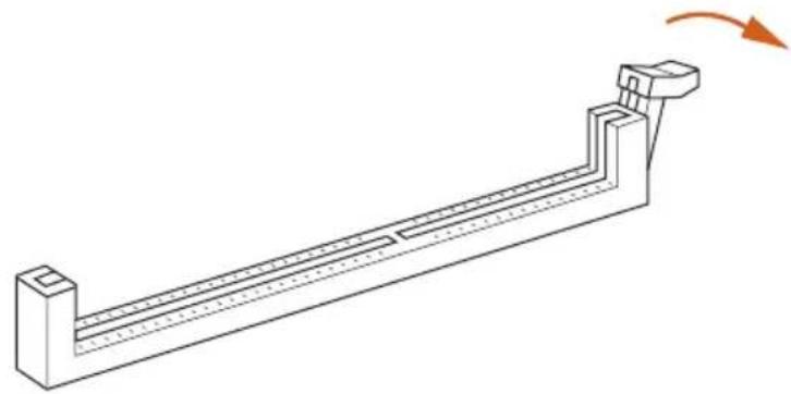
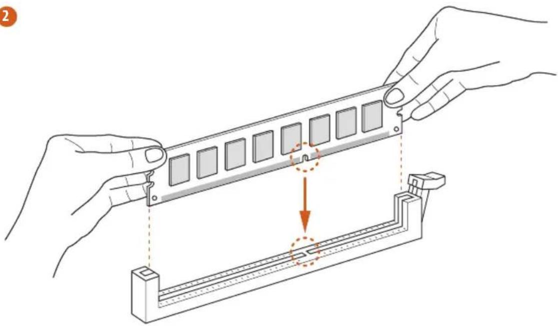
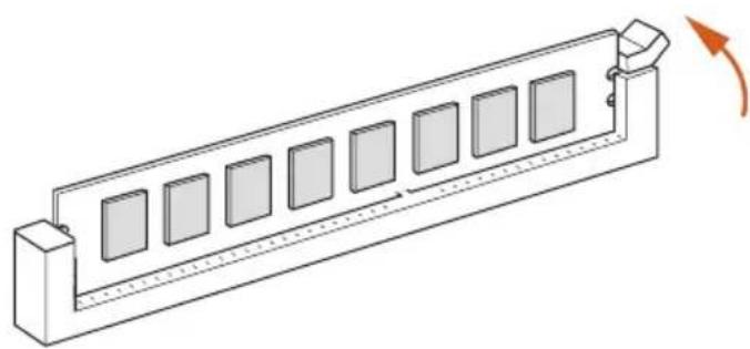
2.1 Installing Memory Modules (DIMM)
This motherboard provides two 288-pin DDR4 (Double Data Rate 4) DIMM slots, and supports Dual Channel Memory Technology.

- It is not allowed to install a DDR, DDR2 or DDR3 memory module into a DDR4 slot; otherwise, this motherboard and DIMM may be damaged.
- The DIMM only fits in one correct orientation. It will cause permanent damage to the motherboard and the DIMM if you force the DIMM into the slot at incorrect orientation.
Supported DDR4 Non ECC DIMM
Raw Card
A (1Rx8)
B (2Rx8)
C (1Rx16)
Dual Channel Memory Configuration
DDR4_A1
Populated
DDR4_A2
Populated
1
2
3
2.2 Expansion Slots (PCI Express Slots)
There are 3 PCI Express slots on the motherboard.

Before installing an expansion card, please make sure that the power supply is switched off or the power cord is unplugged. Please read the documentation of the expansion card and make necessary hardware settings for the card before you start the installation.
PCIe slot:
PCIE1 (PCIe 2.0 x1 slot) is used for PCI Express x1 lane width cards.
PCIE2 (PCIe 2.0 x16 slot) is used for PCI Express x1 lane width cards.
PCIE3 (PCIe 2.0 x1 slot) is used for PCI Express x1 lane width cards.
Warning:
To ensure better graphics compatibility, the BIOS is set to "boot from Onboard VGA" as default even the user install a VGA card on PCIe slot.
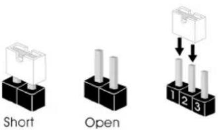
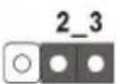
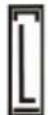
2.3 Jumpers Setup
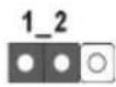
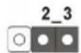
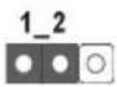
The illustration shows how jumpers are setup. When the jumper cap is placed on the pins, the jumper is "Short". If no jumper cap is placed on the pins, the jumper is "Open". The illustration shows a 3-pin jumper whose pin1 and pin2 are "Short" when a jumper cap is placed on these 2 pins.
Clear CMOS Jumper (CLRMOS1)
(see p.1, No. 1)
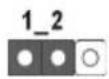
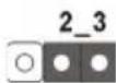
Clear CMOSDefault
CLRMOS1 allows you to clear the data in CMOS. To clear and reset the system parameters to default setup, please turn off the computer and unplug the power cord from the power supply. After waiting for 15 seconds, use a jumper cap to short pin2 and pin3 on CLRMOS1 for 5 seconds. However, please do not clear the CMOS right after you update the BIOS. If you need to clear the CMOS when you just finish updating the BIOS, you must boot up the system first, and then shut it down before you do the clear-CMOS action. Please be noted that the password, date, time, and user default profile will be cleared only if the CMOS battery is removed.

If you clear the CMOS, the case open may be detected. Please adjust the BIOS option "Clear Status" to clear the record of previous chassis intrusion status.
2.4 Onboard Headers and Connectors

Onboard headers and connectors are NOT jumpers. Do NOT place jumper caps over these headers and connectors. Placing jumper caps over the headers and connectors will cause permanent damage to the motherboard.
System Panel Header (9-pin PANEL1) (see p.1, No. 8)
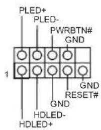
Connect the power switch, reset switch and system status indicator on the chassis to this header according to the pin assignments below. Note the positive and negative pins before connecting the cables.

PWRBTN (Power Switch):
Connect to the power switch on the chassis front panel. You may configure the way to turn off your system using the power switch.
RESET (Reset Switch):
Connect to the reset switch on the chassis front panel. Press the reset switch to restart the computer if the computer freezes and fails to perform a normal restart.
PLED (System Power LED):
Connect to the power status indicator on the chassis front panel. The LED is on when the system is operating. The LED keeps blinking when the system is in S1/S3 sleep state. The LED is off when the system is in S4 sleep state or powered off (S5).
HDLED (Hard Drive Activity LED):
Connect to the hard drive activity LED on the chassis front panel. The LED is on when the hard drive is reading or writing data.
The front panel design may differ by chassis. A front panel module mainly consists of power switch, reset switch, power LED, hard drive activity LED, speaker and etc. When connecting your chassis front panel module to this header, make sure the wire assignments and the pin assignments are matched correctly.
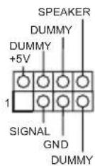
Chassis Intrusion and
Speaker Header
(7-pin SPK_CI1)
(see p.1, No. 10)
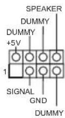
Please connect the chassis intrusion and the chassis speaker to this header.
Serial ATA3 Connectors
(SATA3_1:
see p.1, No. 5)
(SATA3_2:
see p.1, No. 6)
SATA3_1
SATA3_2
These two SATA3
connectors support SATA
data cables for internal
storage devices with up to
6.0 Gb/s data transfer rate.
USB 2.0 Headers
(9-pinUSB_2_3)
(see p.1, No. 12)
(9-pin USB_4_5)
(see p.1, No. 11)
(9-pin USB_6)
(see p.1, No. 13)
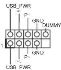
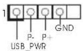
There are three headers on this motherboard.
USB 3.2 Gen1 Header
(19-pin USB3_1_2)
(see p.1, No. 7)
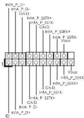
There is one header on
this motherboard. This
USB 3.2 Gen1 header can
support two ports.
Front Panel Audio Header
(9-pin HDAUDIO1)
(see p.1, No. 17)
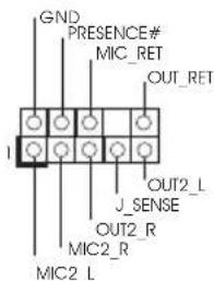
This header is for
connecting audio devices
to the front audio panel.

-
High Definition Audio supports Jack Sensing, but the panel wire on the chassis must support HDA to function correctly. Please follow the instructions in our manual and chassis manual to install your system.
-
If you use an AC'97 audio panel, please install it to the front panel audio header by the steps below:
A. Connect Mic_IN (MIC) to MIC2_L
B. Connect Audio_R (RIN) to OUT2_R and Audio_L (LIN) to OUT2_L.
C. Connect Ground (GND) to Ground (GND).
D. MIC_RET and OUT_RET are for the HD audio panel only. You don't need to connect them for the AC'97 audio panel.
E. To activate the front mic, go to the "FrontMic" Tab in the Realtek Control panel and adjust "Recording Volume".
Chassis Fan Connector
(3-pin CHA_FAN1)
(see p.1, No. 9)
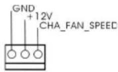
Please connect fan cable to the fan connector and match the black wire to the ground pin.
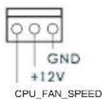
CPU Fan Connector
(3-pinCPU_FAN1)
(see p.1, No. 2)
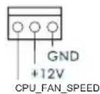
Please connect the CPU fan cable to the connector and match the black wire to the ground pin.
ATX Power Connector
(24-pinATXPWR1)
(see p.1, No. 4)
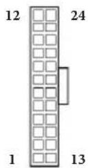
This motherboard provides a 24-pin ATX power connector. To use a 20-pin ATX power supply, please plug it along Pin 1 and Pin 13.
Serial Port Headers
(9-pin COM1)
(see p.1, No. 15)
(9-pin COM2)
(see p.1, No. 16)
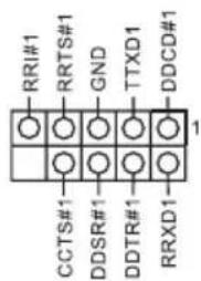
This header supports a serial port module.
Print Port Header
(25-pin LPT1)
(see p.1, No. 14)
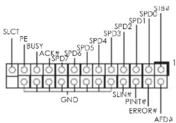
This is an interface for print port cable that allows conveni connection of print devices.
2.5 Intel® CNVi (Integrated WiFi/BT) Installation Guide
The M.2, also known as the Next Generation Form Factor (NGFF), is a small size and versatile card edge connector that aims to replace mPCIe and mSATA. The M.2 Socket (Key E) supports type 2230 Intel CNVi (Integrated WiFi/BT).
Installing Intel® CNVi (Integrated WiFi/BT)
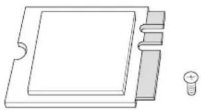
Step 1
Prepare a type 2230 Intel® CNVi (Integrated WiFi/BT) and the screw.
PCB Length: 3cm
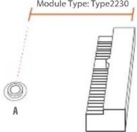
Module Type:Type2230
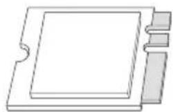
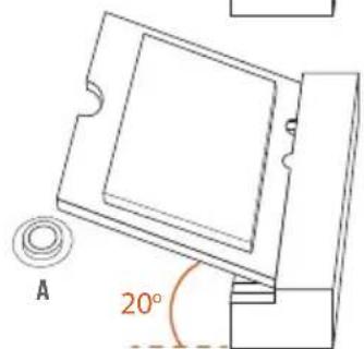
Step 2
Find the nut location to be used.
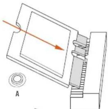
Step 3
Gently insert the type 2230 Intel CNVi (Integrated WiFi/BT) into the M.2 slot. Please be aware that the module only fits in one orientation.
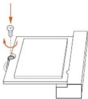
Step 4
Tighten the screw with a screwdriver to secure the module into place.
Please do not overtighten the screw as this might damage the module.
1 Einleitung
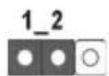
CMOS-loschen-Jumper (CLRMOS1)
(siehe S.1,Nr.1)
CMOS loschenStandard
Cavalier Clear CMOS (CLRMOS1)
(voir p.1, No. 1)
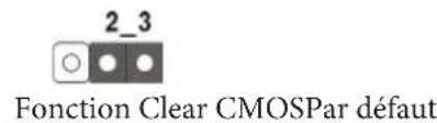
Apagar o Jumper CMOS (CLRMOS1)
(ver p.1, N.° 1)
Apagar CMOSPadrao
Zlacze wentylatora CPU
(3-pinowe CPU_FAN1)
(spreads.1, Nr 2)
HDLED( hdt3rAioB 1EDL):
,
战用,
(7.10)
(1) [10]
新时中日
SIJIALATEA3KITAKT
(SATA3_1:
1.0iJ,5
(SATA3_2:
1.0iJ,6

SATA3_1
SATA3_2
If you need to contact ASRock or want to know more about ASRock, you're welcome to visit ASRock's website at http://www.asrock.com; or you may contact your dealer for further information. For technical questions, please submit a support request form at https://event.asrock.com/tsd.asp
ASRock Incorporation
2F., No.37, Sec. 2, Zhongyang S. Rd., Beitou District,
Taipei City 112, Taiwan (R.O.C.)
ASRock EUROPE B.V.
Bijsterhuizen 11-11
6546 AR Nijmegen
The Netherlands
Phone: +31-24-345-44-33
Fax: +31-24-345-44-38
ASRock America, Inc.
13848 Magnolia Ave, Chino, CA91710
U.S.A.
Phone: +1-909-590-8308
Fax: +1-909-590-1026
DECLARATION OF CONFORMITY
Per FCC Part 2 Section 2.1077(a)

Responsible Party Name: ASRock Incorporation
Address: 13848 Magnolia Ave, Chino, CA91710
Phone/Fax No: +1-909-590-8308/+1-909-590-1026
hereby declares that the product
Product Name : Motherboard
Model Number: J4125M / J4025M
Conforms to the following specifications:
FCC Part 15, Subpart B, Unintentional Radiators
Supplementary Information:
This device complies with part 15 of the FCC Rules. Operation is subject to the following two conditions: (1) This device may not cause harmful interference, and (2) this device must accept any interference received, including interference that may cause undesired operation.
Representative Person's Name: James
Signature :

Date: May 12, 2017
EU Declaration of Conformity
ASRock
For the following equipment:
Motherboard
(Product Name)
J4125M / J4025M / ASRock
(Model Designation / Trade Name)
ASRock Incorporation
(Manufacturer Name)
2F., No.37, Sec. 2, Zhongyang S. Rd., Beitou District, Taipei City 112, Taiwan (R.O.C.)
(Manufacturer Address)
EMC -Directive 2014/30/EU (from April 20th, 2016)
EN 55022:2010/AC:2011 Class B
EN55024:2010/A1:2015
EN55032:2012+AC:2013ClassB
EN61000-3-3:2013
EN61000-3-2:2014
□LVD—Directive 2014/35/EU (from April 20th, 2016)
EN60950-1:2011+A2:2013
EN 60950-1:2006/A12:2011
RoHS - Directive 2011/65/EU
CE marking
(EU conformity marking)
C E
ASRock EUROPE B.V.
(Company Name)
Bijsterhuizen 1111 6546 AR Nijmegen The Netherlands
(Company Address)
Person responsible for making this declaration:

(Name, Surname)
A.V.P
(Position / Title)
January 17, 2020
(Date)
P/N:15G062192000AK V1.0