PV 3 - Measuring equipment BENNING - Free user manual and instructions
Find the device manual for free PV 3 BENNING in PDF.
| Product type | Photovoltaic (PV) tester |
| Brand | BENNING |
| Model | PV 3 |
| Max DC voltage | 1500 V DC |
| Max DC current | 40 A DC |
| Max power | 45 kW |
| Display | Digital LCD screen with polarity indicators and warning |
| Power supply | 3 rechargeable lithium-ion 18650 batteries (3.7 V each, protected version) |
| Recording capacity | Up to 999 measurements |
| PC interface | USB type B with supplied cable |
| PC software | BENNING Solar Datalogger (free download on Benning website) |
| Radio coupling | With BENNING SUN 2 irradiance sensor (optional) |
| Included accessories | 2 measurement cables with test probes (1.2 m), 2 crocodile clips, 2 PV MC4 cables (2 m), 3 rechargeable batteries, charger, USB cable, quick start guide, calibration certificate |
| Safety | Visual warning for voltage >30 V, lockout in case of polarity reversal or out-of-range voltage |
| Maintenance | Clean with a dry cloth; do not use aggressive solvents |
| Repairability | User-replaceable batteries (protected 18650 type); annual calibration recommended by Benning service |
| Warranty | 1 year on compliance with specifications |
| Operating temperature | Dry environment only |
| Weight (approx.) | 1.2 kg |
| Dimensions (approx.) | 240 x 110 x 55 mm |
Frequently Asked Questions - PV 3 BENNING
User questions about PV 3 BENNING
0 question about this device. Answer the ones you know or ask your own.
Ask a new question about this device
Download the instructions for your Measuring equipment in PDF format for free! Find your manual PV 3 - BENNING and take your electronic device back in hand. On this page are published all the documents necessary for the use of your device. PV 3 by BENNING.
USER MANUAL PV 3 BENNING
natural_image
Three types of electrical clamps with black and red wires, shown in separate rows (no text or symbols visible)
3.6

text_image
BENNING SUN 2 789° 36° 4 BENNING SOLAR 4.4 BENNING SOLAR BEN PV Installation Prestige Pulsar Systematic in line or wire, in line or wire, in line or wire, in line or wire, in line or wire, in line or wire, in line or wire, in line or wire, in line or wire, in line or wire, in line or wire, in line or wire, in line or wire, in line or wire, in line or wire, in line or wire, in line or wire, in line or wire, in line or wire, in line or wire, in line or wire, 179202122724121 4.4 BENNING SOLAR Prestige Pulsar Systematic in line or wire, in line or wire, in line or wire, in line or wire, in line or wire, in line or wire, in line or wire, in line or wire, in line or wire, in line or wire, in line or wire, in line or wire, in line or wire, in line or wire, in line or wire, in line or wire, in line or wire, in line or wire4.3

natural_image
Metal bracket with mounting holes and a separate support structure (no text or symbols visible)Short Instructions BENNING PV 3
1. User notes

Please read the detailed operating manual (see section 6.1) before operating the PV tester! This operating manual is intended for qualified technical personnel! Qualified technical personnel is competent to identify risks and to prevent possible hazards. Improper handling involves the risk of injury! Always wear personal protective equipment (PPE) when carrying out the test.

Warning of dangerous electric voltage! Absolutely observe all safety instructions!
2. Safety notes

The connection to the PV generator is made exclusively in accordance with the connection figure of the operating manual. Only use the included PV measuring leads or the measuring leads with attached alligator clips for safe contacting of the PV generator.

The PV generator must be isolated from the electric power supply (PV inverter)!

The PV module/PV string must not exceed the maximum opencircuit voltage of 1500 V DC, the maximum short-circuit current of 40 A and the maximum DC power (P = U x I) of 45 kW. Measuring at PV strings connected in parallel might involve damages of the BENNING PV 3!

Do not disconnect any measuring leads from the PV generator as long as the test is being carried out. Failure to do so might result in a dangerous electric arc or damage to the BENNING PV 3!

The BENNING PV 3 must not be switched off during the test.

The PV test sockets ⑧ and ⑨ are intended exclusively for the connection with PV generators (PV module, PV string, PV field).

WARNING! Be careful when working with bare conductors or main line carrier! Contact with live conductors will cause an electric shock! Remember that work on electrical components of all kinds is dangerous. Even low voltages of 30 V AC and 60 V DC may be dangerous to human life.

Before starting the appliance tester up, always check it for signs of damage. Do not use a damaged BENNING PV 3! Damaged measuring leads must be replaced!

Only use safety measuring leads, which are supplied with the BENNING PV 3.

The included measuring leads are designed for 1500 V systems which are insulated from the main electric supply (PV inverter). Always wear personal protective equipment (PPE) when connecting or disconnecting the measuring leads!

Use the BENNING PV 3 only in compliance with the intended use specified in this documentation. If the BENNING PV 3 is used in a manner not specified by this document then the protection provided by the equipment may be impaired.

Use the BENNING PV 3 under dry ambient conditions only.

Before opening the battery compartment, all measuring leads must be removed! Electrical danger! Before commissioning, the battery compartment must be properly closed.

Do not use pointed objects to remove the rechargeable batteries from the BENNING PV 3. Damaged batteries can leak and increase the risk of fire!

Before the first use and before each use, fully charge the rechargeable batteries. Only use rechargeable 3.7 V 18650 lithium-ion batteries (accumulators, protected version). Unprotected 18650 lithium-ion batteries increase the risk of leakage and damage to the BENNING PV 3.
3. Scope of delivery
The scope of delivery for the BENNING PV 3 comprises:
3.1 One BENNING PV 3,
3.2 Two measuring leads with probe tip (L = 1.2 m) (red/ black)
with two crocodile clips (red/ black) (P.no. 10208356)
3.3 Two PV measuring leads for MC4 connector (L = 2.0 m) (red/ black) (P.no. 10208355)
3.4 Three rechargeable 3.7 V 18650 lithium-ion batteries (accumulators, protected version), (P.no. 10208358)
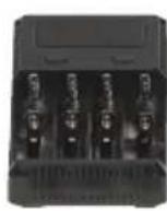
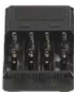
3.5 One charger (P.no. 10208360)
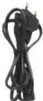
3.6 One USB connecting cable (A plug to B plug) (P.no. 10008312)
3.7 One short instructions
3.8 One calibration certificate

text_image
3.1 3.2 3.3 3.4 3.5 BEVERIFUS PV 2 BEVERIFUS VOLAR 0.0 + - +/-
natural_image
Three types of electrical clamps in black, red, and pink colors, arranged side by side (no text or symbols visible)
natural_image
Two black and red cables with connectors, no visible text or symbols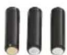
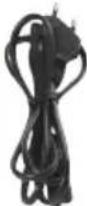
3.6

4. Optional accessories
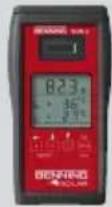
4.1 Insolation and temperature measuring instrument BENNING SUN 2 for measuring the insolation (W/m²), the PV module temperature and the ambient temperature (P.no. 050420)
4.2 Temperature sensor with suction cup for BENNING SUN 2 for attachment to the rear of the PV module (P.no. 050424)
4.3 PV module holder for BENNING SUN 2 for safe attachment to the PV module (P.no. 050425)
4.4 Test badges "next test", 300 pieces (P.no. 756212)
4.1 4.2

text_image
BENNING SUN 2 789 36° 4.4 SEN PV Installer SEK new Prüfung BENNING SOLAR Renewable System 100% 100% 100% 100% 100% 100% 100% 100% 100% 100% 100% 100% 100% 100% 100% 100% 100% 100% 100% 100% 100% 100% 100% 100% Renewable Test 100% 100% 100% 100% 100% 100% 100% 100% 100% 100% 100% 100% 100% 100% 100% 100% Renewable Test 100% 100% 100% 100% 100% Renewable Test 100% 100% 100% 100% 100% 100% Renewable Test 100% 100% 100% 100% 100% 100% Renewable Test 100% 100% 100% 100% 100% 100% Renewable Test 100% 100% 100% 100% 100% 100% Renewable TES Renewable TES Renewable TES Renewable TES Renewable TES Renewable TES Renewable TES Renewable TES Renewable TES Renewable TES Renewable TES Renewable TES Renewable TES Renewable TES Renewable TES Renewable TES Renewable TES Renewable SED Renewable SED Renewable SED Renewable SED Renewable SED Renewable SED Renewable SED Renewable SED Renewable SED Renewable SED Renewable SED Renewable SED Renewable SED Renewable SED Renewable SED Renewable SED Renewable SED Renewtable SED Renewtable SED Renewtable SED Renewtable SED Renewtable SED Renewtable SED Renewtable SED Renewtable SED Renewtable SED Renewtable SED Renewtable SED Renewtable SED Renewtable SED Renewtable SED Renewtable SED Renewtable SED Renewtable SED Reneck 255-2565. Unit description
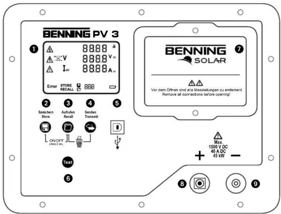
① Digital display
② -key
3 -y
4 -y
⑤ USB socket
6 -taste
⑦ Battery compartment
⑧ + PV test socket, positive
⑨ - PV test socket, negative
text_image
BENNING PV 3 1 88.88 V 88.88 V∞ I∞ 88.88 A∞ Error STORE RECALL 888 2 Speichern Store 3 Aufrufen Recall 4 Senden Transmit ON/OFF press 2 sec. D Test 6 BENNING SOLAR 7 Vor dem Öffnen sind alle Messleitungen zu entfernen! Remove all connections before opening! Max. 1500 V DC 40 A DC 45 kW - 8 9Press and hold the buttons ② and ③ for 2 seconds to switch the BENNING PV 3 on or off.
5.2 Key functions
| Key Press once Press + hold | ||
 | Switches the device ON/OFF | |
 | Store: stores the measuring results, next storage location in recall mode | |
 | Recall: calls measured values, previous storage location in recall mode | |
 | Completely deletes the measured value memory | |
 | Sends measured value memory to USB port | |
 | Starts measurement | |
5.3 Coupling with BENNING SUN 2 (optional accessories)


5.4 Activating/deactivating the radio transmission of the BENNING SUN 2

To activate/deactivate the radio transmission, press and hold the -key of the BENNING SUN 2 and simultaneously press the -key.
A flashing triangle ▼ above the -key shows that the radio transmission has been enabled.
Note:
The automatic switch-off ("APO") is enabled.
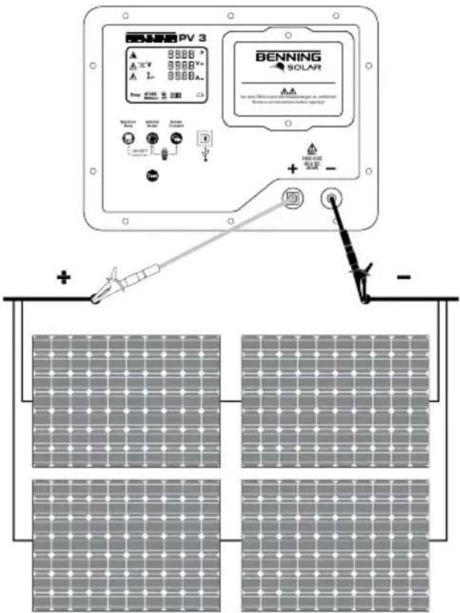
5.5 Measurements on the PV generator
- Connect the BENNING PV 3 to the PV generator by means of the included measuring leads.
- The PV open-circuit voltage is measured automatically if a DC voltage is applied.
- In case of reversed polarity of the DC voltage, the polarity indication is flashing and the “×” symbol is shown on the display ①.
- As soon as a voltage of > 30 V is applied, the ⚠ warning symbol is flashing. Attention! Dangerous voltage ①!
- Press the Testkey 6 to start the automatic measurement.
- The measured values will be shown on the display ① for approx. 20 seconds or until a key is pressed.
Note:
If the DC voltage is applied with reversed polarity or outside the measuring range (< 5 V or > 1500 V), the measurement is blocked.

Max.
Uo/c ≤ 1500 V
Is/c ≤ 40 A
P ≤ 45 kW
text_image
BENNING PV 3 8888 A 1V 8888 V+ A 1- 8888 A- BENNING SOLAR Power Supply Control Power Supply Control Power Supply Control Power Supply Control Power Supply Control Power Supply Control Power Supply Control Power Supply Control Power Supply Control Power Supply Control Power Supply Control Power Supply Control Power Supply Control Power Supply Control Power Supply Control Power Supply Control Power Supply Control Power Supply Control Power Supply Control Power Supply Control Power Supply Control Power Supply Control Power Supply Control Power Supply Control Power Supply Control Power Supply Condition Power Supply Condition Power Supply Condition Power Supply Condition Power Supply Condition Power Supply Condition Power Supply Condition Power Supply Condition Power Supply Condition Power Supply Condition Power Supply Condition Power Supply Condition Power Supply Condition Power Supply Condition Power Supply Condition Power Supply Condition Power Supply Condition Power Supply Condition Power Supply Condition Power Supply Condition Power Supply Condition Power Supply Condition Power Supply Condition Power Supply Condition Power Supply Condition Power Supply Conditions Power Supply Conditions Power Supply Conditions Power Supply Conditions Power Supply Conditions Power Supply Conditions Power Supply Conditions Power Supply Conditions Power Supply Conditions Power Supply Conditions Power Supply Conditions Power Supply Conditions Power Supply Conditions Power Supply Conditions Power Supply Conditions Power Supply Conditions Power Supply Conditions Power Supply Conditions Power Supply Conditions Power Supply Conditions Power Supply Conditions Power Supply Conditions Power Supply Conditions Power Supply Conditions Power Supply Conditions Power Supply Condition Power Supply Condition Power Supply Condition Power Supply Condition Power Supply Condition Power Supply Condition Power Supply Condition Power Supply Condition Power Supply Condition Power Supply Condition Power Supply Condition Power Supply Condition Power Supply Condition Power Supply Condition Power Supply Condition Power Supply Condition Power Supply Condition Power Supply Condition Power Supply Condition Power Supply Condition Power Supply Condition Power Supply Condition Power Supply Condition Power Supply Condition Power Supply Directional Position (P) + - - -5.6 Storing measured values

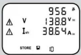
Press the key ② to store the displayed measured values to the next free storage location. The BENNING PV 3 can store up to 999 display indications.
text_image
956 # V 138.8 V Isc 38.64A STORE ☐ ☐Successful storage will be confirmed by the "STORE" symbol. If there is no more storage location available, an acoustic signal is emitted.
5.7 Reading out the measured value memory via the USB interface
Install the hardware driver and the program „BENNING SOLAR Datalogger“ on your PC once.
The latest version is available for free download on the product page of the BENNING PV 3.
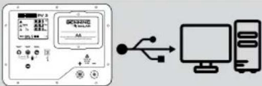 | Connect the BENNING PV 3 to your PC by means of the USB connecting cable. The hardware driver is installed automatically on a free COM port. |
 | Start the “BENNING SOLAR Datalogger” software on your PC and select the COM port used. Please refer to the integrated help function for further information. |
 | Press and hold the key 4 of the BENNING PV 3 for some seconds until the download starts. |
 | By default, the measured values are stored in CSV format. Open the file using a spreadsheet program (e. g. MS Excel®). |
6. Online information
6.1 Operating manual and further information
To download the detailed operating manual and further information, please visit the product page of the BENNING PV 3 at http://tms.benning.de/pv3
6.2 BENNING SOLAR Datalogger (PC software)
To download the PC software „BENNING SOLAR Datalogger“, please visit the product page of the BENNING PV 3 at http://tms.benning.de/pv3
7. Calibration and Support
Benning guarantees compliance with the technical and accuracy specifications stated in the operating manual for the first 12 months after the delivery date. To maintain the specified precision of the measurement results, the instrument must be recalibrated at regular intervals by our factory service. We recommend a recalibration interval of one year. Send the appliance to the following address:
Technical Support/Helpdesk:
natural_image
Two types of electrical clamps with black and red wires, no visible text or symbols
natural_image
Two black and red cables with connectors, no visible text or symbols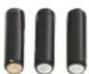
3.6

4. Accessoires en option
text_image
BENNING PV 3 8988 A 8988 V 1- 8988 A. BENNING SOLAR for the solar difference and the corresponding voltage in the circuit Rustices and current measurements are clearly marked + - + - -text_image
Diagram showing a device connected to a computer via USB cable, with labeled ports and connection points.Service commercial :
natural_image
Two sets of black and red clamps with probe clips, no text or symbols visible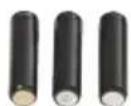
3.6

text_image
BENNING SUN 2 789 N 36° OK HOLD 100 BENNING SOLAR P-Intervention Systemes BEN PV Install Chrysler 400 GB/1.5GHz Dissipation Electrical Systemes Power, DC, IGBT, and others DC/DC voltage system Dissipation device, multi-wattled switching system. BENING SUN 2 BEN PV Install Chrysler
natural_image
Close-up of a handheld electronic device with wires and a circular lens (no visible text or symbols)4.4

4.3