
C10FSB - Saw HiKOKI - Free user manual and instructions
Find the device manual for free C10FSB HiKOKI in PDF.

| Product type | Radial miter saw |
| Brand | HiKOKI |
| Model | C10FSB |
| Max cutting capacity (0°) | 85 mm × 312 mm |
| Max cutting capacity (miter 45°) | 85 mm × 218 mm |
| Max cutting capacity (bevel 45° left) | 55 mm × 305 mm |
| Blade dimensions | 255 mm × 30 mm × 2.3 mm |
| Miter angle | Right 0°-57°, Left 0°-45° |
| Bevel angle | 0°-45° (right and left) |
| No-load speed | 3800 min⁻¹ |
| Power | 1090 W |
| Voltage | 110 V or 230 V depending on region |
| Net weight | 19.5 kg |
| Dimensions (L × D × H) | 545 mm × 1050 mm × 615 mm |
| Included accessories | TCT blade 255 mm, chip collection bucket, 10 mm wrench, vise assembly, stand, auxiliary guide |
| Functions | Miter cut, bevel, compound, sliding cut, grooving |
| Safety | Lower guard, head lock, overload protection device |
| Maintenance | Monthly lubrication, carbon brush replacement, regular cleaning |
| Cut materials | Aluminum, wood and similar materials (no ferrous metals or masonry) |
Frequently Asked Questions - C10FSB HiKOKI
User questions about C10FSB HiKOKI
0 question about this device. Answer the ones you know or ask your own.
Ask a new question about this device
Download the instructions for your Saw in PDF format for free! Find your manual C10FSB - HiKOKI and take your electronic device back in hand. On this page are published all the documents necessary for the use of your device. C10FSB by HiKOKI.
USER MANUAL C10FSB HiKOKI
natural_image
Technical line drawing of a mechanical cutting machine (no text or symbols)Read through carefully and understand these instructions before use. Diese Anleitung vor Benutzung des Werkzeugs sorgfältig durchlesen und verstehen. Lire soigneusement et bien assimiler ces instructions avant usage. Prima dell'uso leggere attentamente e comprendere queste instruzioni. Deze gebruiksaanwijzing s.v.p. voor gebruik zorgvuldig doorlezen. Leer cuidadosamente y comprender estas instrucciones antes del uso. Antes de usar, leia com cuidado para assimilar estas instruções. Διαβάστε προσεκτικά και κατανοήσετε αυτέσ τισ οδηγίεσ πριν τη χρήση.

Handling instructions Bedienungsanleitung Mode d'emploi Instruzioni per l'uso Gebruiksaanwijzing Instrucciones de manejo Instruções de uso Οδηγίεσ χειρισμού
1
2
3
4

5
6
7
8
9
10
11
12
13
natural_image
Technical line drawing of a mechanical clamp or bracket with a curved arrow indicating direction (no text or symbols)
natural_image
Illustration of a mechanical assembly with a tool and directional arrow (no text or symbols)
LASER RADIATION
Do not show in
the laser line.
(laser beam)
LASER CLASSII Po<3mW,
C6=3. (lambda)=654nm
Time basis 0.25s
DIN EN 60825-1:2001-11
C417607
14 15
16 17
18 19
20
21
22 23
| English Deutsch Français | |||
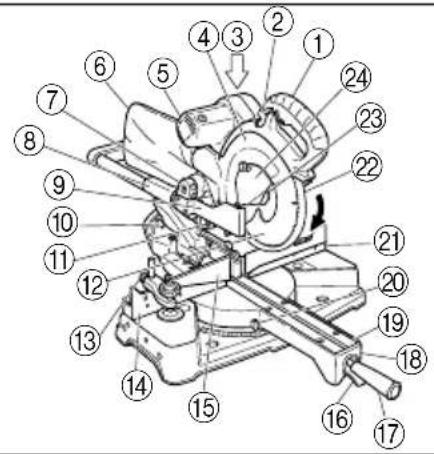
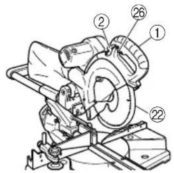
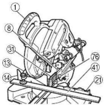
| 1 | Handle Griff Poignée | ||
| 2 | Lever (A) Hebel (A) Levier (A) | ||
| 3 | Motor Head Motorkopf Tête de moteur | ||
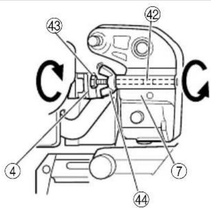
| 4 | Gear Case Getriebegehäuse Réducteur | ||
| 5 | Motor Motor Moteur | ||
| 6 | Dust Bag Staubbeutel | Bacquet de réception des copeaux | |
| 7 | Hinge Scharnier Charnière | ||
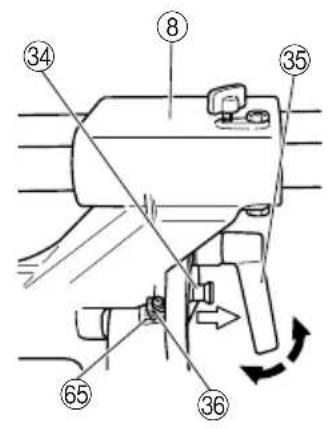
| 8 | Holder (A) Halter (A) Support (A) | ||
| 9 | Sub Cover Unterabdeckung Capot secondaire | ||
| 10 | Indicator (For right bevel scale) | Zeiger (Für rechte Indicateur (Pour Schrägschnittskala) | l'échelle de biseau à droite) |
| 11 | Laser Marker (Only C10FSH) | Lasermarkierer (Nur C10FSH) | Marqueur à laser (C10FSH seulement) |
| 12 | Saw Blade | Sägeblatt Lame de scie | |
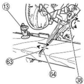
| 13 | Vise Assembly | Schraubstocksatz | Ensemble d'étau |
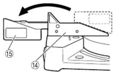
| 14 | Fence (B) Gitter (B) Guide (B) | ||
| 15 | Sub Fence Hilfsführung | Guide auxiliaire | |
| 16 | Lever | Hebel | Levier |
| 17 | Side Handle | Seitengriff Poignée latérale | |
| 18 | Turntable Drehbühne | Plaque tournante | |
| 19 | Table Insert | Tischeinsatz Plaque d'insertion | |
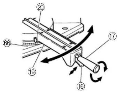
| 20 | Indicator (For miter scale) | Zeiger (Für Gehrungsskala) | Indicateur (Pour l'échelle d'onglet) |
| 21 | Fence (A) | Gitter (A) | Guide (A) |
| 22 | Lower Guard | Unterer Schutz | Guide inférieur |
| 23 | Washer (B) | Unterlegscheibe (B) | Rondelle (B) |
| 24 | Spindle Cover | Spindelabdeckung | Couvercle de l'arbre |
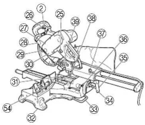
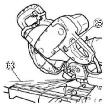
| 25 | Switch (For laser marker) (Only C10FSH) | Schalter (Für Lasermarkierer) (nur C10FSH) | Interrupteur (Pour marqueur à laser) (C10FSH seulement) |
| 26 | Trigger Switch | Auslöserschalter | Interrupteur à détente |
| 27 | 5 mm Screw | Schraube, 5 mm Vis de 5 mm | |
| 28 | Nameplate | Typenschild Plaque signalétique | |
| 29 | Spindle Lock | Spindelhebel | Verrou en fuseau |
| 30 | Belt Cover | Riemenabdeckung | Cache de courroie |
| 31 | Guard | Schutz | Protection |
| 32 | Base | Grundplatte | Socle |
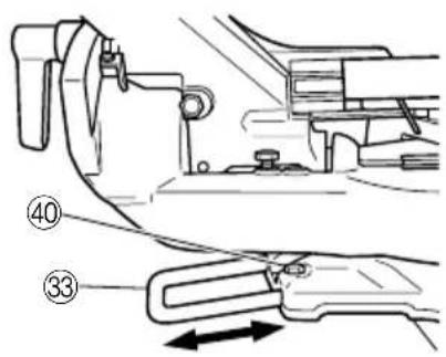
| 33 | Holder | Halter | Support |
| 34 | Fixing Pin | Fixierstift Goupille de fixation | |
| 35 | Clamp Lever | Klemmhebel | Levier de serrage |
| 36 | Indicator (For left bevel scale) | Zeiger (Für linke Schrägschnittskala) | Indicateur (Pour échelle de biseau à gauche) |
| 37 | Slide Securing Knob | Führungssicherungsknopf | Bouton de fixation du chariot |
| 38 | Adjuster (For laser marker) (Only C10FSH) | Einstellung (Für Lasermarkierer) (Nur C10FSH) | Ajusteur (Pour marqueur à laser) (C10FSH seulement) |
| 39 | Locking Pin | Verriegelungsstift | Goupille de verrouillage |
| 40 | 6 mm Bolt | 6-mm-Schraube | Boulon 6 mm |
| 41 | Workpiece | Werkstück | Pièce |
| 42 | 8 mm Hexagon Socket Set Screw | Innensechskant-Stellschraube, 8 mm hexagonale de 8 mm | Vis boulonnée à douille |
| 43 | mm Depth Adjustment Bolt | 8-mm-Tiefeneinstellschraube | Boulon de réglage de profondeur de 8 mm |
| 448 | mm Wing Nut Flügelschraube, 8 m | m Ecrou à ailettes de 8 mm | |
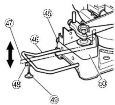
| 45 | 6 mm Knob Bolt (Optional accessory) | Knopfschraube, 6 mm Vis moletée (Sonderzubehör) (Accessoire en option) | de 6 mm |
| 46 | Holder (Optional accessory) Halter (Sonderzubehör) Support (Accessoire en option) | en option) | |
| 47 | Steel Square Stahlwinkel Equerre en acier | ||
| 48 | 6 mm Wing Nut (Optional accessory) | Flügelschraube, 6 mm Ecrou à ailettes de 6 mm (Sonderzubehör) (Accessoire en option) | |
| 49 | Height Adjustment Bolt 6 mm Höheneinstellschraube, 6 mm Boulon (Optional accessory) (Sonderzubehör) de 6 mm (Accessoire en option) | de réglage de la hauteur | |
| 50 | Base Surface Grundfläche Surface du socle | ||
| 51 | Stopper (Optional accessory) | Anschlag (Sonderzubehör) | Butée (Accessoire en option) |
| 52 | 6 mm Knob Bolt (Optional accessory) | Knopfschraube, 6 mm Vis moletée de 6 mm (Sonderzubehör) (Accessoire en option) | |
| 53 | Sub Fence (A) | Hilfsführung (A) | Guide auxiliaire (A) |
| 54 | 6 mm Bolt | Schraube, 6 mm | Boulon de 6 mm |
| 55 | Screw Holder | Schraubenhalter | Support de vis |
| 56 | 6 mm Knob Bolt | 6-mm-Knopfschraube | Vis moletée de 6 mm |
| 57 | V-Groove Keilnut Rainure en V | ||
| 58 | Groove Nut Rainure | ||
| 59 | Fence Gitter Guide | ||
| 60 | 6 mm Knob Bolt | 6-mm-Knopfschraube | Vis moletée de 6 mm |
| 61 | Vise Plate | Schraubstockbacke | Talon |
| 62 | Knob Knopf Bouton | ||
| 63 | Laser line Laserlinie Raie laser | ||
| 64 | Groove Nut Rainure | ||
| 65 | Bevel Scale | Schrägschnittskala | Echelle de biseau |
| 66 | Miter Scale Gehrungsskala | Echelle d'onglet | |
| 67 | Crown molding Vise Ass'y (Optional accessory) Kronenform | Schraubstocksatz für (Sonderzubehör) | Ensemble d'étau de corniche à courbe complexe (Accessoire en option) |
| 68 | 6 mm Wing Nut (Optional accessory) | Flügelmutter, 6 mm (Sonderzubehör) (Accessoire en option) | Ecrou à ailettes de 6 mm |
| 69 | Crown molding Stopper (L) (Optional accessory) | Kronenformanschlag (L) (Sonderzubehör) | Butée de corniche à courbe complexe (L) (Accessoire en option) |
| 70 | Crown molding Stopper (R) Kronenformanschlag (R) Butée (Optional accessory) (Sonderzubehör) | (Sonderzubehör) | de corniche à courbe complexe (R) (Accessoire en option) |
| 71 | Crown molding | Kronenform | Corniche à courbe complexe |
| 72 | 10 mm Box Wrench | 10 mm Steckschüssel | Clé à écrous de 10 mm |
| 73 | Bolt Schraube Boulon | ||
| 74 | Washer (A) | Unterlegscheibe (A) | Rondelle (A) |
| 75 | Wear limit line | Verschleißgrenze | Repère de limite d'usure |
| 76 | 6 mm Knob Bolt | 6-mm-Knopfschraube | Vis moletée de 6 mm |
| Italiano Nederlands Español | |||
| 1Manico Greep Empuñaradura | |||
| 2Leva (A) Hendel (A) Palanca (A) | |||
| 3Testa motore Motorkop Cabezal del motor | |||
| 4Cassa ingranaggi Tandwielkast Caja de engranajes | |||
| 5Motore Motor Motor | |||
| 6Raccoglipolvere Stofzak Bolsa para e polvo | |||
| 7Cardine Scharnier Bisagra | |||
| 8Supporto (A) Houder (A) Soporte (A) | |||
| 9Sottocoperchio Hulpkap Cubierta secundaria | |||
| 10Indicatore (Per la scala di smussatura destra) | Indicator (Voor rechter afschuiningsschaal) | Indicator (Para escala en bisel derecho) | |
| 11Marcatore laser (Solo C10FSH) | Lasermkeerinrichting (Alleen voor C10FSH) | Marcador láser (Sólo C10FSH) | |
| 12Lama sega | Zaagblad | Cuchilla de sierra | |
| 13Gruppo morsa | Bankschroef | Conjunto del tornillo de carpintero | |
| 14Guida de appoggio (B) | Geleider (B) | Protección (B) | |
| 15Guida secondaria | Sub-geleider | Tope-guía secundario | |
| 16Leva Hendel Palanca | |||
| 17Manico laterale Zijgreep Asa lateral | |||
| 18Piatto girevole Draaitafel Plataforma | |||
| 19Inserimento tavola | Tafel-inzetstuk | Inserto de mesa | |
| 20Indicatore (Per la scala di quartabuono) | Indicator (Voor verstekschaal) | Indicator (Para escala de ingletes) | |
| 21Guida de appoggio (A) | Geleider (A) | Protección (A) | |
| 22Protezione inferiore | Onderste afscherming | Protector inferior | |
| 23Rondella (B) | Sluitring (B) | Arandela (B) | |
| 24Coperchio dell'alberino | Drijfas-afdekking | Cubierta de husillo | |
| 25Interruttore (Per marcatore laser) (Solo C10FSH) | Schakelaar (Voor lasermkeerinrichting) (Alleen voor C10FSH) | Interruptor (Para marcador láser) (Sólo C10FSH) | |
| 26Interruttore a grilletto | Startschakelaar | Gatillo | |
| 27Vite da 5 mm | 5 mm schroef | Tornillo de 5 mm | |
| 28Targhetta | Specificatieplaatje | Placa de identificación | |
| 29Fermo dell'alberino | Spilvergrendeling | Seguro del eje | |
| 30Copricinghia Riemafdekking | Cubierta de la correa | ||
| 31Schermo protettivo Bescherming Protector | |||
| 32Base Basis Base | |||
| 33Supporto Houder Soporte | |||
| 34Perno di fissaggio | Bevestigingspen | Pasador de fijación | |
| 35Leva morsetto | Klemhendel | Palanca de fijación | |
| 36Indicatore (Per la scala di smussatura sinistra) | Indicator (Voor linker afschuinschaal) | Indicator (para escala en bisel izquierda) | |
| 37Manopola di fissaggio slitta Schuifvastzetknop | Perilla de inmovilización de deslizamiento | ||
| 38Regolatore (Per marcatore laser) (Solo C10FSH) | Afsteller (Voor lasermkeerinrichting) (Alleen voor C10FSH) | Ajustador (Para marcador láser) (Sólo C10FSH) | |
| 39Perno di blocco | Vergrendelpen | Pasador de bloqueo | |
| 40Bullone da 6 mm | 6 mm bout | Perno de 6 mm | |
| 41Pezzo da lavorare | Werkstuk | Pieza de trabajo | |
| 42 | Vite di fissaggio a testa esagonale da 8 mm hexagonal 8 | 8 mm inbus-stelschroef mm | Prisionero de cabeza hueca |
| 43 | Bullone di regolazione profondità da 8 mm | 8 mm diepte-stelbout | Perno de ajuste de profundidad de 8 mm |
| 44 | Dado ad alette da 8 mm 8 mm vleugelmoer Tuerca de aletas de 8 mm | ||
| 45 | Bullone a manopola da 6 mm 6 mm knopbout Perno de perilla de 6 mm (Accessorio opzionale) (Optioneel toebehoren) (Accesorio opcional) | ||
| 46 | Supporto (Accessorio opzionali) | Houder (Optionele toebehoren) | Soporte (Accessorio opcionales) |
| 47 | Quadrato di acciaio Stalen winkelhaak Escuadra de acero | ||
| 48 | Dado ad alette da 6 mm 6 mm vleugelmoer Tuerca de aletas de 6 mm (Accessorio opzionale) (Optioneel toebehoren) (Accesorio opcional) | ||
| 49 | Bullone di regolazione altezza da 6 mm (Accessorio opzionale) | Hoogte-afstelbout 6 mm Perno de (Optioneel toebehoren) 6 mm (Accesorio opcional) | ajuste de altura de |
| 50 | Superficie della base | Voetplaat | Superficie de la base |
| 51 | Fermo (Accessorio opzionali) | Aanslag (Optionele toebehoren) | Retén (Accessorio opcionales) |
| 52 | Bullone a manopola da 6 mm 6 mm knopbout Perno de perilla de 6 mm (Accessorio opzionale) (Optioneel toebehoren) (Accesorio opcional) | ||
| 53 | Guida secondaria (A) | Subgeleider (A) | Tope-guía secundario (A) |
| 54 | Bullone da 6 mm 6 mm Bout | Perno de 6 mm | |
| 55 | Portavite | Schroefhouder | Sujetador de rosca |
| 56 | 6 mm Bullone a manopola | 6 mm bout | 6 mm Perno de perilla |
| 57 | Scanalatura a V | V-groef | Ranura en V |
| 58 | Scanalatura Groef Ranura | ||
| 59 | Guida di appoggio Geleider | Protrección | |
| 60 | 6 mm Bullone a manopola | 6 mm bout | 6 mm Perno de perilla |
| 61 | Piastra morsa | Klemplaat | Placa de tornillo |
| 62 | Manopola Knop Perilla | ||
| 63 | Linea laser | Laserstreep | Línea de láser |
| 64 | Scanalatura Groef Ranura | ||
| 65 | Scala di smussatura | Afschuinschaal | Escala en bisel |
| 66 | Scala di quartabuono | Verstekschaal | Escala de ingletes |
| 67 | Gruppo morsa di modanatura a corona (Accessorio opzionale) | Kroonvormklem (Optioneel toebehoren) | Conj. de tornillo de carpintero para moldura en vértice (Accesorio opcional) |
| 68 | Dado ad alette da 6 mm 6 mm vleugelmoer Tuerca de aletas de 6 mm (Accessorio opzionale) (Optioneel toebehoren) (Accesorio opcional) | ||
| 69 | Fermo per modanatura a corona (L) (Accessorio opzionale) | Kroonvormstopper (L) (Optioneel toebehoren) | Retén de moldura en vértice (L) (Accesorio opcional) |
| 70 | Fermo per modanatura a corona (R) (Accessorio opzionale) | Kroonvormstopper (R) (Optioneel toebehoren) | Retén de moldura en vértice (R) (Accesorio opcional) |
| 71 | Modanatura a corona | Kroonvorm | Moldura en vértice |
| 72 | Chiave chisa de 10 mm | 10 mm naafbussleutel | Llave de tubo de 10 mm |
| 73 | Bullone Schroef Perno | ||
| 74 | Rondella (A) | Sluitring (A) | Arandela (A) |
| 75 | Riga di limite usura | Slijtagegrens | Línea de límite de desgaste |
| 76 | 6 mm Bullone a manopola | 6 mm bout | 6 mm Perno de perilla |
WARNING! When using electric tools, basic safety precautions should always be followed to reduce the risk of fire, electric shock and personal injury, including the following.
Read all these instructions before operating this product and save these instructions.
For safe operations:
- Keep work area clean. Cluttered areas and benches invite injuries.
- Consider work area environment. Do not expose power tools to rain. Do not use power tools in damp or wet locations. Keep work area well lit. Do not use power tools where there is risk to cause fire or explosion.
- Guard against electric shock. Avoid body contact with earthed or grounded surfaces (e.g. pipes, radiators, ranges, refrigerators).
- Keep children and infirm persons away. Do not let visitors touch the tool or extension cord. All visitors should be kept away from work area.
- Store idle tools. When not in use, tools should be stored in a dry, high or locked up place, out of reach of children and infirm persons.
- Do not force the tool. It will do the job better and safer at the rate for which it was intended.
- Use the right tool. Do not force small tools or attachments to do the job of a heavy duty tool. Do not use tools for purposes not intended; for example, do not use circular saw to cut tree limbs or logs.
- Dress properly. Do not wear loose clothing or jewelry, they can be caught in moving parts. Rubber gloves and non-skid footwear are recommended when working outdoors. Wear protecting hair covering to contain long hair.
- Use eye protection. Also use face or dust mask if the cutting operation is dusty.
- Connect dust extraction equipment. Cutting operation by this slide compound miter saw may produce considerable amount of dust from extraction duct on fixed guard. (Dust material: Wood or Aluminium) If devices are provided for the connection of dust extraction and collection facilities ensure these are connected and properly used.
- Do not abuse the cord. Never carry the tool by the cord or yank it to disconnect it from the receptacle. Keep the cord away from heat, oil and sharp edges.
- Secure work. Use clamps or a vise to hold the work. It is safer than using your hand and it frees both hands to operate tool.
- Do not overreach. Keep proper footing and balance at all times.
- Maintain tools with care. Keep cutting tools sharp and clean for better and safer performance. Follow instructions for lubrication and changing accessories. Inspect tool cords periodically and if damaged, have it repaired by authorized service center. Inspect extension cords periodically and replace, if damaged. Keep handles dry, clean, and free from oil and grease.
- Disconnect tools. When not in use, before servicing, and when changing accessories such as blades, bits and cutters.
- Remove adjusting keys and wrenches. Form the habit of checking to see that keys and adjusting wrenches are removed from the tool before turning it on.
-
Avoid unintentional starting. Do not carry a plugged-in tool with a finger on the switch. Ensure switch is off when plugging in.
-
Use outdoor extension leads. When tool is used outdoors, use only extension cords intended for outdoor use.
- Stay alert. Watch what you are doing. Use common sense. Do not operate tool when you are tired.
- Check damaged parts. Before further use of the tool, a guard or other part that is damaged should be carefully checked to determine that it will operate properly and perform its intended function. Check for alignment of moving parts, free running of moving parts, breakage of parts, mounting and any other conditions that may affect its operation. A guard or other part that is damaged should be properly repaired or replaced by an authorized service center unless otherwise indicated in this handling instructions. Have defective switches replaced by an authorized service center. Do not use the tool if the switch does not turn it on and off.
- Warning The use of any accessory or attachment, other than those recommended in this handling instructions, may present a risk of personal injury.
- Have your tool repaired by a qualified person. This electric tool is in accordance with the relevant safety requirements. Repairs should only be carried out by qualified persons using original spare parts. Otherwise this may result in considerable danger to the user.
PRECAUTIONS ON USING SLIDE COMPOUND MITER SAW
- Keep the floor area around the machine level. Well maintained and free of loose materials e.g. chips and cut-offs.
- Provide adequate general or localized lighting.
- Do not use power tools for applications other than those specified in the handling instructions.
- Repairing must be done only by authorized service facility. Manufacturer is not responsible for any damages and injuries due to the repair by the unauthorized persons as well as the mishandling of the tool.
- To ensure the designed operational integrity of power tools, do not remove installed covers or screws.
- Do not touch movable parts or accessories unless the power source has been disconnected.
- Use your tool at lower input than specified on the nameplate; otherwise, the finish may be spoiled and working efficiency reduced due to motor overload.
- Do not wipe plastic parts with solvent. Solvents such as gasoline, thinner, benzine, carbon tetrachloride, alcohol, may damage and crack plastic parts. Do not wipe them with such solvent. Clean plastic parts with a soft cloth lightly dampened with soapy water.
- Use only original HiKOKI replacement parts.
- This tool should only be disassembled for replacement of carbon brushes.
- The exploded assembly drawing on this handling instructions should be used only for authorized service facility.
- Never cut ferrous metals or masonry.
- Adequate general or localized lighting is provided. Stock and finished workpieces are located close to the operators normal working position.
- Wear suitable personal protective equipment when necessary, this could include: Hearing protection to reduce the risk of induced hearing loss. Eye protection to reduce the risk of injuring an eye. Respiratory protection to reduce the risk of inhalation of harmful dust.
Gloves for handling saw blades (saw blades shall be carried in a holder wherever practicable) and rough material.
- The operator is adequately trained in the use, adjustment and operation of the machine.
- Refrain from removing any cut-offs or other parts of the workpiece from the cutting area whilst the machine is running and the saw head is not in the rest position.
- Never use the slide compound miter saw with its lower guard locked in the open position.
- Ensure that the lower guard moves smoothly.
- Do not use the saw without guards in position, in good working order and properly maintained.
- Use correctly sharpened saw blades. Observe the maximum speed marked on the saw blade.
- Do not use saw blades which are damaged or deformed.
- Do not use saw blades manufactured from high speed steel.
- Use only saw blades recommended by HiKOKI. Use of saw blade comply with EN847-1.
- The saw blades should be from 235 mm to 255 mm external diameter ranges.
- Select the correct saw blade for the material to be cut.
-
Never operate the slide compound miter saw with the saw blade turned upward or to the side.
-
Ensure that the workpiece is free of foreign matter such as nails.
- Replace the table insert when worn.
- Do not use the saw to cut other than aluminium, wood or similar materials.
- Do not use the saw to cut other materials than those recommended by the manufacturer.
- Blade replacement procedure, including the method for repositioning and a warning that this must be carried out correctly.
- Connect the slide compound miter saw to a dust collecting device when sawing wood.
- Take care when slotting.
- When transporting or carrying the tool, do not grasp the holder. Grasp the handle instead of the holder.
- Start cutting only after motor revolution reaches maximum speed.
- Promptly cut OFF the switch when abnormality observed.
- Shut off power and wait for saw blade to stop before servicing or adjusting tool.
- During a miter or bevel cut the blade should not be lifted until it has stopped rotation completely.
- During slide cutting operation, the saw must be pushed and slid away from the operator.
- Take all the possibility of residual risks in cutting operation into your consideration, such as the laser radiation to your eyes, the inadvertent access to moving parts on slide mechanical parts on machine and so on.
SPECIFICATIONS
| Max. Cutting Capacity Height × Width | 0° 85 mm × 312 mm | |||
| Miter 45° 85 mm × 218 mm | ||||
| Bevel | Left 45° 55 mm × 305 mm | |||
| Right 45° 30 mm × 305 mm | ||||
| Compound | Bevel (Left) 45° + Miter 45° | 55 mm × 218 mm | ||
| Bevel (Right) 45° + Miter (Left) 31° | 30 mm × 260 mm | |||
| Bevel (Right) 45° + Miter (Right) 45° | 30 mm × 218 mm | |||
| Saw Blade Dimensions (oD × iD × Thickness) | 255 mm × 30 mm × 2.3 mm | |||
| Miter Cutting Angle Right 0° – 57°, Left 0° – 45° | ||||
| Bevel Cutting Angle Right and Left 0° – 45° | ||||
| Compound Cutting Angle | Bevel (Left) 0° – 45° | Miter (Right and Left) 0° – 45° | ||
| Bevel (Right) 0° – 45° | ||||
| Voltage (by areas)* | (110 V, 230 V) ↘ | |||
| Power Input* | 1090 W | |||
| No-Load Speed | 3800 min ^-1 | |||
| Machine Dimensions (Width × Depth × Height) | 545 mm × 1050 mm × 615 mm | |||
| Weight (Net) | 19.5 kg | |||
| Laser Marker(Only Model C10FSH) | Maximum output | Po<3 mW Class II Laser Product | ||
| (lambda) | 654 nm | |||
| Laser medium | Laser Diode | |||
* Be sure to check the nameplate on product as it is subject to change by areas.
STANDARD ACCESSORIES
(1) 255 mm TCT Saw blade (mounted on tool) ..... 1
(2) Dust bag 1
(3) 10 mm Box wrench .... 1
(4) Vise Assembly 1
(5) Holder 1
(6) Sub Fence (A) 1
Standard accessories are subject to change without notice.
OPTIONAL ACCESSORIES (SOLD SEPARATELY)
(1) Extension Holder and Stopper
(2) Saw blade 255 mm TCT Saw blade (Total teeth: 72)
(3) Crown molding Vise Ass'y (Include Crown molding Stopper (L))
(4) Crown molding Stopper (L)
(5) Crown molding Stopper (R)
Optional accessories are subject to change without notice.
APPLICATION
○Cutting various types of aluminium sash and wood.
UNPACKING
○Carefully unpack the power tool and all related items (standard accessories).
○Check carefully to make certain all related items (standard accessories) are present.
PRIOR TO OPERATION
1. Power source
Ensure that the power source to be utilized conforms to the power requirements specified on the product nameplate.
2. Power switch
Ensure that the power switch is in the OFF position. If the plug is connected to a receptacle while the trigger switch is in the ON position, the power tool will start operating immediately, inviting serious accident.
3. Extention cord
When the work area is removed from the power source, use an extension cord of sufficient thickness and rated capacity. The extension cord should be kept as short as practicable.
4. When the power tool is prepared for shipping, its main parts are secured by a locking pin
Move the handle slightly so that the locking pin can be disengaged.
During transport, lock the locking pin into the gear case (Fig. 4).
5. Attach the dust bag to the main unit (Fig. 1)
6. Installation
Ensure that the machine is always fixed to bench.
Attach the power tool to a level, horizontal work bench. Select 8 mm diameter bolts suitable in length for the thickness of the work bench.
Bolt length should be at least 25 mm plus the thickness of the work bench.
For example, use 8 mm × 65 mm bolts for a 25 mm thick work bench.
ADJUSTING THE POWER TOOL PRIOR TO USE
CAUTION
Make all necessary adjustments before inserting the plug in the power source.
1. Check to see that the lower guard operates smoothly CAUTION
○This slide compound miter saw is equipped with a saw head lock as safety device.
☐ To lower the saw head to cut, the lock must be released by pressing the lever (A) with your thumb.
(1) When you push down the handle while pushing the lever (A), check that the lower guard revolves smoothly (Fig. 5).
(2) Next, check that the lower guard returns to the original position when the handle is raised.
2. Checking the saw blade lower limit position (Fig. 7)
Check that the saw blade can be lowered 10 mm to 11 mm below the table insert. If necessary, adjust as follows:
(1) Loosen the 8 mm wing nut.
(2) Insert your 6 mm hexagon bar wrench from behind of the tool and turn the 8 mm hexagon socket set screw to the left (counterclockwise) viewed from behind of the tool.
(3) Turn the 8 mm depth adjustment bolt, change the height where the bolt head and the gear case contacts, and adjust the lower limit position of the saw blade. One turn of the 8 mm depth adjustment bolt changes the lower limit position of the saw blade by about 8 mm, and this information can be used as a rough guide.
(4) Turn the 8 mm hexagon socket set screw to the right (clockwise) as viewed from behind of the tool, and let it softly contact the tip of the 8 mm depth adjustment bolt.
CAUTION
Adjust the lower limit position so that the saw blade will not cut the turntable or complete cutting cannot be done.
PRACTICAL APPLICATIONS
CAUTION
○It is dangerous to remove or install the workpiece while the saw blade is turning.
○When sawing, clean off the shavings from the turntable.
○If the shavings accumulate too much, the saw blade from the cutting material will be exposed. Never subject your hand or anything else to go near the exposed blade.
1. Tightly secure the material by vise assembly to be cut so that it does not move during cutting
2. Switch operation
Pulling the trigger turns the switch on. Releasing the trigger turns the switch off.
3. Base holder adjustment (Fig. 3)
Loosen the 6 mm bolt with the supplied 10 mm box wrench. Adjust the base holder until its bottom surface contacts the bench or the floor surface.
4. Cutting a groove on the guard
Holder (A) has a guard (see Fig. 6) into which a groove must be cut. Loosen the 6 mm knob bolt to retract the guard slightly.
After placing a suitable wooden piece to sit on the fence and the table surfaces, fix it with the vise. After the switch has been turned on and the saw blade has reached maximum speed, slowly lower the handle to cut a groove on the guard.
CAUTION
Do not cut the groove too quickly; otherwise the guard might become damaged.
5. Adjusting the guard (Fig. 6)
(1) In the case of cutting at a right angle or bevel cutting: Loosen the 6 mm knob bolt, bring the guard lightly in contact with the materials to be cut and secure. Align the ink line with the saw blade groove on the guard and begin operations.
(2) In the case of miter cutting or miter cutting plus bevel cutting:
Loosen the 6 mm knob bolt, move the guard to the back, making sure that it is not sticking out from the fence surface.
6. Using the Vise Assembly (Standard accessory) (Fig. 12)
The vise assembly can be mounted on either the left fence (Fence (B)), or the right fence (Fence(A)), and can be raised or lowered according to the height of the workpiece. To raise or lower the vise assembly, first loosen the 6 mm knob bolt. The vise shaft has three locking grooves into which the tip of the 6 mm wing bolt is designed to fit in order to lock the screw holder in the desired position. To ensure that the tip of the 6 mm wing bolt is properly aligned with the desired locking groove on the vise shaft, simply align the upper surface of the fence to either of three V-grooves on the vise shaft surface or to the lower surface of the screw holder. Therefore, the vise assembly can be attached in either of three positions to ensure proper height adjustment.
After adjusting the height, firmly tighten the 6 mm wing bolt; then turn the upper knob, as necessary, to securely attach the workpiece in position.
WARNING
○Always firmly clamp or vise to secure the workpiece to the fence; otherwise the workpiece might be thrust from the table and cause bodily harm.
CAUTION
○Always confirm that the motor head does not contact the vise assembly when it is lowered for cutting. If there is any danger that it may do so, loosen the 6 mm wing bolt and move the vise assembly to a position where it will not contact the saw blade.
7. Positioning the table insert (Fig. 1)
Table inserts are installed on the turntable. When shipping the tool from the factory, the table inserts are so fixed that the saw blade does not contact them. The burr of the bottom surface of the workpiece is remarkably reduced, if the table insert is fixed so that the gap between the side surface of the table insert and the saw blade will be minimum. Before using the tool, eliminate this gap in accordance with the following procedure.
Loosen the three 6 mm machine screws, then secure the left side table insert and temporarily tighten the 6 mm machine screws of both ends. Then fix a workpiece (about 200 mm wide) with the vise assembly and cut it off. After aligning the cutting surface with the edge of the table insert, securely tighten the 6 mm machine screws of both ends.
Remove the workpiece and securely tighten the 6 mm center machine screw. Adjust the right hand table insert in the same way.
CAUTION
○After adjusting the table insert for right angle cutting, the table insert will be cut to some extent if it is used for bevel angle cutting.
When bevel cutting operation is required, adjust the table insert for bevel angle cutting.
8. Confirmation for use of sub fence
This power tool is equipped with a sub fence. In the case of direct angle cutting and right bevel angle cutting, use the sub fence. Then, you can do Left bevel angle cutting, Right bevel angle cutting and Direct angle cutting and realize stable cutting of the material with a wide back face.
WARNING
○In the case of left bevel cutting, turn the sub fence counterclockwise (Fig. 8). Unless it is turned counterclockwise, the main body or saw blade may contact the sub fence, resulting in an injury.
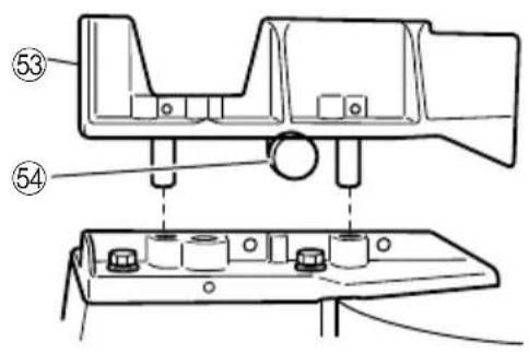
9. Confirmation for use of sub fence (A) (Fig. 11)
In the case of direct angle cutting and angle cutting, use the sub fence (A). The sub fence (A) can be installed on the right side of the guide fence. Insert the rods of the sub fence (A) into the holes in the guide fence. Tighten the 6 mm bolt which come with the sub fence (A) to secure the sub fence (A). Then, you can realize stable cutting of the material with a wide back face.
WARNING
In the case of right bevel cutting, remove the sub fence (A). Supposing it is not able to remove it, it will contact the blade or some part of the tool, causing in serious injury to operator.
10. Using an ink line
(1) Right angle cutting
Loosen the 6 mm knob bolt and contact the tip of the guard with the workpiece.
Aligning the ink line on the workpiece with the groove of the guard, the workpiece is cut on the ink line.
(2) Miter cutting and compound cutting (Miter cutting + bevel cutting)
Upon lowering the motor section, the lower guard is raised and the saw blade appears.
Align the ink line with the saw blade.
CAUTION
In some arrangements when the turntable is rotated, the guard projects from the fence surface. Loosen the 6 mm knob bolt and push the guard to the retracted position. Never lift the lower guard while the saw blade is rotating. When cutting at an angle of 35^ to the right or more, please slide the guard to the rear. The guard and sub-fence will not only make contact and adversely affect cutting accuracy, this could also result in damage to the guard.
- Position adjustment of laser line (Only Model C10FSH) Ink lining can be easily made on this tool to the laser marker. A switch lights up the laser marker (Fig. 14).
The laser line is adjusted to the width of the saw blade at the time of factory shipment. Adjust the positions of the saw blade and the laser line taking the following steps to suit the use of your choice.
(1) Light up the laser marker and make a groove of about 5 mm deep on the workpiece that is about 20 mm in height and 150 mm in width. Hold the grooved workpiece by vise as it is and do not move it. For grooving work, refer to "22. Groove cutting procedures".
(2) Then, turn the adjuster and shift the laser line. (If you turn the adjuster clockwise, the laser line will shift to the right and if you turn it counterclockwise, the laser line will shift to the left.) When you work with the ink line aligned with the left side of the saw blade, align the laser line with the left end of the groove (Fig. 15). When you align it with the right side of the saw blade, align the laser line with the right side of the groove.
(3) After adjusting the position of the laser line, draw a right-angle ink line on the workpiece and align the ink line with the laser line. When aligning the ink line, slide the workpiece little by little and secure it by vise at a position where the laser line overlaps with the ink line. Work on the grooving again and check the position of the laser line. If you wish to change the laser line's position, make adjustments again following the steps from (1) to (3).
WARNING
○Make sure before plugging the power plug into the receptacle that the main body and the laser marker are turned off.
Exercise utmost caution in handling a switch trigger for the position adjustment of the laser line, as the power plug is plugged into the receptacle during operation. If the switch trigger is pulled inadvertently, the saw blade can rotate and result in unexpected accidents.
○Do not remove the laser marker to be used for other purposes.
CAUTION (Fig. 13)
○Laser radiation - Do not stare into beam.
☐Laser radiation on work table. Do not stare into beam. If your eye is exposed directly to the laser beam, it can be hurt.
○Do not dismantle it.
○Do not give strong impact to the laser marker (main body of tool); otherwise, the position of a laser line can go out of order, resulting in the damage of the laser marker as well as a shortened service life.
- Keep the laser marker lit only during a cutting operation. Prolonged lighting of the laser marker can result in a shortened service life.
○Use of controls or adjustments or performance of procedures other than those specified herein may result in hazardous radiation exposure.
NOTE
○In outdoor or near-the-window operations, it may become difficult to observe the laser line due to the sunlight. Under such circumstances, move to a place that is not directly under the sunlight and engage in the operation.
○Do not tug on the cord behind the motor head or hook your finger, wood and the like around it; otherwise, the cord may come off and the laser marker may not be lit up.
12. Cutting operation
(1) After turning on the switch and checking that the saw blade is rotating at maximum speed, slowly push down the handle while holding down the lever (A) and bring the saw blade in the vicinity of the material to be cut.
(2) Once the saw blade contacts the workpiece, push the handle down gradually to cut into the workpiece.
(3) After cutting the workpiece to the desired depth, turn the power tool OFF and let the saw blade stop completely before raising the handle from the workpiece to return it to the full retract position.
CAUTION
○For maximum dimensions for cutting, refer to "SPECIFICATIONS" table.
○Increased pressure on the handle will not increase the cutting speed. On the contrary, too much pressure may result in overload of the motor and/or decreased cutting efficiency.
○Confirm that the trigger switch is turned OFF and the power plug has been removed from the receptacle whenever the tool is not in use.
○Always turn the power off and let the saw blade stop completely before raising the handle from the workpiece. If the handle is raised while the saw blade is still rotating, the cut-off piece may become jammed against the saw blade causing fragments to scatter about dangerously.
○Every time one cutting of deep-cutting operation is finished, turn the switch off, and check that the saw blade has stopped. Then raise the handle, and return it to the full retract position.
○Be absolutely sure to remove the cut material from the top of the turntable, and then proceed to the next step.
13. Cutting narrow workpieces (Press cutting)
Slide the hinge down to holder (A), then tighten the slide securing knob (see Fig. 2). Lower the handle to cut the workpiece. Using the power tool this way will permit cutting of workpieces of up to 85 mm square.
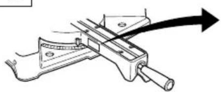
14. Cutting wide workpieces (Slide cutting)
Loosen the slide securing knob (see Fig. 2), grip the handle and slide the saw blade forward. Then press down on the handle and slide the saw blade back to cut the workpiece. This facilitates cutting of workpieces of up to 312 mm in width.
WARNING
Never put your hand on the side handle during the cutting operation because the saw blade comes close to the side handle when the motor head is lowered.
15. Miter cutting procedures
(1) Loosen the side handle and pull up the lever for angle stoppers. Then, adjust the turntable until the indicator aligns with desired setting on the miter scale (Fig. 17).
(2) Re-tighten the side handle to secure the turntable in the desired position.
(3) The miter scale indicates both the cutting angle on the angle scale and the gradient on the grade scale.
(4) The gradient, which is the ratio of the height to the base of the triangular section to be removed, may be used for setting the miter scale instead of the cutting angle, if desired.
(5) Therefore, to cut a workpiece at a grade of 2/10, set the indicator to position.
NOTE
○Positive stops are provided at the right and left of the 0^ center setting, at 15^ , 22.5^ , 30^ and 45^ settings. Check that the miter scale and the tip of the indicator are properly aligned.
Operation of the saw with the miter scale and indicator out of alignment, or with the side handle not properly tightened, will result in poor cutting precision.
16. Bevel cutting procedures CAUTION
○Ensure that the clamp lever is securely fixed when beveling.
Please do this if the length of the material being cut off is more than 25 mm long. Sometimes cutting cannot be accomplished because the saw blade will catch on the inside of the lower guard.
(1) Loosen the clamp lever and bevel the saw blade to the left or to the right. When tilting the motor head to the right pull the fixing pin towards the rear.
The clamp lever adopts a latchet system. When contacting the work bench and the main body, pull the clamp lever in the direction of the arrow mark as illustrated in Fig. 16, and change the direction of the clamp lever.
(2) Adjust the bevel angle to the desired setting while watching the bevel angle scale and indicator, then secure the clamp lever.
WARNING
When the workpiece is secured on the left or right side of the blade, the short cut-off portion will come to rest on the right or left side of the saw blade. Always turn the power off and let the saw blade stop completely before raising the handle from the workpiece.
If the handle is raised while the saw blade is still rotating, the cut-off piece may become jammed against the saw blade causing fragments to scatter about dangerously.
17. Compound cutting procedures
Compound cutting can be performed by following the instructions in 14 and 15 above. For maximum dimensions for compound cutting, refer to "SPECIFICATIONS" table.
CAUTION
○Always secure the workpiece with the right or left hand and cut it by sliding the round portion of the saw backwards with the left hand.
It is very dangerous to rotate the turntable to the left during compound cutting because the saw blade may come into contact with the hand that is securing the workpiece.
In case of compound cutting (angle + bevel) by left bevel, turn the sub-fence counterclockwise, and engage in the cutting operation.
18. Cutting long materials
When cutting long materials, use an auxiliary platform which is the same height as the holder (optional accessory) and base of the special auxiliary equipment.
Capacity: wooden material (W × H × L)
300 mm × 45 mm × 1300 mm, or
180 mm × 25 mm × 2000 mm
19. Installing the holders ... (Optional accessory)
The holders help keep longer workpieces stable and in place during the cutting operation.
(1) As indicated in Fig. 9, use a steel square for aligning the upper edge of the holders with the base surface. Loosen the 6 mm wing nut. Turn a height adjustment bolt 6 mm, and adjust the height of the holder.
(2) After adjustment, firmly tighten the wing nut and fasten the holder with the 6 mm knob bolt (optional accessory). If the length of Height Adjustment Bolt 6 mm is insufficient, spread a thin plate beneath. Make sure the end of Height Adjustment Bolt 6 mm does not protrude from the holder.
CAUTION
When transporting or carrying the tool, do not grasp the holder.
○There is the danger of the holder slipping out of the base. Grasp the handle instead of the holder.
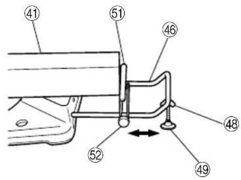
20. Stopper for precision cutting ... (Stopper and holder are optional accessory)
The stopper facilitates continuous precision cutting in lengths of 280 mm to 450 mm.
To install the stopper, attach it to the holder with the 6 mm knob bolt as shown in Fig. 10.
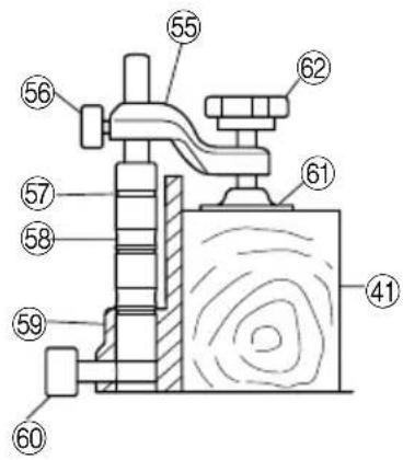
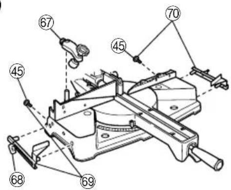
21. Confirmation for use Crown molding vise, Crown molding Stopper (L) and (R) (Optional accessory)
(1) Crown molding Stopper (L) and (R) (optional accessories) allow easier cuts of crown molding without tilting the saw blade. Install them in the base both-sides side to be shown in Fig. 18. After inserting tighten the 6 mm knob bolts to secure the Crown molding Stoppers.
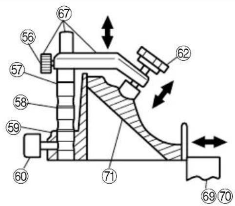
(2) The crown molding vise (B) (Optional accessory) can be mounted on either the left fence (Fence (B)) or the right fence (Fence (A)). It can unite with the slope of the crown molding and vice can be pressed down.
Then turn the upper knob, as necessary, to securely attach the crown molding in position. To raise or lower the vise assembly, first loosen the 6 mm knob bolt. As shown in Fig. 19 the vise shaft has three locking grooves into which the tip of the 6 mm wing bolt is designed to fit in order to lock the screw holder in the desired position.
Toensure that the tip of the 6 mm wing bolt is properly aligned with the desired locking groove on the vise shaft, simply align the upper surface of the fence to either of three v-grooves on the vise shaft surface or to the lower surface of the screw holder.
Therefore, the vise assembly can be attached in either of three positions to ensure proper height adjustment. After adjusting the height, firmly tighten the 6 mm wing bolt; then turn the upper knob, as necessary, to securely attach the crown molding in position (See Fig 19).
Position crown molding with its WALL CONTACT EDGE against the guide fence and its CEILING CONTACT EDGE against the Crown molding Stoppers as shown in Fig. 19. Adjust the Crown molding Stoppers according to the size of the crown molding. Tighten the 6 mm wing bolt to secure the Crown molding Stoppers. Refer to the lower table for the miter angle.
Use the sub fence (A) to secure the crown molding more firmly (See Fig. 11).
WARNING
○Always firmly clamp or vise to secure the crown molding to the fence; otherwise the crown molding might be thrust from the table and cause bodily harm. Do not bevel cutting. The main body or saw blade may contact the sub fence, resulting in an injury.
22. Groove cutting procedures
Grooves in the workpiece can be cut by adjusting the 8 mm depth adjustment bolt (Fig. 7).
(1) Loosen the 8 mm wing nut and turn the 8 mm depth adjustment bolt by hand.
(2) Adjust to the desired cutting depth by setting the distance between the saw blade and the surface of the base.
(3) The 8 mm wing nut must be properly tightened after the adjustment has been completed.
NOTE
When cutting a single groove at either end of the workpiece, remove the unneeded portion with a chisel.
MOUNTING AND DISMOUNTING SAW BLADE
WARNING
Toprevent an accident or personal injury, always turn off the trigger switch and disconnect the power plug from the receptacle before removing or installing a blade.
- Mounting the saw blade (Fig. 20, Fig. 21 and Fig. 22)
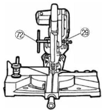
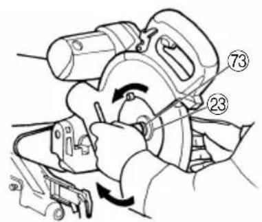
(1) Use the accessory 10 mm box wrench to loosen the 6 mm bolt fastening the spindle cover and then rotate the spindle cover.
(2) Press in spindle lock and loosen bolt with 10 mm box wrench.
Since the bolt is left-hand threaded, loosen by turning it to the right.
NOTE
○If the spindle lock cannot be easily pressed in to lock the spindle, turn the bolt with 10 mm box wrench while applying pressure on the spindle lock.
The saw blade spindle is locked when the spindle lock is pressed inward.
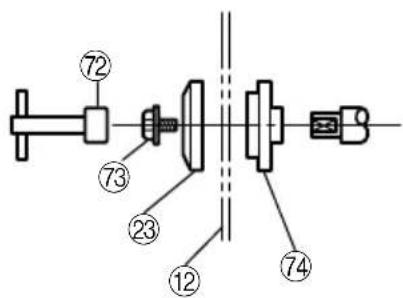
(3) Remove the bolt and washer (B).
(4) Lift the lower guard and mount the saw blade.
WARNING
When mounting the saw blade, confirm that the rotation indicator mark on the saw blade and the rotation direction of the gear case are properly matched.
(5) Thoroughly clean washer (B) and the bolt, and install them onto the saw blade spindle.
(6) Press in the spindle lock and tighten the bolt by turning it to the left by 10 mm box wrench.
(7) Rotate the spindle cover unit hook in spindle cover is in the original position. Then tighten the 6mm bolt.
CAUTION
○Confirm that the spindle lock has returned to the retract position after installing or removing the saw blade.
○Tighten the bolt so it does not come loose during operation.
○Confirm that the bolt has been properly tightened before the power tool is started.
○Confirm that the lower guard has closed position.
2. Dismounting the saw blade
Dismount the saw blade by reversing the mounting procedures described in paragraph 1 above.
The saw blade can easily be removed after lifting the lower guard.
CAUTION
☐Never attempt to install saw blades except 235 mm – 255 mm in diameter.
OVERLOAD PROTECTIVE DEVICE FOR POLY-V-BELT
The power of the motor is transmitted to the saw blade by a Poly-V-Belt. When the Poly-V-Belt becomes overloaded, this protective device reduces the input voltage and the motor is going to stall as result.
However if the over-load is relieved by operator, the machine recover the running gradually as before in short time.
In this case turn the switch off immediately and raise the handle to its initial position. Then turn the switch on and after running the tool for 20 seconds without a load for cooling of the motor. Then start the cutting operation.
The Poly-V-Belt or the motor will be damaged if the overload protective device turns off frequently.
CAUTION
When the overload protective device stops the motor, the motor will start by turning the switch on after turning it off. When turning the switch on, make sure that the saw blade is not halfway in the material.
MAINTENANCE AND INSPECTION
WARNING
To avoid an accident or personal injury, always confirm the trigger switch is turned OFF and that the power plug has been disconnected from the receptacle before performing any maintenance or inspection of this tool.
Report to qualified person as soon as possible, if you discover the fault of machine including guards or blade saw.
1. Inspecting the saw blade
Since use of a dull saw blade will degrade efficiency and cause possible motor malfunction, sharpen or replace the saw blade as soon as abrasion is noted.
To avoid excessive noise exposure, use the saw blades designed to reduce the emitted noise and maintain saw blade and machine.
2. Inspecting the mounting screws
Regularly inspect all mounting screws and ensure that they are properly tightened. Should any of the screws be loose, re-tighten them immediately. Failure to do so could result in serious hazard.
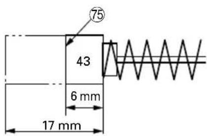
3. Inspecting the carbon brushes (Fig. 13)
The motor employs carbon brushes which are consumable parts. Since an excessively worn carbon brush can result in motor trouble, replace the carbon brushes with new ones having the same carbon brush No. shown in the figure when it becomes worn to or near the "wear limit". In addition, always keep carbon brushes clean and ensure that they slide freely within the brush holders.
4. Replacing a carbon brushes
Disassemble the brush cap with a slotted-head screwdriver. The carbon brushes can then be easily removed.
5. Maintenance of the motor
The motor unit winding is the very "heart" of the power tool. Exercise due care to ensure the winding does not become damaged and/or wet with oil or water.
6. Replacement of Poly-V-Belt
The power of the motor is transmitted to the saw blade by a Poly-V-Belt. When the Poly-V-Belt is broken or damaged, remove the belt cover by loosening the two 5 mm screws (see Fig. 2) and replace the damaged one with the new one.
When connecting the belt on pulleys, first connect 2 or 3 teeth of Poly-V-Belt to the grooves of the pulley (A) and pulley (B). Then turning the pulley (A) and pulley (B), connect all 10 teeth of the belt to the pulleys.
7. Lubrication
Lubricate the following sliding surfaces once a month to keep the power tool in good operating condition for a long time.
Use of machine oil is recommended.
Oil supply points:
* Rotary portion of hinge
* Rotary portion of sub fence
* Rotary portion of vise assembly
8. Cleaning
Periodically remove chips and other waste material from the surface of the power tool with a damp, soapy cloth. To avoid a malfunction of the motor, protect it from contact with oil or water.
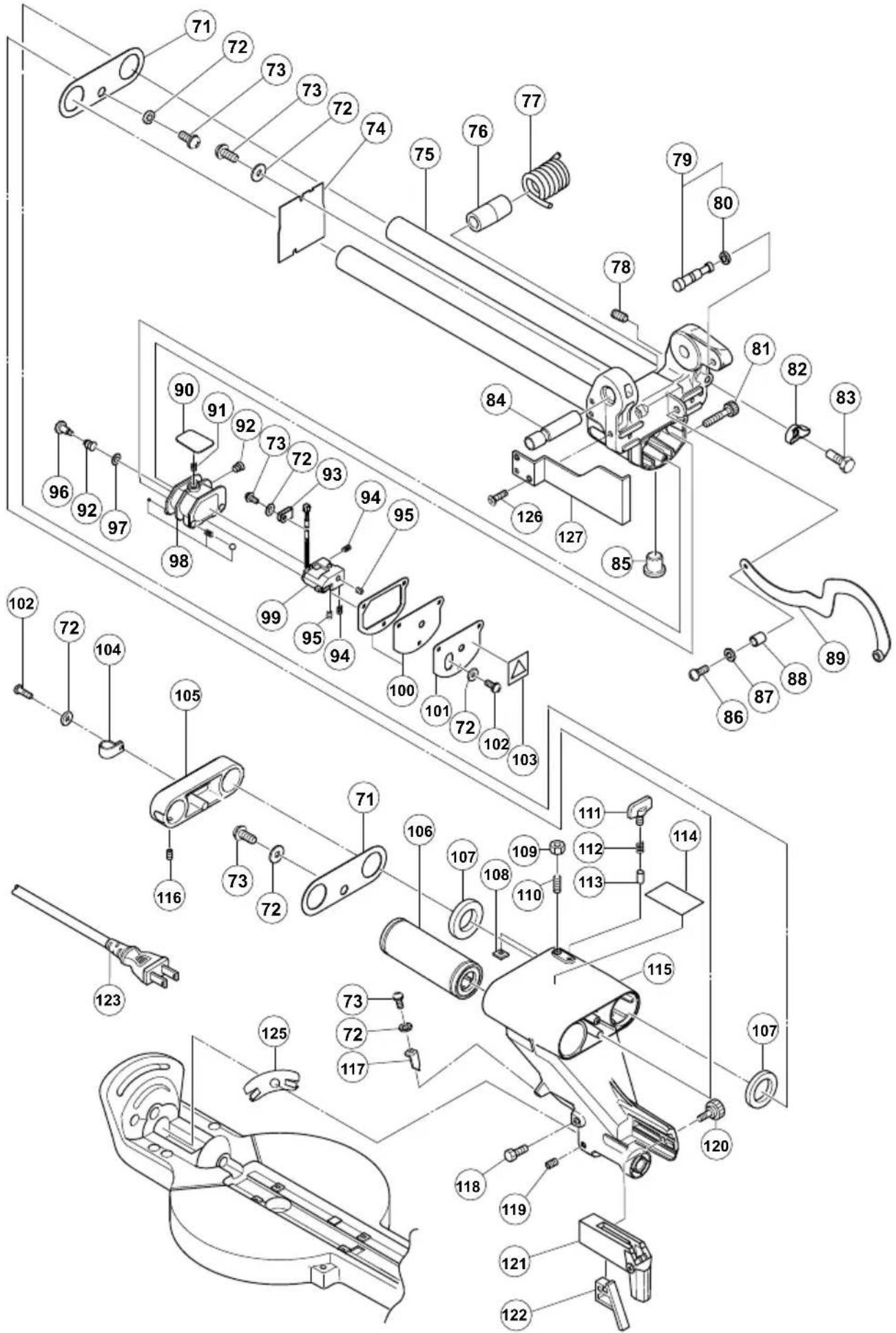
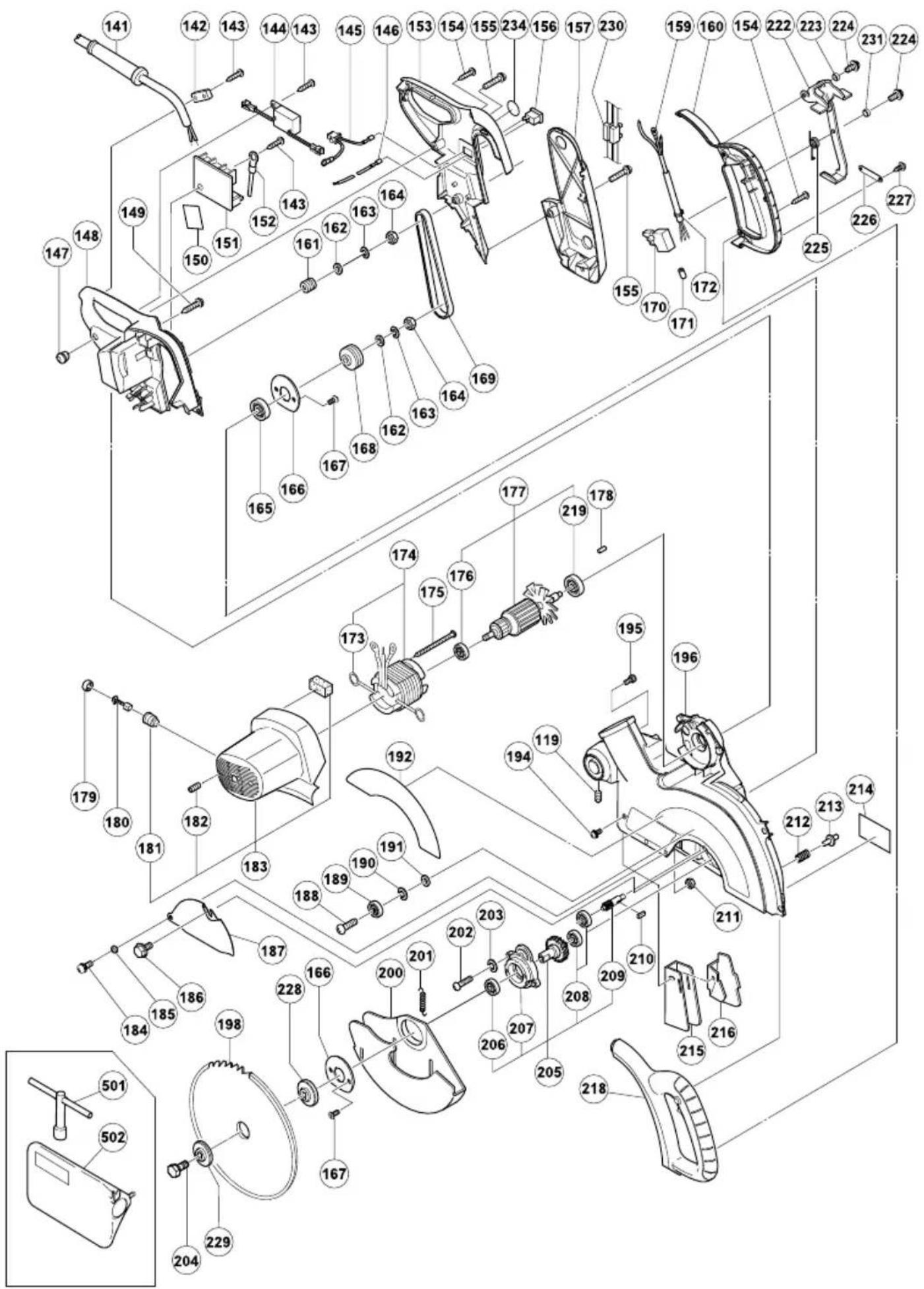
9. Service parts list
A : Item No.
B : Code No.
C : No. Used
D:Remarks
CAUTION
Repair, modification and inspection of HiKOKI Power Tools must be carried out by a HiKOKI Authorized Service Center.
Especially laser device should be maintained by the authorised agent by laser manufacturer.
Always assign the repair of laser device to HiKOKI Authorised Service Center.
This Parts List will be helpful if presented with the tool to the HiKOKI Authorized Service Center when requesting repair or other maintenance.
In the operation and maintenance of power tools, the safety regulations and standards prescribed in each country must be observed.
MODIFICATIONS
HiKOKI Power Tools are constantly being improved and modified to incorporate the latest technological advancements.
Accordingly, some parts (i.e. code numbers and/or design) may be changed without prior notice.
NOTE
Due to HiKOKI's continuing program of research and development the specifications herein are subject to change without prior notice.
IMPORTANT
Correct connection of the plug
The wires of the main lead are coloured in accordance with the following code:
Blue: -Neutral
Brown: -Live
As the colours of the wires in the main lead of this tool may not correspond with the coloured markings identifying the terminals in your plug proceed as follows: The wire coloured blue must be connected to the terminal marked with the letter N or coloured black. The wire coloured brown must be connected to the terminal marked with the letter L or coloured red. Neither code must be connected to the earth terminal.
NOTE
This requirement is provided according to BRITISH STANDARD 2769: 1984.
Therefore, the letter code and colour code may not be applicable to other markets except The United Kingdom.
Information concerning airborne noise and vibration
The measured values were determined according to EN61029.
The typical A-weighted sound pressure level: 93 dB(A)
The typical A-weighted sound power level: 106 dB (A)
Wear ear protection.
The typical weighted root mean square acceleration value does not exceed 2.5 m/s ^4 .
Information for power supply system to be used with electric tools provided with rated voltage 230 V\~
Switching operations of electric apparatus cause voltage fluctuations.
The operation of this electric tool under unfavorable mains conditions can have adverse effects to the operation of other electric apparatus.
With a mains impedance equal or less than 0.29 Ohms there will probably be no negative effects.
Usually, the maximum permissible mains impedance will not be exceeded when the branch to the power outlet is fed from a junction box with a service capacity of 25 ampere or higher.
In case of power failure, or when the power plug is pulled out, immediately return the switch to OFF position. This prevents an uncontrolled restart.
APPLICATIONS PRATIQUES
ATTENTION
(Materialaal stof: hout of aluminium)
300 mm × 45 mm × 1300 mm of
180 mm × 25 mm × 2000 mm
natural_image
Line drawing of a quill pen with inkwell (no text or symbols)| English | Nederlands | ||
| GUARANTEE CERTIFICATE1Model No.2Serial No.3Date of Purchase4Customer Name and Address5Dealer Name and Address(Please stamp dealer name and address) | GARANTIEBEWIJS1Modelnummer2Serienummer3Datum van aankoop4Naam en adres van de gebruiker5Naam en adres van de handelaar(Stempel a.u.b. naam en adres vande de handelaar) | ||
| Deutsch | GARANTIESCHEIN1Modell-Nr.2Serien-Nr.3Kaufdaturn4Name und Anschrift des Kunden5Name und Anschrift des Händlers(Bitte mit Namen und Anschrift des Handlers abstempeln) | Español | |
| CERTIFICADO DE GARANTIA1Número de modelo2Número de serie3Fecha de adquisición4Nombre y dirección del cliente5Nombre y dirección del distribudor(Se ruega poner el sellú del distribudor con su nombre y dirección) | |||
| Français Português | |||
| CERTIFICAT DE GARANTIE1No. de modèle2No. de série3Date d'achat4Nom et adresse du client5Nom et adresse du revendeur(Cachet portant le nom et l'adresse du revendeur) | CERTIFICADO DE GARANTIA1Número do modelo2Número do série3Data de compra4Nome e morada do cliente5Nome e morada do distribuidor(Por favor, carímbe o nome e morada do distribuidor) | ||
| Italiano Ελληνικά | |||
| CERTIFICATO DI GARANZIA1Modello2N° di serie3Data di acquisto4Nome e indirizzo dell'acquirente5Nome e indirizzo del rivenditore(Si prega di apporre il timbro con questi dati) | ΠΙΣΤΟΠΟΙΗΤΙΚΟ ΕΓΓΥΗΣΗΣ1Ap. Movτέλου2Αύξων Ap.3Ημερομηνία αγοράς4Όνομα και διεύθυνση πελάτη5Όνομα και διεύθυνση μεταπωλητή(Παρακαλούμε να χρησιμοποιηθεί σφραγίδα) | ||
HiKOKI
| 1 | |
| 2 | |
| 3 | |
| 4 | |
| 5 |
natural_image
Line drawing of a quill pen with inkwell (no text or symbols)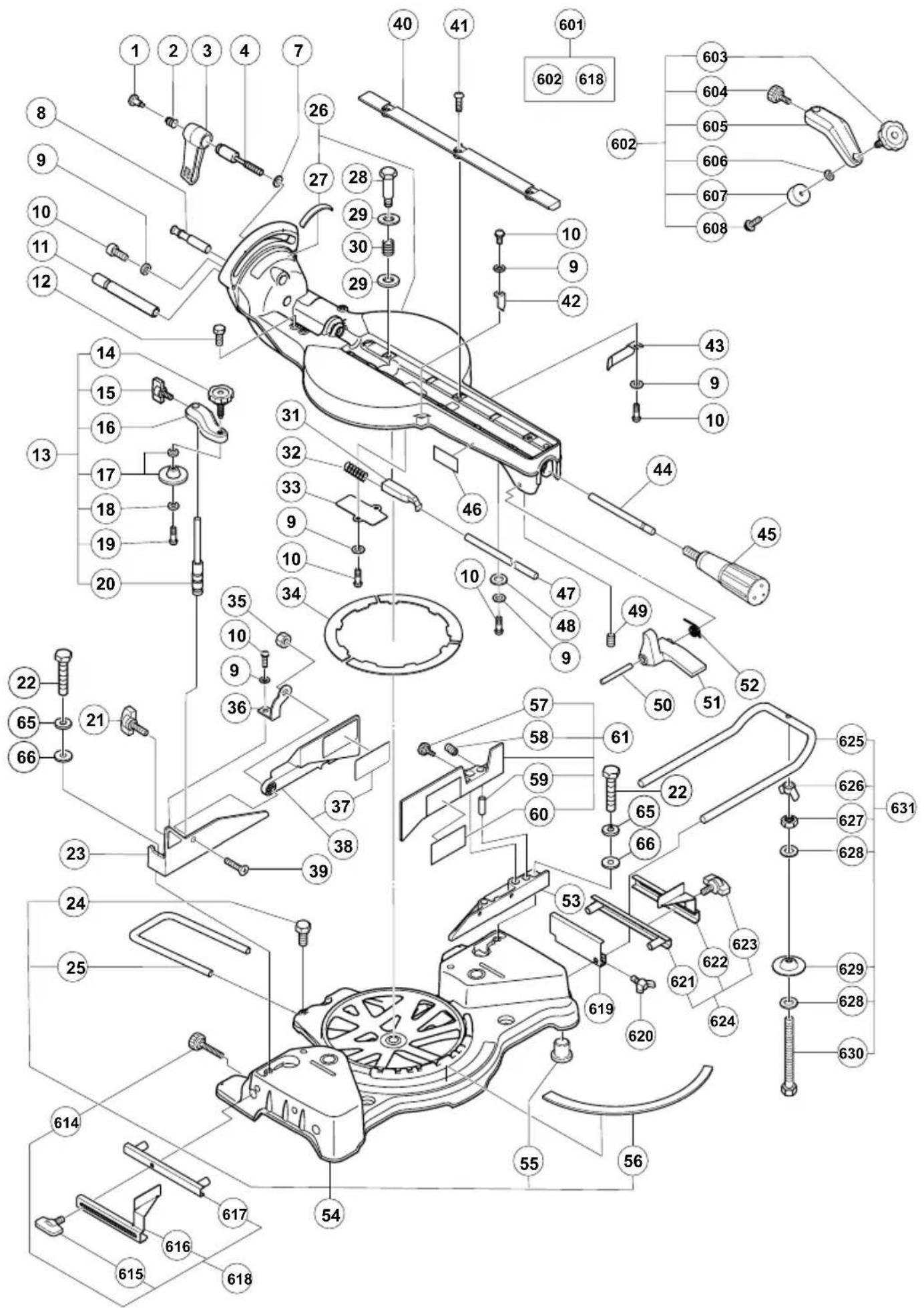
C10FSH
C10FSH
| A | B | C | D |
| 1 305-180 1 | |||
| 2 305-179 1 | |||
| 3 312-488 1 | |||
| 4 329-409 1 M10 | |||
| 7 965-077 1 | |||
| 8 321-330 1 | |||
| 9 949-429 8 M4 | |||
| 10 949-215 8 M4 × 8 | |||
| 11 320-141 1 | |||
| 12 | 303-409 | 2 | M8 × 25 |
| 13 321-370 1 "14-20" | |||
| 14 308-396 1 M10 | |||
| 15 | 307-947 | 1 | M6 × 12 |
| 16 ———— 1 | |||
| 17 319-974 1 | |||
| 18 996-722 1 | |||
| 19 | 996-247 | 1 | M5 × 12 |
| 20 321-371 1 | |||
| 21 | 302-459 | 1 | M6 × 17 |
| 22 | 949-678 | 4 | M8 × 35 |
| 23 321-346 1 | |||
| 24 | 949-610 | 1 | M6 × 10 |
| 25 998-844 1 | |||
| 26 330-768 1 9, 10, 27-34, 40, 41, 43, 44, 47-52, 54 | |||
| 27 321-343 1 | |||
| 28 312-480 1 | |||
| 29 949-437 2 M12 | |||
| 30 312-481 1 | |||
| 31 321-335 1 | |||
| 32 321-417 1 | |||
| 33 321-336 1 | |||
| 34 998-811 3 | |||
| 35 311-144 1 M6 | |||
| 36 321-331 1 | |||
| 37 ———— 1 | |||
| 38 321-385 1 "37" | |||
| 39 | 949-342 | 1 | M6 × 25 |
| 40 319-549 2 | |||
| 41 | 949-256 | 6 | M6 × 16 |
| 42 321-329 1 | |||
| 43 321-342 1 | |||
| 44 329-416 1 | |||
| 45 322-283 1 | |||
| 46 ———— 1 | |||
| 47 329-415 1 | |||
| 48 875-249 2 | |||
| 49 987-860 1 M6 × 6 | |||
| 50 321-339 1 | |||
| 51 321-338 1 | |||
| 52 321-340 1 | |||
| 53 321-345 1 | |||
| 54 330-768 1 9, 10, 26-34, 40, 41, 43, 44, 47-52 | |||
| 55 321-672 4 | |||
| 56 315-210 1 | |||
| 57 | 960-017 | 1 | M6 × 32 |
| 58 987-860 2 M6 × 6 | |||
| 59 321-552 2 | |||
| 60 ———— 1 | |||
| 61 322-617 1 "57-60" | |||
| 65 949-457 4 M8 | |||
| 66 949-433 4 M8 | |||
| 71 996-227 2 | |||
| A | B | C | D |
| 72 949-429 11 M4 | |||
| 73 949-215 6 M4 × 8 | |||
| 74 321-349 1 "89" | |||
| 75 332-814 1 "105" | |||
| 76 996-276 1 | |||
| 77 321-332 1 | |||
| 78 | 961-554 | 1 | M8 × 10 |
| 79 302-518 1 "80" | |||
| 80 984-528 1 P-6 | |||
| 81 319-270 1 | |||
| 82 949-312 1 M8 | |||
| 83 | 949-633 | 1 | M8 × 50 |
| 84 320-141 1 | |||
| 85 312-672 1 | |||
| 86 | 949-237 | 1 | M5 × 12 |
| 87 | 949-454 | 1 | M4 × 12 |
| 88 998-980 1 | |||
| 89 322-199 1 | |||
| 90 319-268 1 | |||
| 91 319-267 1 | |||
| 92 305-179 2 | |||
| 93 980-523 1 | |||
| 94 319-267 2 | |||
| 95 319-541 2 M5 × 6 | |||
| 96 305-180 1 | |||
| 97 962-614 1 T0.5 | |||
| 98 319-269 1 | |||
| 99 329-863 1 | |||
| 100 319-271 1 | |||
| 101 319-272 1 | |||
| 102 | 949-217 | 5 | M4 × 12 |
| 103 ———— 1 | |||
| 104 948-614 1 | |||
| 105 331-419 1 | |||
| 106 321-347 1 | |||
| 107 996-226 2 | |||
| 108 996-223 2 | |||
| 109 949-568 2 M8 | |||
| 110 | 974-500 | 2 | M8 × 16 |
| 111 | 302-459 | 1 | M6 × 17 |
| 112 947-859 1 | |||
| 113 963-174 1 | |||
| 114 ———— 1 | |||
| 115 321-375 1 | |||
| 116 | 961-554 | 2 | M8 × 10 |
| 117 321-329 2 | |||
| 118 | 303-409 | 1 | M8 × 25 |
| 119 | 307-956 | 2 | M5 × 10 |
| 120 | 302-503 | 1 | M6 × 22 |
| 121 321-333 1 | |||
| 122 331-845 1 | |||
| 123 ———— 1 | |||
| 125 322-210 1 | |||
| 126 | 949-332 | 2 | M5 × 12 |
| 127 322-206 1 | |||
| 141 938-051 1 | |||
| 142 937-631 1 | |||
| 143 | 984-750 | 4 | D4 × 16 |
| 144 1 321-378 1 110V-120V | |||
| 144 2 322-383 1 220V-240V | |||
| 145 1 322-384 1 | |||
| 145 2 322-450 1 "GBR (110V)" | |||
| 146 321-377 1 | |||
| 147 319-349 1 | |||
C10FSH
| A | B | C | D |
| 148 | 321-550 | 1 | |
| 149 | 305-558 | 3 | D5 × 25 |
| 150 | 321-355 | 1 | |
| 151 | 1 321-354 | 1 | 110V-120V |
| 151 | 2 322-200 | 1 | 220V-240V |
| 152 | 930-804 | 1 M4.0 | |
| 153 | 321-380 | 1 | |
| 154 | 301-653 | 6 | D4 × 20 |
| 155 | 880-734 | 4 | M5 × 25 |
| 156 | 319-503 | 1 | |
| 157 | 321-383 | 1 | |
| 159 | 980-063 | 1 | |
| 160 | 322-884 | 1 "218" | |
| 161 | 321-356 | 1 | |
| 162 | 949-426 | 2 M8 | |
| 163 | 978-559 | 2 | |
| 164 | 949-558 | 2 | |
| 165 | 620-1VV | 1 6201VVCMPS2L | |
| 166 | 307-731 | 2 | |
| 167 | 949-322 | 4 | M4 × 10 |
| 168 | 321-357 | 1 | |
| 169 | 332-810 | 1 | |
| 170 | 998-868 | 1 | |
| 171 | 981-373 | 4 | |
| 172 | 322-207 | 1 "159, 171" | |
| 173 | 930-703 | 2 | |
| 174 | 1 340-779C | 1 110V "173" | |
| 174 | 2 340-779F | 1 230V-240V "173" | |
| 175 | 953-174 | 2 D5 × 55 | |
| 176 | 321-399 | 1 608VVC2NS7L | |
| 177 | 1 360-898U | 1 110V-120V "176, 219" | |
| 177 | 2 360-898E | 1 230V | |
| 178 | 946-362 | 1 | |
| 179 | 945-161 | 2 | |
| 180 | 999-043 | 2 | |
| 181 | 960-685 | 2 | |
| 182 | 938-477 | 2 M5 × 8 | |
| 183 | 322-208 | 1 "181, 182" | |
| 184 | 996-247 | 1 | M5 × 12 |
| 185 | 998-980 | 1 | |
| 186 | 996-577 | 1 | M6 × 12 |
| 187 | 318-958 | 1 | |
| 188 | 949-258 | 1 | M6 × 20 |
| 189 | 606-ZZM | 1 606ZZC2PS2L | |
| 190 | 949-455 | 1 M6 | |
| 191 | 949-425 | 1 M6 | |
| 192 | ——— | 1 | |
| 194 | 304-043 | 1 | M4 × 10 |
| 195 | 977-839 | 1 | M5 × 10 |
| 196 | 321-384 | 1 | |
| 198 | 322-443 | 1 255MM-D30 HOLE-NT40 | |
| 200 | 322-452 | 1 | |
| 201 | 322-453 | 1 | |
| 202 | 949-241 | 2 | M5 × 20 |
| 203 | 949-454 | 2 M5 | |
| 204 | 998-335 | 1 | M7 × 17.5 |
| 205 | 308-787 | 1 "206-209" | |
| 206 | 600-3DD | 1 6003DDCMPS2S | |
| 207 | 308-788 | 1 | |
| 208 | 608-VVM | 2 608VVC2PS2L | |
| 209 | ——— | 1 | |
| 210 | 931-008 | 1 | 4 × 4 × 12 |
| A | B | C | D |
| 211 949-555 1 M5 | |||
| 212 988-821 1 | |||
| 213 307-732 1 | |||
| 214 ———— 1 | |||
| 215 322-454 1 | |||
| 216 312-492 1 | |||
| 218 322-884 1 "160" | |||
| 219 321-398 1 6201VVCMNS7S | |||
| 222 322-456 1 | |||
| 223 302-757 2 | |||
| 224 | 935-196 | 3 | M4 × 12 |
| 225 322-457 1 | |||
| 226 322-458 1 | |||
| 227 | 306-371 | 2 | D3 × 10 |
| 228 322-459 1 | |||
| 229 318-962 1 | |||
| 230 958-308Z 1 | |||
| 231 305-171 1 | |||
| 234 320-104 1 | |||
| 501 940-543 1 10MM | |||
| 502 998-845 1 | |||
| 601 321-434 1 "602, 618" | |||
| 602 321-388 1 "603-608" | |||
| 603 | 321-551 | 1 | M10 × 54 |
| 604 | 998-836 | 1 | M6 × 11 |
| 605 ———— 1 | |||
| 606 306-985 1 | |||
| 607 964-851 1 | |||
| 608 | 304-043 | 1 | M4 × 10 |
| 614 | 960-017 | 1 | M6 × 32 |
| 615 | 301-806 | 1 | M6 × 15 |
| 616 ———— 1 | |||
| 617 321-390 1 | |||
| 618 321-374 1 "614-617" | |||
| 619 974-561 1 | |||
| 620 | 949-404 | 1 | M6 × 20 |
| 621 321-390 1 | |||
| 622 ———— 1 | |||
| 623 | 301-806 | 1 | M6 × 15 |
| 624 321-373 1 "614, 621-623" | |||
| 625 321-549 2 | |||
| 626 949-313 2 M6 | |||
| 627 949-556 2 M6 | |||
| 628 967-329 4 | |||
| 629 996-261 2 | |||
| 630 | 996-283 | 2 | M6 × 65 |
| 631 321-553 1 "614, 619, 620, 625-630" | |||
| 634 322-444 1 225MM-D30 HOLE-NT72 | |||
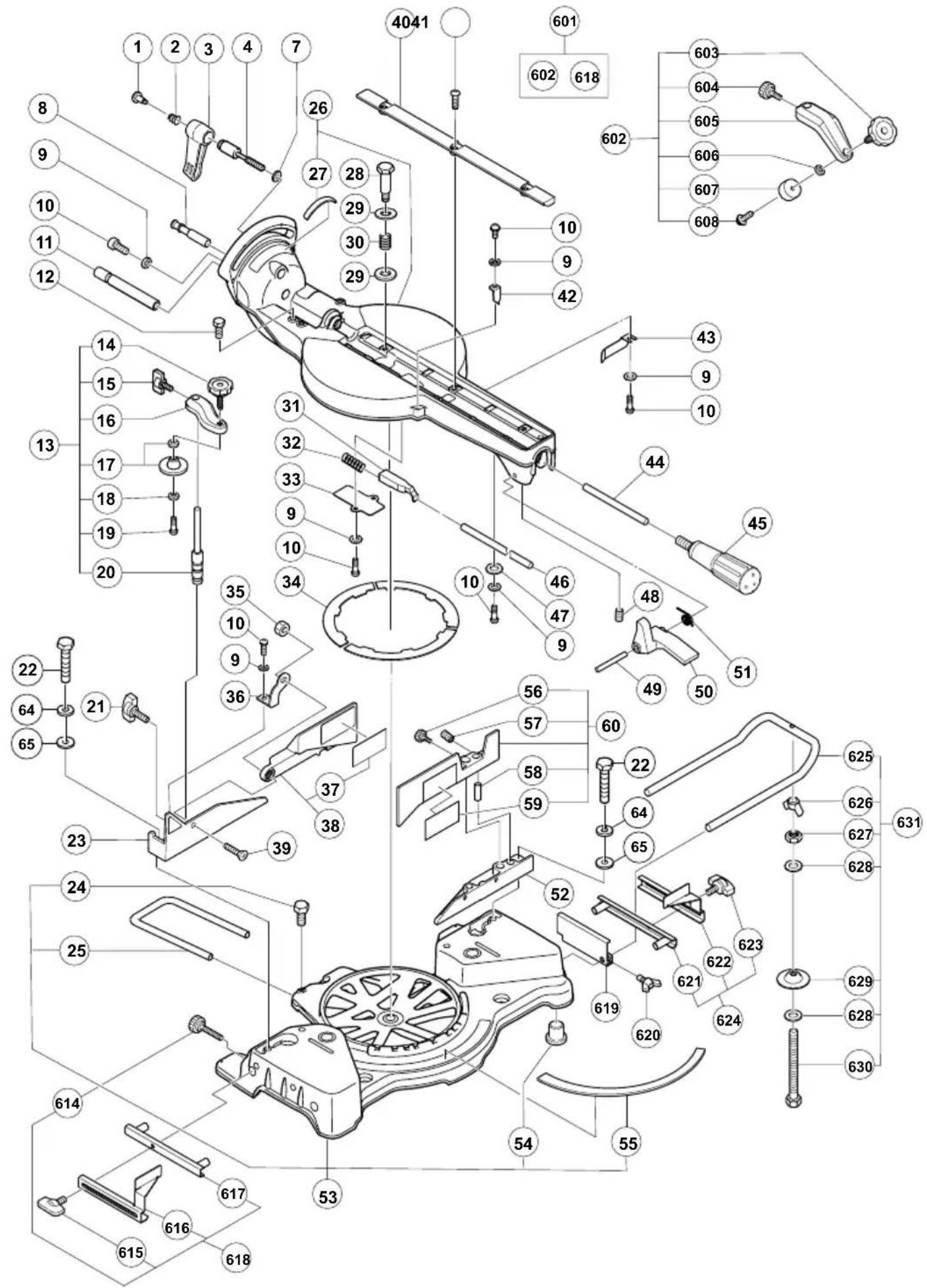
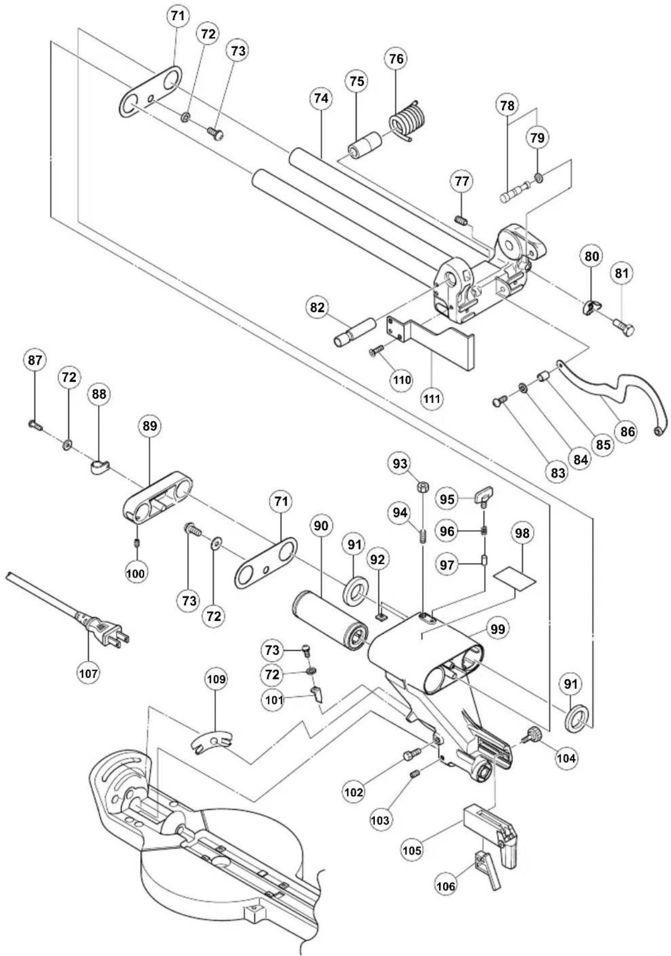
C10FSB
C10FSB
| A | B | C | D |
| 1 305-180 1 | |||
| 2 305-179 1 | |||
| 3 312-488 1 | |||
| 4 329-409 1 M10 | |||
| 7 965-077 1 | |||
| 8 321-330 1 | |||
| 9 949-429 8 M4 | |||
| 10 949-215 8 M4 × 8 | |||
| 11 320-141 1 | |||
| 12 | 303-409 | 2 | M8 × 25 |
| 13 321-370 1 "14-20" | |||
| 14 308-396 1 M10 | |||
| 15 | 307-947 | 1 | M6 × 12 |
| 16 ———— 1 | |||
| 17 319-974 1 | |||
| 18 996-722 1 | |||
| 19 | 996-247 | 1 | M5 × 12 |
| 20 321-371 1 | |||
| 21 | 302-459 | 1 | M6 × 17 |
| 22 | 949-678 | 4 | M8 × 35 |
| 23 321-346 1 | |||
| 24 | 949-610 | 1 | M6 × 10 |
| 25 998-844 1 | |||
| 26 330-768 1 9, 10, 27-34, 40, 41, 43, 44, 46-51, 53 | |||
| 27 321-343 1 | |||
| 28 312-480 1 | |||
| 29 949-437 2 M12 | |||
| 30 312-481 1 | |||
| 31 322-280 1 | |||
| 32 321-417 1 | |||
| 33 321-336 1 | |||
| 34 324-400 3 | |||
| 35 311-144 1 M6 | |||
| 36 321-331 1 | |||
| 37 ———— 1 | |||
| 38 321-385 1 "37" | |||
| 39 | 949-342 | 1 | M6 × 25 |
| 40 998-818 2 | |||
| 41 | 949-256 | 6 | M6 × 20 |
| 42 321-329 1 | |||
| 43 321-342 1 | |||
| 44 329-416 1 | |||
| 45 322-283 1 | |||
| 46 329-415 1 | |||
| 47 875-249 2 | |||
| 48 987-860 1 M6 × 6 | |||
| 49 321-339 1 | |||
| 50 321-338 1 | |||
| 51 321-340 1 | |||
| 52 321-345 1 | |||
| 53 330-768 1 9, 10, 26-34, 40, 41, 43, 44, 46-51 | |||
| 54 321-672 4 | |||
| 55 315-210 1 | |||
| 56 | 960-017 | 1 | M6 × 32 |
| 57 987-860 2 M6 × 6 | |||
| 58 321-552 2 | |||
| 59 ———— 1 | |||
| 60 322-617 1 "56-59" | |||
| 64 949-457 4 M8 | |||
| 65 949-433 4 M8 | |||
| 71 996-227 2 | |||
| 72 949-429 5 M4 | |||
| A | B | C | D |
| 73 949-215 4 M4 × 8 | |||
| 74 332-817 1 "89" | |||
| 75 996-276 1 | |||
| 76 321-332 1 | |||
| 77 | 961-554 | 1 | M8 × 10 |
| 78 302-518 1 "79" | |||
| 79 984-528 1 P-6 | |||
| 80 949-312 1 M8 | |||
| 81 | 949-633 | 1 | M8 × 50 |
| 82 320-141 1 | |||
| 83 | 949-237 | 1 | M5 × 12 |
| 84 | 949-454 | 1 | M4 × 12 |
| 85 998-980 1 | |||
| 86 322-199 1 | |||
| 87 | 949-217 | 1 | M4 × 12 |
| 88 948-614 1 | |||
| 89 331-419 1 | |||
| 90 321-347 1 | |||
| 91 996-226 2 | |||
| 92 996-223 2 | |||
| 93 949-568 2 M8 | |||
| 94 | 974-500 | 2 | M8 × 16 |
| 95 | 302-459 | 1 | M6 × 17 |
| 96 947-859 1 | |||
| 97 963-174 1 | |||
| 98 ———— 1 | |||
| 99 321-375 1 | |||
| 100 | 961-554 | 2 | M8 × 10 |
| 101 321-329 2 | |||
| 102 | 303-409 | 1 | M8 × 25 |
| 103 | 307-956 | 2 | M6 × 10 |
| 104 | 302-503 | 1 | M6 × 22 |
| 105 321-333 1 | |||
| 106 331-845 1 | |||
| 107 ———— 1 | |||
| 109 322-210 1 | |||
| 110 | 949-332 | 1 | M5 × 12 |
| 111 322-206 1 | |||
| 121 938-051 1 | |||
| 122 937-631 1 | |||
| 123 | 984-750 | 3 | D4 × 16 |
| 124 321-392 1 | |||
| 125 | 305-558 | 3 | D5 × 25 |
| 126 321-355 1 | |||
| 127 1 321-354 1 110V-120V | |||
| 127 2 322-200 1 220V-240V | |||
| 128 930-804 1 M4.0 | |||
| 129 321-393 1 | |||
| 130 | 301-653 | 6 | D4 × 20 |
| 131 | 880-734 | 4 | M5 × 25 |
| 132 321-383 1 | |||
| 134 980-063 1 | |||
| 135 322-884 1 "195" | |||
| 136 321-356 1 | |||
| 137 949-426 2 M8 | |||
| 138 978-559 2 | |||
| 139 949-558 2 M8 | |||
| 140 620-1VV 1 6201VVCMPS2L | |||
| 141 307-731 2 | |||
| 142 | 949-322 | 2 | M4 × 10 |
| 143 321-357 1 | |||
| 144 332-810 1 | |||
| 145 998-868 1 | |||
| 146 981-373 4 | |||
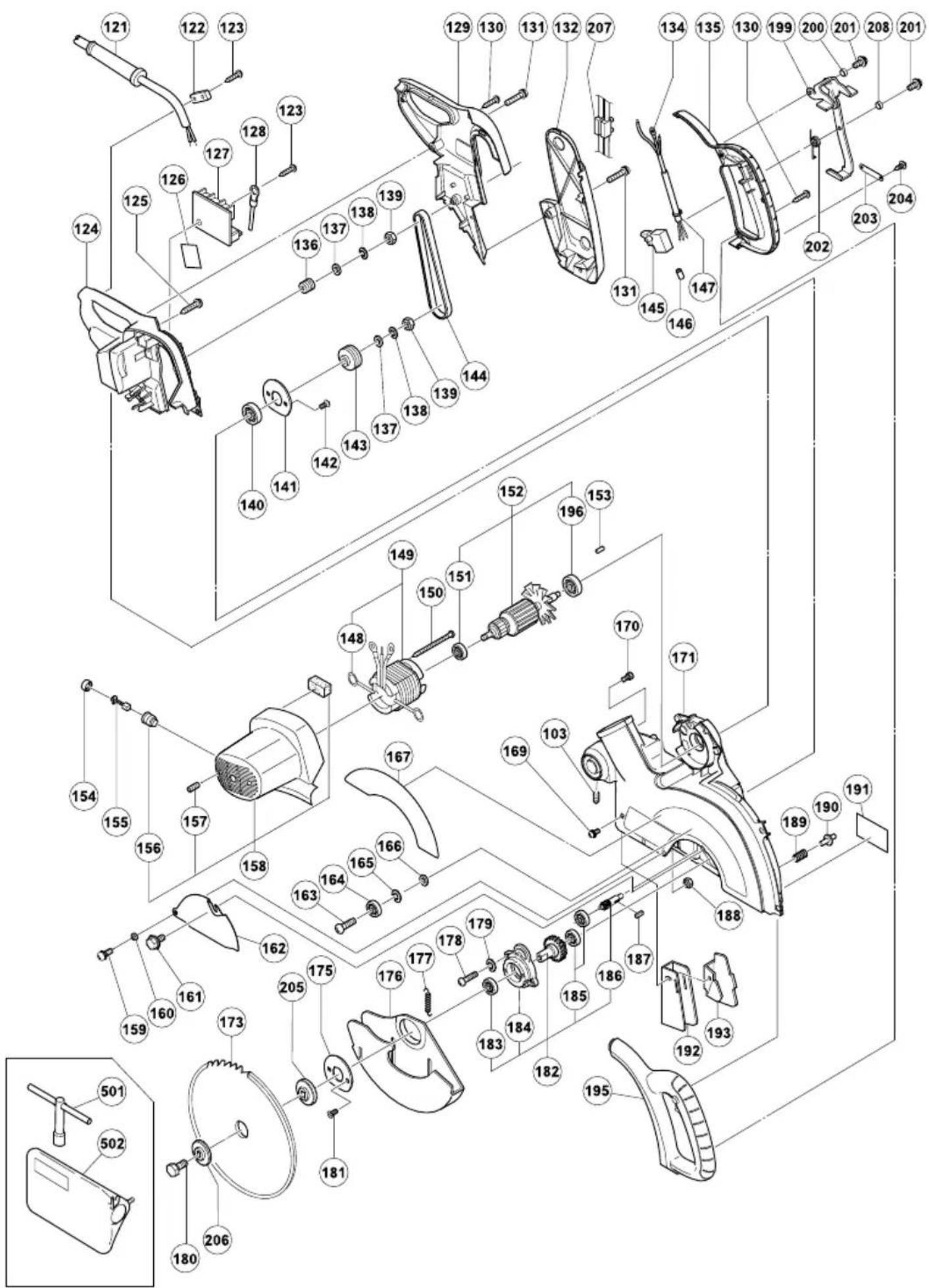
C10FSB
| A | B | C | D |
| 147 | 322-207 1 "134, 146" | ||
| 148 | 930-703 2 | ||
| 149 | 1 340-779C 1 110V "148" | ||
| 149 | 2 340-779F 1 230V-240V "148" | ||
| 150 | 953-174 | 2 D5 × 55 | |
| 151 | 321-399 1 608VVC2NS7L | ||
| 152 | 1 360-898U 1 110V-120V "151, 196" | ||
| 152 | 2 360-898E 1 230V "151, 196" | ||
| 153 | 946-362 1 | ||
| 154 | 945-161 2 | ||
| 155 | 999-043 2 | ||
| 156 | 960-685 2 | ||
| 157 | 938-477 2 M5 × 8 | ||
| 158 | 322-208 1 "156, 157" | ||
| 159 | 996-247 | 1 M5 × 12 | |
| 160 | 998-980 1 | ||
| 161 | 996-577 | 1 M6 × 12 | |
| 162 | 318-958 1 | ||
| 163 | 949-258 | 1 M6 × 20 | |
| 164 | 606-ZZM 1 606ZZC2PS2L | ||
| 165 | 949-455 1 M6 | ||
| 166 | 949-425 1 M6 | ||
| 167 | ——— 1 | ||
| 169 | 304-043 | 1 M4 × 10 | |
| 170 | 977-839 | 1 M5 × 10 | |
| 171 | 321-384 1 | ||
| 173 | 322-443 1 255MM-D30 HOLE-NT40 | ||
| 175 | 307-731 1 | ||
| 176 | 322-452 1 | ||
| 177 | 322-453 1 | ||
| 178 | 949-241 | 2 M5 × 20 | |
| 179 | 949-454 2 M5 | ||
| 180 | 998-335 | 1 M7 × 17.5 | |
| 181 | 949-322 | 2 M4 × 10 | |
| 182 | 308-787 1 "183-186" | ||
| 183 | 600-3DD 1 6003DDCMPS2S | ||
| 184 | 308-788 1 | ||
| 185 | 608-VVM 2 608VVC2PS2L | ||
| 186 | ——— 1 | ||
| 187 | 931-008 | 1 4 × 4 × 12 | |
| 188 | 949-555 1 M5 | ||
| 189 | 988-821 1 | ||
| 190 | 307-732 1 | ||
| 191 | ——— 1 | ||
| 192 | 322-454 1 | ||
| 193 | 312-492 1 | ||
| 195 | 322-884 1 "135" | ||
| 196 | 321-398 1 6201VVCMNS7S | ||
| 199 | 322-456 1 | ||
| 200 | 302-757 2 | ||
| 201 | 935-196 | 3 M4 × 12 | |
| 202 | 322-457 1 | ||
| 203 | 322-458 1 | ||
| 204 | 306-371 | 2 D3 × 10 | |
| 205 | 322-459 1 | ||
| 206 | 318-962 1 | ||
| 207 | 958-308Z 1 | ||
| 208 | 305-171 1 | ||
| 501 | 940-543 1 10MM | ||
| 502 | 998-845 1 | ||
| 601 | 321-434 1 "602, 618" | ||
| 602 | 321-388 1 "603-608" | ||
| 603 | 321-551 | 1 M10 × 54 | |
| 604 | 998-836 | 1 M6 × 11 |
| A | B | C | D |
| 605 | 1 | ||
| 606 | 306-985 1 | ||
| 607 | 964-851 1 | ||
| 608 | 304-043 | 1 | M4 × 10 |
| 614 | 960-017 | 1 | M6 × 32 |
| 615 | 301-806 | 1 | M6 × 15 |
| 616 | 1 | ||
| 617 | 321-390 1 | ||
| 618 | 321-374 1 "614-617" | ||
| 619 | 974-561 1 | ||
| 620 | 949-404 | 1 | M6 × 20 |
| 621 | 321-390 1 | ||
| 622 | 1 | ||
| 623 | 301-806 | 1 | M6 × 15 |
| 624 | 321-373 1 "614, 621-623" | ||
| 625 | 321-549 2 | ||
| 626 | 949-313 2 M6 | ||
| 627 | 949-556 2 M6 | ||
| 628 | 967-329 4 | ||
| 629 | 996-261 2 | ||
| 630 | 996-283 | 2 | M6 × 65 |
| 631 | 321-553 1 "614, 619, 620, 625-630" | ||
| 634 | 322-444 1 225MM-D30 HOLE-NT72 |

natural_image
Line drawing of a quill pen with inkwell (no text or symbols)Siemensring 34, 47877 willich, Germany
Tel: +49 2154 49930
Fax: +49 2154 499350
URL: http://www.hikoki-powertools.de
Hikoki Power Tools Netherlands B.V.
Brabanthaven 11, 3433 PJ Nieuwegein, The Netherlands
Tel: +31 30 6084040
Fax: +31 30 6067266
URL: http://www.hikoki-powertools.nl
Hikoki Power Tools (U.K.) Ltd.
Precedent Drive, Rooksley, Milton Keynes, MK 13, 8PJ, United Kingdom
Tel: +44 1908 660663
Fax: +44 1908 606642
URL: http://www.hikoki-powertools.uk
Hikoki Power Tools France S.A.S.
Hikoki Power Tools Belgium N.V./S.A.
Koningin Astridlaan 51, B-1780 Wemmel, Belgium
Tel: +32 2 460 1720
Fax: +32 2 460 2542
URL http://www.hikoki-powertools.be
Hikoki Power Tools Italia S.p.A
Via Piave 35, 36077, Altavilla Vicentina (VI), Italy
Tel: +39 0444 548111
Fax: +39 0444 548110
URL: http://www.hikoki-powertools.it
Hikoki Power Tools Ibérica, S.A.
C/ Puigbarral, 26-28, Pol. Ind. Can Petit, 08227 Terrassa
(Barcelona), Spain
Tel: +34 93 735 6722
Fax: +34 93 735 7442
URL: http://www.hikoki-powertools.es

- PRECAUTIONS ON USING SLIDE COMPOUND MITER SAW
- STANDARD ACCESSORIES
- OPTIONAL ACCESSORIES (SOLD SEPARATELY)
- APPLICATION
- UNPACKING
- PRIOR TO OPERATION
- Power source
- Power switch
- Extention cord
- When the power tool is prepared for shipping, its main parts are secured by a locking pin
- Attach the dust bag to the main unit (Fig. 1)
- Installation
- ADJUSTING THE POWER TOOL PRIOR TO USE
- CAUTION
- Check to see that the lower guard operates smoothly CAUTION
- Checking the saw blade lower limit position (Fig. 7)
- PRACTICAL APPLICATIONS
- Tightly secure the material by vise assembly to be cut so that it does not move during cutting
- Switch operation
- Base holder adjustment (Fig. 3)
- Cutting a groove on the guard
- Adjusting the guard (Fig. 6)
- Using the Vise Assembly (Standard accessory) (Fig. 12)
- WARNING
- Positioning the table insert (Fig. 1)
- Confirmation for use of sub fence
- Confirmation for use of sub fence (A) (Fig. 11)
- Using an ink line
- CAUTION (Fig. 13)
- NOTE
- Cutting operation
- Cutting narrow workpieces (Press cutting)
- Cutting wide workpieces (Slide cutting)
- Miter cutting procedures
- Bevel cutting procedures CAUTION
- Compound cutting procedures
- Cutting long materials
- Installing the holders ... (Optional accessory)
- Stopper for precision cutting ... (Stopper and holder are optional accessory)
- Confirmation for use Crown molding vise, Crown molding Stopper (L) and (R) (Optional accessory)
- Groove cutting procedures
- MOUNTING AND DISMOUNTING SAW BLADE
- Dismounting the saw blade
- OVERLOAD PROTECTIVE DEVICE FOR POLY-V-BELT
- MAINTENANCE AND INSPECTION
- Inspecting the saw blade
- Inspecting the mounting screws
- Inspecting the carbon brushes (Fig. 13)
- Replacing a carbon brushes
- Maintenance of the motor
- Replacement of Poly-V-Belt
- Lubrication
- Cleaning
- Service parts list
- MODIFICATIONS
- IMPORTANT
- Information concerning airborne noise and vibration
- Information for power supply system to be used with electric tools provided with rated voltage 230 V\~
- APPLICATIONS PRATIQUES
- ATTENTION
- Hikoki Power Tools Netherlands B.V.
- Hikoki Power Tools (U.K.) Ltd.
- Hikoki Power Tools France S.A.S.
- Hikoki Power Tools Belgium N.V./S.A.
- Hikoki Power Tools Italia S.p.A
- Hikoki Power Tools Ibérica, S.A.
Brand : HiKOKI
Model : C10FSB
Category : Saw