
WM10DBL - Screwdriver HiKOKI - Free user manual and instructions
Find the device manual for free WM10DBL HiKOKI in PDF.
| Product type | Cordless electronic impact screwdriver |
| Brand | HiKOKI |
| Model | WM10DBL |
| Battery type | Lithium-ion 10.8 V (BCL1015 1.5 Ah or BCL1030M 3.0 Ah) |
| Dimensions (with BCL1015) | 139 mm × 216 mm × 29 mm |
| Dimensions (with BCL1030M) | 139 mm × 233 mm × 29 mm |
| Weight (with BCL1015) | 1.0 kg |
| Weight (with BCL1030M) | 1.2 kg |
| No-load speed (depending on mode) | 0 - 2200 min⁻¹ |
| Maximum torque | 20 N·m |
| Number of operating modes | 20 built-in modes, 4 default settings |
| Drilling capacity wood | 12 mm |
| Drilling capacity steel | 5 mm |
| Drilling capacity mortar | 6 mm |
| Charging time BCL1015 (UC10SL2) | Approx. 30 min |
| Charging time BCL1015 (UC10SFL) | Approx. 40 min |
| Charging time BCL1030M (UC10SL2) | Approx. 60 min |
| Charging time BCL1030M (UC10SFL) | Approx. 80 min |
| Included accessories | Charger, 2 batteries, plastic case, battery cover |
| Safety functions | Overload protection, overheating protection, battery protection |
| Maintenance and cleaning | Wipe with a soft dry cloth or dampened with soapy water; do not use solvents |
| Repairability | Entrust to an authorized HiKOKI after-sales service |
| Warranty | Compliant with regulations; does not cover abuse or normal wear |
Frequently Asked Questions - WM10DBL HiKOKI
User questions about WM10DBL HiKOKI
0 question about this device. Answer the ones you know or ask your own.
Ask a new question about this device
Download the instructions for your Screwdriver in PDF format for free! Find your manual WM10DBL - HiKOKI and take your electronic device back in hand. On this page are published all the documents necessary for the use of your device. WM10DBL by HiKOKI.
USER MANUAL WM10DBL HiKOKI
natural_image
Illustration of a handheld electric drill press (no text or symbols visible)Read through carefully and understand these instructions before use.
3
4
5
6
7
8
bar
| Category | 0%-25% (%) | 25%-50% (%) | 50%-75% (%) | 75%-100% (%) | | :--- | :---: | :---: | :---: | :---: | | a | [Image] | [Image] | [Image] | [Image] | | b | [Image] | [Image] | [Image] | [Image] |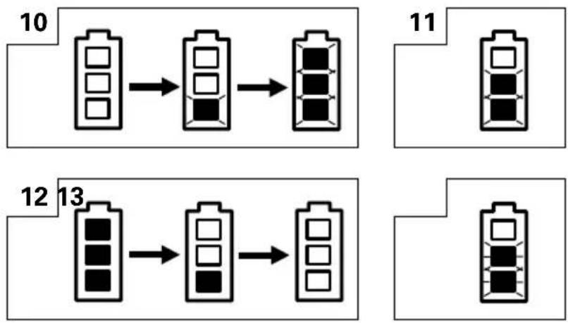
flowchart
graph TD
    A["10: Cell Array"] --> B["11: Cell Array"]
    B --> C["12: Cell Array"]
    C --> D["13: Final Output"]
| English Deutsch Français Italiano | ||||
| 1 | Rechargeable battery | Akkumulator | Batterie rechargeable | Batteria ricaricabile |
| 2 | Latch | Schnapper | Loquet | Fermo |
| 3 | Battery cover | Batterieabdeckung | Couvercle de batterie | Coperchio per la batteria |
| 4 | Terminals | Anschlüsse | Bornes | Terminali |
| 5 | Indication lamp | Anzeiglämpchen | Voyant indicateur | Lampada indicatrice |
| 6 | Handle | Griff | Poignée | Impugnatura |
| 7 | Insert | Einsatz | Insérer | Inserire |
| 8 | Pull out | Herausziehen | Tirer | Estrarre |
| 9 | Push | Drücken | Pousser | Spingere |
| 10 | Insert | Einsetzen | Insérer | Inserire |
| 11 | Pilot lamp | Kontrollampe | Lampe témoin | Spia |
| 12 | Hole for connecting the rechargeable battery | Anschlußloch für Ladebatterir | Orifice de raccordemente de la batterie rechargeable | Foro di collegamento della batteria ricaricabile |
| 13 | Movement | Bewegung | Mouvement | Movimento |
| 14 | Guide sleeve | Führungsmanschette | Manchon-guide | Manicotto guida |
| 15 | Hexagonal hole in the anvil | Sechskantloch in der Schabotte | Orifice hexagonal de la chabotte | Foro esagonale nel basaménto |
| 16 | Driver bit | Dreherspitze | Mèche | Testa avvitatrice |
| 17 | Drill bit | Bohrer | Foret de perçage | Punta del trapano |
| 18 | Drill chuck adapter | Bohrfutteradapter | Adaptateur du mandrin porte-mèche | Adattatore mandrino del trapano |
| 19 | Tighten | Anziehen | Serrer | Stringere |
| 20 | Loosen | Lösen | Desserrer | Allentare |
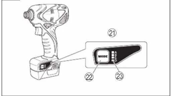
| 21 | Mode switch panel | Modusschalter-Panel | Panneau de changement de mode | Pannello cambio modalità |
| 22 | Mode selection switch | Modusauswahlschalter | Commutateur de sélection de mode | Interruttore selezione modalità |
| 23 | Mode indication lamp | Modus-Anzeiglämpchen | Voyant indicateur de mode | Lampada indicatrice modalità |
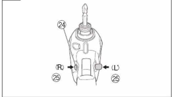
| 24 | Push button | Druckknopf | Poussoir | Tasto da premere |
| 25 | Push | Drücken | Pousser | Spingere |
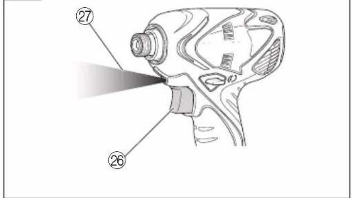
| 26 | Trigger switch | Trigger | Déclencheur | Interruttore |
| 27 | Light | Licht | Témoin | Luce |
flowchart
graph TD
    A["10: Cell Array"] --> B["11: Cell Array"]
    B --> C["12: Cell Array"]
    C --> D["13: Final Output"]
| Nederlands Español | Português | ||
| 1 | Oplaadbare batterij | Batería recargable | Bateria de recarregável |
| 2 | Vergrendeling | Enganche | Lingüeta |
| 3 | Batterijdeksel | Tapa de batería | Tampa da bateria |
| 4 | Aansluitpunten | Terminales | Terminais |
| 5 | Indicatielamp | Indicador luminoso | Luz indicadora |
| 6 | Handgreep | Mango | Cabo |
| 7 | Insteken | Insertar | Inserir |
| 8 | Uittrekken | Sacar | Retirar |
| 9 | Drukken | Presionar | Empurrar |
| 10 | Insteken | Insertar | Inserir |
| 11 | Controlelampje | Lámpara piloto | Lâmpada piloto |
| 12 | Aansluiting voor oplaadbare batterij | Agujero para conectar la batería recargable | Orifício para conectar a batería recarregável |
| 13 | Beweging | Movimiento | Movimento |
| 14 | Geleide ring | Manguito guía | Manga-guia |
| 15 | Zeshoekige opening in het draaistuk | Orificio hexagonal en el yunque | Orifício sextavado na bigorna |
| 16 | Schroefstuk | Punta de destornillador | Chave de fenda |
| 17 | Boorstuk | Broca | Broca |
| 18 | Verloopstuk voor boorhouder | Adaptador de portabrocas | Adaptador para mandril |
| 19 | Aandraaien | Apretar | Apertar |
| 20 | Losdraaien | Aflojar | Afrouxar |
| 21 | Modusschakelpaneel | Panel de cambio de modo | Painel de mudança de modo |
| 22 | Modusselectieschakelaar | Interruptor de selección de modo | Interruptor de selecção de modo |
| 23 | Modusindicatiwlamp | Indicador luminoso de modo | Luz indicadora de modo |
| 24 | Druktoets | Pulsador | Interruptor |
| 25 | Drukken | Presionar | Empurrar |
| 26 | Trekkerschakelaar | Conmutador de gatillo | Interruptor de comando |
| 27 | Licht | Luz | Luz |
| Symbols⚠ WARNINGThe following show symbols used for the machine. Be sure that you understand their meaning before use. | Symbole⚠ WARNUNGDie folgenden Symbole werden für diese Maschine verwendet. Achten Sie darauf, diese vor der Verwendung zu verstehen. | Symboles⚠ AVERTISSEMENTLes symboles suivants sont utilisés pour l’outil.Bien se familiariser avec leur signification avant d’utiliser l’outil. | Simboli⚠ AVVERTENZADi seguito mostriamo i simboli usati per la macchina. Assicurarsi di comprenderne il significato prima dell’uso. | |
 | Read all safety warnings and all instructions.Failure to follow the warnings and instructions may result in electric shock, fire and/or serious injury. | Lesen Sie sämtliche Sicherheitshinweise und Anweisungen durch.Wenn die Warnungen und Anweisungen nicht befolgt werden, kann es zu Stromschlag, Brand und/oder ernsthaftenVerletzungen kommen. | Lire tous les avertissements de sécurité et toutes les instructions.Tout manquement à observer ces avertissements et instructions peut engendrer des chocs électriques, des incendies et/ou des blessures graves. | Leggere tutti gli avvertimenti di sicurezza e tutte le istruzioni.La mancata osservanza degli avvertimenti e delle istruzioni potrebbe essere causa di scosse elettriche, incendi e/o gravi lesioni. |
 | Only for EU countriesDo not dispose of electric tools together with household waste material!In observance of European Directive 2002/96/EC on waste electrical and electronic equipment and its implementation in accordance with national law, electric tools that have reached the end of their life must be collected separately and returned to an environmentally compatible recycling facility. | Nur für EU-LänderWerfen Sie Elektrowerkzeuge nicht in den Hausmüll!Gemäss Europäischer Richtlinie 2002/96/EG über Elektro- und Elektronik-Altgeräte und Umsetzung in nationales Recht müssen verbrauchte Elektrowerkzeuge getrennt gesammelt und einer umweltgerechten Wiederververitung zugeführt werden. | Pour les pays européens uniquementNe pas jeter les appareils électriques dans les ordures ménagères!Conformément à la directive européenne 2002/96/CE relative aux déchets d’équipements électriques ou électroniques (DEEE), et à sa transposition dans la législation nationale, les appareils électriques doivent être collectés à part et être soumis à un recyclage respectueux de l’environnement. | Solo per Paesi UENon gettare le apparecchiature elettriche tra i rifiuti domestici.Secondo la Direttiva Europea 2002/96/CE sui rifiuti di apparecchiature elettriche ed elettroniche e la sua attuazione in conformità alle norme nazionali, le apparecchiature elettriche esauste devono essere raccolte separatamente, al fine di essere reimpiegate in modo eco-compatibile. |
| Symbolen⚠ WAARSCHUWINGHieronder staan symbolen afgebeeld die van toepassing zijn op deze machine. U moet de betekenis hiervan begrijpen voor gebruik. | Símbolos⚠ ADVERTENCIAA continuación se muestran los símbolos usados para la máquina. Asegúrese de comprender su significado antes del uso. | Símbolos⚠ AVISOA seguir aparecem os símbolos utilizados pela máquina. Assimile bem seus significados antes do uso. | ||
 | Lees alle waarschuwingen en instructies aandachtig door.Nalating om de waarschuwingen en instructies op te volgen kan in een elektrische schok, brand en/of ernstig letsel resulteren. | Lea todas las instrucciones y advertencias de seguridad.Si no se siguen las advertencias e instrucciones, podría producirse una descarga eléctrica, un incendio y/o daños graves. | Leia todas as instruções e avisos de segurança.Se não seguir todas as instruções e os avisos, pode provocar um choque eléctrico, incêndio e/ou ferimentos graves. | |
 | Alleen voor EU-landenGeef elektrisch gereedschap niet met het huisvuil mee!Volgens de Europese richtlijn 2002/96/EC inzake oude elektrische en elektronische apparaten en de toepassing daarvan binnen de nationale wetgeving, dient gebruikt elektrisch gereedschap gescheiden te worden ingezameld en te worden afgevoerd naar een recycle bedrijf dat voldoet aan de geldende milieu-eisen. | Sólo para países de la Unión Europea¡No deseche los aparatos eléctricos junto con los residuos domésticos!De conformidad con la Directiva Europea 2002/96/CE sobre residuos de aparatos eléctricos y electrónicos y su aplicación de acuerdo con la legislación nacional, las herramientas eléctricas cuya vida útil haya llegado a su fin se deberán recoger por separado y trasladar a una planta de reciclaje que cumpla con las exigencias ecológicas. | Apenas para países da UENão deite ferramentas eléctricas no lixo doméstico!De acordo com a directiva europeia 2002/96/CE sobre ferramentas eléctricas e electrónicas usadas e a transposição para as leis nacionais, as ferramentas eléctricas usadas devem ser recolhidas em separado e encaminhadas a uma instalação de reciclagem dos materiais ecológica. |
GENERAL POWER TOOL SAFETY WARNINGS
WARNING
Read all safety warnings and all instructions.
Failure to follow the warnings and instructions may result in electric shock, fire and/or serious injury.
Save all warnings and instructions for future reference.
The term "power tool" in the warnings refers to your mains-operated (corded) power tool or battery-operated (cordless) power tool.
1) Work area safety
a) Keep work area clean and well lit.
Cluttered or dark areas invite accidents.
b) Do not operate power tools in explosive atmospheres, such as in the presence of flammable liquids, gases or dust.
Power tools create sparks which may ignite the dust or fumes.
c) Keep children and bystanders away while operating a power tool.
Distractions can cause you to lose control.
2) Electrical safety
a) Power tool plugs must match the outlet.
Never modify the plug in any way. Do not use any adapter plugs with earthed (grounded) power tools.
Unmodified plugs and matching outlets will reduce risk of electric shock.
b) Avoid body contact with earthed or grounded surfaces, such as pipes, radiators, ranges and refrigerators.
There is an increased risk of electric shock if your body is earthed or grounded.
c) Do not expose power tools to rain or wet conditions.
Water entering a power tool will increase the risk of electric shock.
d) Do not abuse the cord. Never use the cord for carrying, pulling or unplugging the power tool. Keep cord away from heat, oil, sharp edges or moving parts.
Damaged or entangled cords increase the risk of electric shock.
e) When operating a power tool outdoors, use an extension cord suitable for outdoor use.
Use of a cord suitable for outdoor use reduces the risk of electric shock.
f) If operating a power tool in a damp location is unavoidable, use a residual current device (RCD) protected supply.
Use of an RCD reduces the risk of electric shock.
3) Personal safety
a) Stay alert, watch what you are doing and use common sense when operating a power tool. Do not use a power tool while you are tired or under the influence of drugs, alcohol or medication. A moment of inattention while operating power tools may result in serious personal injury.
b) Use personal protective equipment. Always wear eye protection.
Protective equipment such as dust mask, non-skid safety shoes, hard hat, or hearing protection used for appropriate conditions will reduce personal injuries.
c) Prevent unintentional starting. Ensure the switch is in the off-position before connecting to power source and/or battery pack, picking up or carrying the tool.
Carrying power tools with your finger on the switch or energising power tools that have the switch on invites accidents.
d) Remove any adjusting key or wrench before turning the power tool on.
A wrench or a key left attached to a rotating part of the power tool may result in personal injury.
e) Do not overreach. Keep proper footing and balance at all times.
This enables better control of the power tool in unexpected situations.
f) Dress properly. Do not wear loose clothing or jewellery. Keep your hair, clothing and gloves away from moving parts.
Loose clothes, jewellery or long hair can be caught in moving parts.
g) If devices are provided for the connection of dust extraction and collection facilities, ensure these are connected and properly used.
Use of dust collection can reduce dust related hazards.
4) Power tool use and care
a) Do not force the power tool. Use the correct power tool for your application.
The correct power tool will do the job better and safer at the rate for which it was designed.
b) Do not use the power tool if the switch does not turn it on and off.
Any power tool that cannot be controlled with the switch is dangerous and must be repaired.
c) Disconnect the plug from the power source and/or the battery pack from the power tool before making any adjustments, changing accessories, or storing power tools.
Such preventive safety measures reduce the risk of starting the power tool accidentally.
d) Store idle power tools out of the reach of children and do not allow persons unfamiliar with the power tool or these instructions to operate the power tool.
Power tools are dangerous in the hands of untrained users.
e) Maintain power tools. Check for misalignment or binding of moving parts, breakage of parts and any other condition that may affect the power tools operation.
If damaged, have the power tool repaired before use.
Many accidents are caused by poorly maintained power tools.
f) Keep cutting tools sharp and clean.
Properly maintained cutting tools with sharp cutting edges are less likely to bind and are easier to control.
g) Use the power tool, accessories and tool bits etc. in accordance with these instructions, taking into account the working conditions and the work to be performed.
Use of the power tool for operations different from those intended could result in a hazardous situation.
5) Battery tool use and care
a) Recharge only with the charger specified by the manufacturer.
A charger that is suitable for one type of battery pack may create a risk of fire when used with another battery pack.
b) Use power tools only with specifically designated battery packs.
Use of any other battery packs may create a risk of injury and fire.
c) When battery pack is not in use, keep it away from other metal objects like paper clips, coins, keys, nails, screws, or other small metal objects that can make a connection from one terminal to another.
Shorting the battery terminals together may cause burns or a fire.
d) Under abusive conditions, liquid may be ejected from the battery; avoid contact. If contact accidentally occurs, flush with water. If liquid contacts eyes, additionally seek medical help.
Liquid ejected from the battery may cause irritation or burns.
6) Service
a) Have your power tool serviced by a qualified repair person using only identical replacement parts.
This will ensure that the safety of the power tool is maintained.
PRECAUTION
Keep children and infirm persons away.
When not in use, tools should be stored out of reach of children and infirm persons.
PRECAUTIONS FOR ELECTRONIC PULSE DRIVER
-
Hold power tool by insulated gripping surfaces, when performing an operation where the fastener may contact hidden wiring. Fasteners contacting a "live" wire may make exposed metal parts of the power tool "live" and could give the operator an electric shock.
-
This is a portable tool for drilling, tightening and loosenig screws. Use it only for these operations.
-
Use the earplugs if using for a long time.
-
One-hand operation is extremely dangerous; hold the unit firmly with both hands when operating.
-
After installing the driver bit, pull lightly out the bit to make sure that it does not come loose. If the bit is not installed properly, it can come loose during use, which can be dangerous.
-
Use the bit that matches the screw.
-
Tightening a screw with the tool at an angle to that tool can damage the head of the screw and the proper force will not be transmitted to the screw. Tighten with this tool lined up straight with the screw.
-
Always charge the battery at a temperature of 0 - 40°C.
A temperature of less than 0^ C will result in over charging which is dangerous. The battery cannot be charged at a temperature greater than 40^ C. The most suitable temperature for charging is that of 20 – 25^ C.
- Do not use the charger continuously.
When one charging is completed, leave the charger for about 15 minutes before the next charging of battery.
-
Do not allow foreign matter to enter the hole for connecting the rechargeable battery.
-
Never disassemble the rechargeable battery and charger.
-
Never short-circuit the rechargeable battery. Short-circuiting the battery will cause a great electric current and overheat. It results in burn or damage to the battery.
-
Do not dispose of the battery in fire. If the battery burnt, it may explode.
-
Bring the battery to the shop from which it was purchased as soon as the post-charging battery life becomes too short for practical use. Do not dispose of the exhausted battery.
-
Using an exhausted battery will damage the charger.
-
When drilling in wall, floor or ceiling, check for buried electric power cord, etc.
CAUTION ON LITHIUM-ION BATTERY
To extend the lifetime, the lithium-ion battery equips with the protection function to stop the output.
In the cases of 1 to 3 described below, when using this product, even if you are pulling the switch, the motor may stop. This is not the trouble but the result of protection function.
-
When the battery power remaining runs out, the motor stops. In such a case, charge it up immediately.
-
If the tool is overloaded, the motor may stop. In this case, release the switch of tool and eliminate causes of overloading. After that, you can use it again.
-
If the battery is overheated under overload work, the battery power may stop. In this case, stop using the battery and let the battery cool. After that, you can use it again.
Furthermore, please heed the following warning and caution.
WARNING
In order to prevent any battery leakage, heat generation, smoke emission, explosion and ignition beforehand, please be sure to heed the following precautions.
- Make sure that swarf and dust do not collect on the battery.
During work make sure that swarf and dust do not fall on the battery.
○Make sure that any swarf and dust falling on the power tool during work do not collect on the battery.
○Do not store an unused battery in a location exposed to swarf and dust.
Before storing a battery, remove any swarf and dust that may adhere to it and do not store it together with metal parts (screws, nails, etc.).
-
Do not pierce battery with a sharp object such as a nail, strike with a hammer, step on, throw or subject the battery to severe physical shock.
-
Do not use an apparently damaged or deformed battery.
-
Do not use the battery in reverse polarity.
-
Do not connect directly to an electrical outlets or car cigarette lighter sockets.
-
Do not use the battery for a purpose other than those specified.
-
If the battery charging fails to complete even when a specified recharging time has elapsed, immediately stop further recharging.
-
Do not put or subject the battery to high temperatures or high pressure such as into a microwave oven, dryer, or high pressure container.
-
Keep away from fire immediately when leakage or foul odor are detected.
-
Do not use in a location where strong static electricity generates.
-
If there is battery leakage, foul odor, heat generated, discolored or deformed, or in any way appears abnormal during use, recharging or storage, immediately remove it from the equipment or battery charger, and stop use.
CAUTION
- If liquid leaking from the battery gets into your eyes, do not rub your eyes and wash them well with fresh clean water such as tap water and contact a doctor immediately. If left untreated, the liquid may cause eye-problems.
- If liquid leaks onto your skin or clothes, wash well with clean water such as tap water immediately. There is a possibility that this can cause skin irritation.
- If you find rust, foul odor, overheating, discolor, deformation, and/or other irregularities when using the battery for the first time, do not use and return it to your supplier or vendor.
WARNING
If an electrically conductive foreign object enters the terminals of the lithium ion battery, a short-circuit may occur resulting in the risk of fire. Please observe the following matters when storing the battery.
○Do not place electrically conductive cuttings, nails, steel wire, copper wire or other wire in the storage case.
○Either install the battery in the power tool or store by securely pressing into the battery cover until the ventilation holes are concealed to prevent short-circuits (See Fig. 1).
SPECIFICATIONS
Although this machine includes 20 operation modes, up to four of them can be switched using the mode selection switch. Four modes that are suitable for commonly performed operations have been set as factory default operation mode. With an optional communication adaptor, you can freely select your desired operation modes. For details, refer to "Mode selection and rewriting functions" on page 10.
POWER TOOL
| Model WM10DBL | ||||
| Battery type BCL1015 BCL1030M | ||||
| Capacity *1 | Electronic pulse mode | Wood screw | ø3.8 × 50 mm | |
| Bolt mode | Ordinary bolt M4 - M8 | |||
| High-strength bolt | M4 - M6 | |||
| Self drilling screw mode | Small drilling screw | ø5 | ||
| Drill mode Steel dr | Woodwork drilling | ø12 | ||
| Iling ø5 | ||||
| Mortar drilling ø6 | ||||
| Electronic clutch mode *2 | Small screw M6 | |||
| Tightening torque (Maximum) [when fully charged at 20°C temp] | Electronic pulse mode | 19 N·m {194 kgf·cm} | ||
| Bolt mode [Tightening time: 3 sec.] | 20 N·m {204 kgf·cm} [Tightening is M8 high-strength bolt (strength grade 12.9) Hexagon socket used] | |||
| Self drilling screw mode | 14 N·m {143 kgf·cm} | |||
| Drill mode 1.6 N·m {16 kgf·cm} 2.5 | N·m {25 kgf·cm} | |||
| Electronic clutch mode *2 | 10-point clutch 1 - 6 N·m {10 - 61 kgf·cm} | |||
| Edge shape | Width across flat 6.35, bit insertion shape | |||
| Type of motor | DC motor | |||
| No-load speed [when fully charged at 20°C temp] | Electronic pulse mode | 0 - 2200 min-1 | ||
| Bolt mode | 0 - 1300 min-1 | |||
| Self drilling screw mode | 0 - 2200 min-1 | |||
| Drill mode | 0 - 2200 min-1 | |||
| Electronic clutch mode *2 | 0 - 1140 min-1 | |||
| Number of blows [when fully charged at 20°C temp] | Electronic pulse mode | 0 - 1090 min-1 | ||
| Bolt mode | 0 - 1030 min-1 | |||
| Self drilling screw mode | 0 - 1090 min-1 | |||
| Rechargeable battery | BCL1015: Li-ion 10.8 V (1.5 Ah, 3 cells) | BCL1030M: Li-ion 10.8 V (3.0 Ah, 6 cells) | ||
| Dimensions of the tool Entire length × height × center height | 139 mm×216 mm×29 mm (BCL1015 attached) | 139 mm×233 mm×29 mm (BCL1030M attached) | ||
| Weight | 1.0 kg (BCL1015 attached) | 1.2 kg (BCL1030M attached) | ||
| LED light | White LED | |||
*1: The machine capability of BCL1015 becomes lower than that of BCL1030M in a high-load operation, because both machines are of the same battery voltage but differ in internal structure.
*2: The Electronic clutch mode is not of the factory default operation mode.
CHARGER
| Model UC10SL2 / UC10SFL | |
| Charging voltage 10.8 V | |
| Weight 0.35 kg | |
STANDARD ACCESSORIES
In addition to the main unit (1), the package contains the accessories listed in the table below.
| WM10DBL(2LCSK) | 1 Charger (UC10SL2 or UC10SFL) ..... 12 Battery (BCL1015) ..... 23 Plastic case..... 14 Battery cover ..... 1 |
| WM10DBL(2LMSK) | 1 Charger (UC10SL2 or UC10SFL) ..... 12 Battery (BCL1030M) ..... 23 Plastic case..... 14 Battery cover ..... 1 |
| WM10DBL(NN) | Without charger, battery, plastic case and battery cover. |
Standard accessories are subject to change without notice.
OPTIONAL ACCESSORIES (Sold separately)
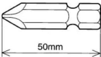
- Plus driver bit
| Bit No. Code No. | |
| No. 2 992671 | |
| No. 3 992672 | |
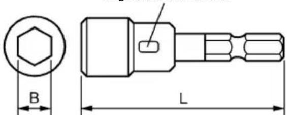
- Hexagonal socket
| Part Name | Engraved characters | L | B | Code No. |
| 5 mm Hexagonal socket 8 | 65 8 996177 | |||
| 6 mm Hexagonal socket | 10 | 65 | 10 | 985329 |
| 5/16" Hexagonal socket | 12 | 65 | 12 | 996178 |
| 8 mm Hexagonal socket | 13 | 65 | 13 | 996179 |
Engraved characters
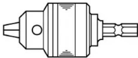
3. Drill chuck adapter set: Code No. 321823
Use drill bits available on the local market.
natural_image
Technical line drawing of a mechanical component with no visible text or symbolsOptional accessories are subject to change without notice.
APPLICATION
○Driving and removing of small screws, small bolts, machine screws, wood screws, tapping screws, etc.
○Drilling of various woods.
○Drilling of various metals.
BATTERY REMOVAL/INSTALLATION
1. Battery removal
Hold the handle tightly and push the battery latch to remove the battery (see Figs. 1 and 2).
CAUTION:
Never short-circuit the battery.
2. Battery installation
Insert the battery while observing its polarities (see Fig. 2).
CHARGING
Before using the Electronic pulse driver, charge the battery as follows.
- Connect the charger's power cord to the receptacle. When connecting the plug of the charger to a receptacle, the pilot lamp will blink in red (At 1-second intervals).
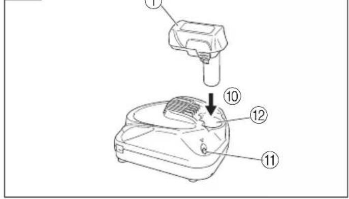
2. Insert the battery into the charger.
Firmly insert the battery into the charger till it contacts the bottom of the charger as shown in Fig. 3.
3. Charging
When inserting a battery in the charger, the pilot lamp will light up continuously in red.
When the battery becomes fully recharged, the pilot lamp will blink in red (At 1-second intervals). (See Table 1)
(1) Pilot lamp indication
The indications of the pilot lamp will be as shown in Table 1, according to the condition of the charger or the rechargeable battery.
Table 1
| Indications of the pilot lamp | ||||
| Pilot lamp(red) | Before charging | Blinks | Lights for 0.5 seconds. Does not light for 0.5 seconds. (off for 0.5 seconds) | |
| While charging | Lights | Lights continuously | ||
| Charging complete | Blinks | Lights for 0.5 seconds. Does not light for 0.5 seconds. (off for 0.5 seconds) | ||
| Overheat standby | Blinks | Lights for 1 second. Does not light for 0.5 seconds. (off for 0.5 seconds) | Battery overheated. Unable to charge. (Charging will commence when battery cools) | |
| Charging impossible | Flickers | Lights for 0.1 seconds. Does not light for 0.1 seconds. (off for 0.1 seconds) | Malfunction in the battery or the charger | |
(2) Regarding the temperature of the rechargeable battery The temperatures for rechargeable batteries are as shown in the Table 2, and batteries that have become hot should be cooled for a while before being recharged.
Table 2 Recharging ranges of batteries
| Rechargeable batteries | Temperatures at which the battery can be recharged |
| BCL1015, BCL1030M 0°C – 50°C | |
(3) Regarding recharging time Depending on the combination of the charger and batteries, the charging time will become as shown in Table 3.
Table 3 Charging time (At 20°C)
| Battery\Charger | UC10SL2 UC | 10SFL |
| BCL1015 | Approx. 30 min. | Approx. 40 min. |
| BCL1030M | Approx. 60 min. | Approx. 80 min. |
NOTE
The charging time may vary according to temperature and power source voltage.
-
Disconnect the charger's power cord from the receptacle.
-
Hold the charger firmly and pull out the battery. NOTE
Be sure to pull out the battery from the charger after use, and then keep it.
Regarding electric discharge in case of new batteries, etc.
As the internal chemical substance of new batteries and batteries that have not been used for an extended period is not activated, the electric discharge might be low when using them the first and second time. This is a temporary phenomenon, and normal time required for recharging will be restored by recharging the batteries 2 – 3 times.
How to make the batteries perform longer
(1) Recharge the batteries before they become completely exhausted.
When you feel that the power of the tool becomes weaker, stop using the tool and recharge its battery. If you continue to use the tool and exhaust the electric current, the battery may be damaged and its life will become shorter.
(2) Avoid recharging at high temperatures.
A rechargeable battery will be hot immediately after use. If such a battery is recharged immediately after use, its internal chemical substance will deteriorate, and the battery life will be shortened. Leave the battery and recharge it after it has cooled for a while.
CAUTION
○If the battery is charged while it is heated because it has been left for a long time in a location subject to direct sunlight or because the battery has just been used, the pilot lamp of the charger lights for 1 second, does not light for 0.5 seconds (off for 0.5 seconds). In such a case, first let the battery cool, then start charging.
When the pilot lamp flickers (at 0.2-second intervals), check for and take out any foreign objects in the charger's battery connector. If there are no foreign objects, it is probable that the battery or charger is malfunctioning. Take it to your authorized Service Center.
○Since the built-in micro computer takes about 3 seconds to confirm that the battery being charged with UC10SL2 / UC10SFL is taken out, wait for a minimum of 3 seconds before reinserting it to continue charging. If the battery is reinserted within 3 seconds, the battery may not be properly charged.
PRIOR TO OPERATION
- Preparing and checking the work environment
Make sure that the work site meets all the conditions laid forth in the precautions.
- Checking the battery
Make sure that the battery is installed firmly. If it is at all loose it could come off and cause an accident.
3. Installing the bit
○Driver bit
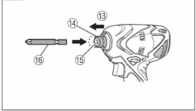
Always follow the following procedure to install driver bit. (Fig. 4)
(1) Pull the guide sleeve back.
(2) Insert the bit into the hexagonal hole in the anvil.
(3) Release the guide sleeve and it returns to its original position.
CAUTION:
If the guide sleeve does not return to its original position, then the bit is not installed properly.
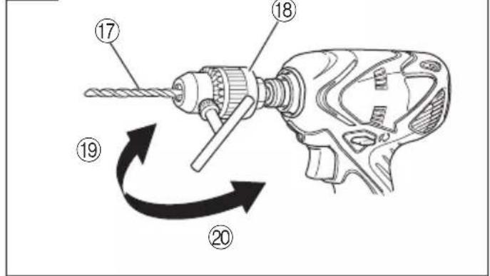
○Drill bit
- A drill with hexagonal shank can be attached directly to the tool.
• To attach a drill without hexagonal shank, you need to have the drill chuck adapter set sold separately.
(1) Insert the drill bit into the chuck.
(2) Use the chuck key to secure the drill bit, tightening the chuck by each of the three holes in turn. (Fig. 5)
- Use an iron drill to make a pilot hole for a wood screw or a 10 mm or smaller hole.
(1) Insert the drill bit into the chuck.
(2) Use the chuck key to secure the drill bit, tightening the chuck by each of the three holes in turn. (Fig. 5)
HOW TO USE
How to make the batteries perform longer
○Recharge the batteries before they become completely exhausted.
When you feel that the power of the tool becomes weaker, stop using the tool and recharge its battery. If you continue to use the tool and exhaust the electric current, the battery may be damaged and its life will become shorter.
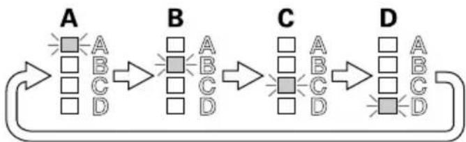
1. Mode selection and rewriting functions
The operation mode is switched each time you press the mode selection switch provided on the side of the tool body.
Select an operation mode corresponding to your desired operation (Fig. 6).
flowchart
graph LR
    A["Step A: Square with A, B, C, D"] --> B["Step B: Square with A, B, C, D"]
    B --> C["Step C: Square with A, B, C, D"]
    C --> D["Step D: Square with A, B, C, D"]
NOTE:
The mode selection can be switched only after installing the charger to the body and once pulling the switch.
(1) Default setting for operation mode
The following four modes are set as default operation mode on this machine.
| Symbol | Operation mode | Example of applicable operation |
| A | Electronic pulse "3" | Tightening of wood screws |
| B Bolt | "Continuous" Tightening of bolts | |
| C | Self drilling screw "2" | Tightening of self drilling screw |
| D Drill | Drilling | |
NOTE:
○The tightening torque obtained in an actual tightening operation varies with the screw or clamping member used.
Try to tighten a few screws to confirm the appropriate tightening torque.
○Use the Bolt mode to tighten bolts.
○Mode switching is impossible if the mode selection switch is operated with the switch turned on. Be sure to turn off the switch before performing mode switching.
(2) Built-in operation modes and mode rewriting function of this product
The machine includes 20 operation modes in total. The setting of each mode is described below.
You can freely select up to four operation modes by using an optional communication adaptor. It is also possible to limit the number of switchable modes to one or two, or to set all of the four modes to a same operation mode.
List of built-in operation modes
means default operation mode.
| No. | Operation mode | Maximum torque | No-lode speed | Number of blows | Application | ||
| 1 | Electronic pulse 2 mode | 1 | 13N·m {133 kgf·cm} | 0 - 1300 min ^-1 | 1090 min ^-1 | Wood screw tightening | Tightening screw shorter than 32 mm |
| 2 | 19N·m {194 kgf·cm} | 0 - 2200 min ^-1 | 1050 min ^-1 | Tightening of 32 - 50 mm screw | |||
| 3 | 3 | Tightening of 50 mm screw | |||||
| 4 | Bolt mode *1 | 1 | 10N·m {102 kgf·cm} | 0 - 770 min ^-1 | 1030 min ^-1 | Bolt Ordinary tightening | bolt : M4 - M8 high-strength bolt : M4 - M6 |
| 5 | 2 | 15N·m {153 kgf·cm} | 0 - 1040 min ^-1 | ||||
| 6 | 3 | 20N·m {204 kgf·cm} | 0 - 1300 min ^-1 | ||||
| 7 | Continuous | 20N·m {204 kgf·cm} | |||||
| 8 | Self drilling screw mode *2 | 1 | 3.5N·m {36 kgf·cm} | 0 - 2200 min ^-1 | 1090 min ^-1 | Self drilling screw tightening | ø3.5 |
| 9 | 2 | 14N·m {143 kgf·cm} | ø4 - ø5 | ||||
| 10 | Drill mode *3 | — | 1.6N·m {16 kgf·cm}2.5N·m {25 kgf·cm} | 0 - 2200 min ^-1 | — | Drilling Wood | ø12, Metal ø5, Mrotar ø6 |
| 11 | Electronic clutch mode *4 | 1 | 1 N·m {10 kgf·cm} | 0 - 250 min ^-1 | Tightening machine screw | -M6 | |
| 12 | 2 | 1.4N·m {14 kgf·cm} | 0 - 350 min ^-1 | ||||
| 13 | 3 | 1.8N·m {18 kgf·cm} | 0 - 450 min ^-1 | ||||
| 14 | 4 | 2.3N·m {23 kgf·cm} | 0 - 550 min ^-1 | Tightening tapping screw | |||
| 15 | 5 | 2.8N·m {29 kgf·cm} | 0 - 650 min ^-1 | ||||
| 16 | 6 | 3.3N·m {34 kgf·cm} | 0 - 750 min ^-1 | ||||
| 17 | 7 | 3.9N·m {40 kgf·cm} | 0 - 850 min ^-1 | Fixing of gypsum board | |||
| 18 | 8 | 4.6N·m {47 kgf·cm} | 0 - 950 min ^-1 | ||||
| 19 | 9 | 5.3N·m {54 kgf·cm} | 0 - 1040 min ^-1 | ||||
| 20 | 10 | 6 N·m {61 kgf·cm} | 0 - 1140 min ^-1 | ||||
The maximum torque in the list is the set maximum torque that is generated by the tool itself in a selected operation mode. The tightening torque obtained in an actual tightening operation varies with the screw or clamping member used. Therefore, you need to try to tighten a few screws for confirmation.
*1: The Bolt mode 1, 2, and 3 are to be stopped by ten times of striking for accuracy improvement of tightening torque.
*2: Before fixing a thin plate with a self drilling screw, make sure that the thickness of the plate is suitable for the screw diameter.
*3: When installing BCL1015: 1.6 N·m {16 kgf·cm}, When installing BCL1030M: 2.5 N·m {25 kgf·cm}
*4: With the electronic clutch mode 4-10 the tool may execute reverse rotation briefly when the load increases in order to reduce a risk of screw-head damage.
The tool starts up in low rotation speed and tightens softly.
The motor automatically stops rotating when the torque reaches to the pre-set value in order to reduce over tightening.
The clutch sound such as of the mechanical type will not be generated.
You can change the switchable operation modes with the dedicated software by connecting the communication adaptor between the tool and PC.
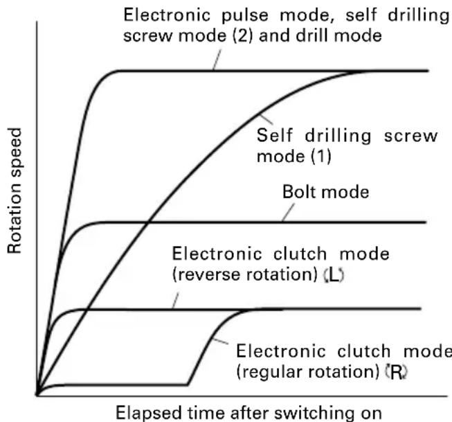
2. Characteristics of Electronic Pulse Driver
Unlike a conventional impact driver, the electronic pulse driver generates the striking force by rotating the motor in regular and reverse directions repeatedly. This mechanism has helped to provide quieter operation.
The following characteristics are uncommon to a conventional impact driver, however these are not signs of malfunction.
○The tool tends to be heated by continuous screw tightening.
To protect the motor and electronic parts that control the motor operation, this tool is equipped with a temperature protection circuit.
Depending on the screw and material being screwed, the striking operation may start early.
Since the striking operation causes temperature increase of the motor and electronic parts, the temperature protection circuit may be activated early.
Refer to "1. Continuous operation" on page 13 for recovering from the operation stop caused by the temperature protection circuit.
Also, the electronic pulse driver controls the motor rotation consistently to provide the optimum operation for each mode.
Because of this, the following cases can occur during operation.
○The behavior at operation start differs by the mode. The self drilling screw mode (1) gradually increases the speed.
The electronic clutch mode (regular rotation) rotates the motor at a very slow speed for a certain period after the start and then increases the speed.
On the other hand, the electronic clutch mode (reverse rotation) meets the preset rotation speed immediately after the start.
○The tool may not return to the initial status from the striking operation.
When the bit or socket is removed from the screw or bolt while the switch is being pulled, the tool may continue the striking operation.
To return to the initial status, turn off the switch and then start the next operation.
○Motor rotation speed does not decrease even when the remaining battery power becomes low. Since this tool adopts the constant-speed control, the rotation speed is almost unchanged even when the remaining amount of the battery becomes low. This allows users to operate the tool efficiently until the battery runs down. However, it is difficult to know the remaining battery power from the rotation speed and the tool may stop suddenly during work.
○The tool stops automatically when the electronic clutch is actuated.
Quiet screw tightening can be performed without clutch sound generated by the mechanical type.
The tool stops automatically when the clutch is actuated. If you continue to use the tool, turn off the switch once and turn it on again. When the tool does not operate even without load, the remaining amount of the battery is low. In this case, recharge the battery immediately.
3. Check the rotational direction
The bit rotates clockwise (viewed from the rear side) by pushing the R-side of the push button. The L-side of the push button is pushed to turn the bit counterclockwise. (See Fig. 7) (The (L) and (R) marks are provided on the body.)
CAUTION:
The push button can not be switched while the tool is turning. To switch the push button, stop the tool, then set the push button.
4. Switch operation
○When the trigger switch is depressed, the tool rotates. When the trigger is released, the tool stops.
☐The rotational speed can be controlled by varying the amount that the trigger switch is pulled. Speed is low when the trigger switch is pulled slightly and increases as the trigger switch is pulled more.
5. Using the light
Pull the trigger switch to light up the light. The light keeps on lighting while the trigger switch is being pulled. The light goes out after releasing the trigger switch. (Fig. 8)
CAUTION:
Do not expose directly your eyes to the light by looking into the light. If your eyes are continuously exposed to the light, your eyes will be hurt.
6. Tightening and loosening screws
Install the bit that matches the screw, line up the bit in the grooves of the head of the screw, then tighten it. Push the tool just enough to keep the bit fitting the head of the screw.
CAUTION:
○Applying the tool for too long tightens the screw too much and can break it.
Tightening a screw with the tool at an angle to that screw can damage the head of the screw and the proper force will not be transmitted to the screw.
Tighten with this tool lined up straight with the screw.
○Use the bit that fits the cross recess on the screw head. Make sure to use an appropriate bit especially when tightening self drilling screws since using an inappropriate bit can topple the screws.
7. Work amount possible with one charging
The following table shows the approximate amount of work to be carried out by the tool with one charging. (The number of screws tightened and that of boring operations differ slightly according to the hardness of wood or metal, the ambient temperature, the charger properties, etc.)
| Operation mode Operation | Battery | BCL1015 BCL1030M | |||
| Electronic pulse mode [3] | Wood screw tightening 3.8 × 50 | Lauan Approx. 300 | Approx. 700 | ||
| Bolt mode [3] Bolt tightening | M8 × 30 S | 10C Approx. 100 | Approx. 240 | ||
| Self drilling screw mode [2] | Self drilling screw tightening 4 × 16 | C-channel t2.3 + SPCC t1.6 | Approx. 120 | Approx. 280 | |
| Drill mode | Woodwork drilling 12 American pine | t18 Approx. 220 | Approx. 510 | ||
| Steel drilling 5 | SPCC t1.6 | Approx. 95 | Approx. 220 | ||
| Electronic clutch mode | Machine screw tightening M6 × 12 S10C | Approx. 1670 | Approx. 3900 | ||
ABOUT BATTERY BCL1030M
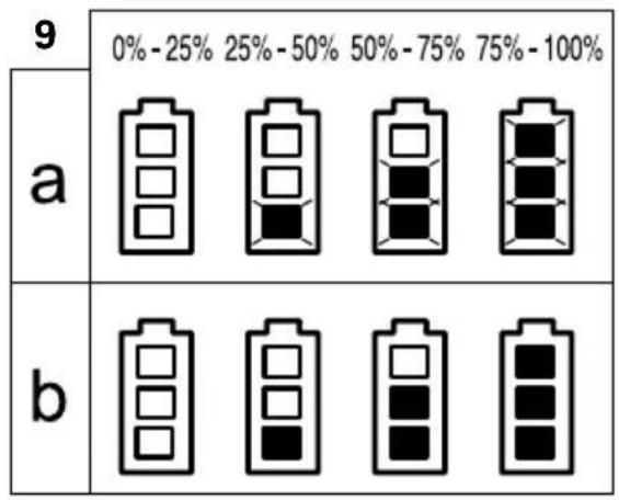
1. Battery capacity indicator
Fig. 9-a When recharging, During pause
Fig. 9-b When using tools
( ■: Lights, □Goes out, :■inks, (2-second period), ■: Blinks rapidly (0.5-second period))
(1) When recharging (Fig. 10)
The indication lamps will blink and indicate the charging amount to the battery.
(2) During pause (Fig. 11)
The indication lamps will always blink and indicate the remaining capacity of the battery.
(3) When using tools (Fig. 12)
When turning on the switch of the cordless tool, the indication lamps will light and indicate the remaining capacity of the battery. After three seconds or so from releasing the switch, the indication lamps will start blinking.
2. Protective function
In the following case 1 and case 2, the motor of the cordless tool may stop (indication lamps are turned off) during operation, however, this is not a sign of failure, but is caused by activation of the protective function.
(1) The motor stops when the remaining battery capacity becomes low (battery voltage decreased to 6V). In this case, recharge the battery promptly.
(2) The motor may stop when the cordless tool is overloaded. In this case, release the switch and eliminate the cause of the overload. After that, you can use the tool again.
- Indication of trouble (Fig. 13)
When the indication lamps blink rapidly (0.5-second period), it may suggest a battery failure. Please take the battery to the dealer you purchased from.
4. How to determine the battery usage life
When the operating time of the battery becomes significantly short after correctly recharging the battery, it may indicate the end of the battery life and we recommend you to purchase a new battery.
NOTE:
If left unused for a long period, the battery may become too weak to light up or blink the indication lamps used to show the remaining power. The lamps will light back up or blink once the battery is recharged.
Hints on how to make the battery last
(1) Recharge the Battery Before it Becomes Completely Discharged.
When you feel that the power of the tool weakens, stop using the tool and recharge the battery.
If you continue using the tool and discharge the battery, the battery will be damaged and its life will be shortened.
(2) Avoid Recharging the Battery at High Temperatures. The battery will be hot immediately after using the tool.
If you recharge the battery too soon, the chemical substances inside the battery will deteriorate, and the life of the battery will be shortened.
Let the battery take rest and cool down before recharging it.
* If there is anything you do not understand about this product, please feel free to inquire with your nearest authorized Service Agent.
OPERATIONAL CAUTIONS
1. Continuous operation
When you perform the striking operation continuously, the temperature protection circuit may be activated early. (Refer to "2. Characteristics of Electronic Pulse Driver" on page 11.)
When the activated temperature protection circuit stops the tool, the LED light flashes to indicate that the tool is heated to high temperature. The LED light goes off automatically after approx. 30 seconds.
When you perform continuous operation, allow the tool to rest for around 15 minutes at a replacement of rechargeable battery.
NOTE:
When the tool is stopped by the activated temperature protection circuit, allow the tool to cool sufficiently. You can use the tool again when it cools down.
While the tool is not cooled sufficiently, it cannot start up by turning the switch to on. The LED light flashes while the switch is turned on. Please wait until the tool cools down sufficiently.
○Do not touch the nose part of the tool during continuous operation. It is heated to high temperature.
2. Cautions on use of the speed control switch
This switch has a built-in, electronic circuit which steplessly varies the rotation speed. Consequently, when the switch trigger is pulled only slightly (low speed rotation) and the motor is stopped while continuously driving in screws, the components of the electronic circuit parts may overheat and be damaged.
3. Holding the tool and applying the pressing force
Make sure to hold the tool securely with your both hands, and keep the tool straight to a screw or bolt. There is no need to press the tool excessively against materials.
Be careful not to apply excessive pressing/prying force to the tool. It may damage the tool.
MAINTENANCE AND INSPECTION
1. Inspecting the tool
Since use of a dull tool will degrade efficiency and cause possible motor malfunction, sharpen or replace the tool as soon as abrasion is noted.
2. Inspecting the mounting screws
Regularly inspect all mounting screws and ensure that they are properly tightened. Should any of the screws be loose, retighten them immediately. Failure to do so may result in serious hazard.
3. Maintenance of the motor
The motor unit winding is the very "heart" of the power tool.
Exercise due care to ensure the winding does not become damaged and/or wet with oil or water.
4. Cleaning of the outside
When the tool is stained, wipe with a soft dry cloth or a cloth moistened with soapy water. Do not use chloric solvents, gasoline or paint thinner, as they melt plastics.
5. Storage
Store the tool in a place in which the temperature is less than 40^ C, and out of reach of children.
NOTE
Make sure that the battery is fully charged when stored for a long period (3 months or more). The battery with smaller capacity may not be able to be charged when used, if stored for a long period.
6. Service parts list
CAUTION:
Repair, modification and inspection of HiKOKI Power Tools must be carried out by a HiKOKI Authorized Service Center.
This Parts List will be helpful if presented with the tool to the HiKOKI Authorized Service Center when requesting repair or other maintenance.
In the operation and maintenance of power tools, the safety regulations and standards prescribed in each country must be observed.
MODIFICATIONS:
HiKOKI Power Tools are constantly being improved and modified to incorporate the latest technological advancements.
Accordingly, some parts may be changed without prior notice.
Important notice on the batteries for the HiKOKI cordless power tools
Please always use one of our designated genuine batteries. We cannot guarantee the safety and performance of our cordless power tool when used with batteries other than these designated by us, or when the battery is disassembled and modified (such as disassembly and replacement of cells or other internal parts).
GUARANTEE
We guarantee HiKOKI Power Tools in accordance with statutory/country specific regulation. This guarantee does not cover defects or damage due to misuse, abuse, or normal wear and tear. In case of complaint, please send the Power Tool, undismantled, with the GUARANTEE CERTIFICATE found at the end of this Handling instruction, to a HiKOKI Authorized Service Center.
NOTE:
Due to HiKOKI's continuing program of research and development, the specifications herein are subject to change without prior notice.
Information concerning airborne noise and vibration
The measured values were determined according to EN60745 and declared in accordance with ISO 4871.
Measured A-weighted sound power level: 83 dB (A)
Measured A-weighted sound pressure level: 72 dB (A)
Uncertainty KpA: 3 dB (A).
Wear ear protection.
Vibration total values (triax vector sum) determined according to EN60745.
Impact tightening of fasteners of the maximum capacity of the tool:
Vibration emission value h = 11.0 m/s
Uncertainty K = 1.5 m/s ^2
The declared vibration total value has been measured in accordance with a standard test method and may be used for comparing one tool with another.
It may also be used in a preliminary assessment of exposure.
WARNING
○The vibration emission during actual use of the power tool can differ from the declared total value depending on the ways in which the tool is used.
○Identify safety measures to protect the operator that are based on an estimation of exposure in the actual conditions of use (taking account of all parts of the operating cycle such as the times when the tool is switched off and when it is running idle in addition to the trigger time).
natural_image
Technical line drawing of a mechanical component with no visible text or symbolsflowchart
graph LR
    A["Step A: Square ABCD"] --> B["Step B: Square ABCD"]
    B --> C["Step C: Square ABCD"]
    C --> D["Step D: Square ABCD"]
HINWEIS:
Vibrationsemissionswert a h = 11,0 m/s^2
natural_image
Technical line drawing of a mechanical component with no visible text or symbolsflowchart
graph LR
    A["Step A: Square with light squares"] --> B["Step B: Square with light squares"]
    B --> C["Step C: Square with light squares"]
    C --> D["Step D: Square with light squares"]
REMARQUE :
natural_image
Technical line drawing of a mechanical component with no visible text or symbolsflowchart
graph LR
    A["Step A: Square ABCD"] --> B["Step B: Square ABCD"]
    B --> C["Step C: Square ABCD"]
    C --> D["Step D: Square ABCD"]
NOTA:
natural_image
Technical line drawing of a mechanical component with no visible text or symbolsflowchart
graph LR
    A["Step A: Square ABCD"] --> B["Step B: Square ABCD"]
    B --> C["Step C: Square ABCD"]
    C --> D["Step D: Square ABCD"]
OPMERKING:
natural_image
Technical line drawing of a mechanical component with no visible text or symbolsnatural_image
Technical line drawing of a mechanical component with no visible text or symbolsline
| Tempo decorrido depois de ligar | Modo de impulso electrónico, modo de parafuso auto-roscante (2) e modo berbequim | Modo de parafuso auto-roscante (1) | Modo de parafuso | Modo de embraiagem electrónica (rotação inversa) (L) | Modo de embraiagem electrónica (rotação normal) (R) | | ------------------------------ | ---------------------------------------------------------------------- | ------------------------------- | --------------- | --------------------------------------------- | --------------------------------------------- | | 0 | 0 | 0 | 0 | 0 | 0 | | 1 | ~0.85 | ~0.65 | ~0.45 | ~0.3 | ~0.15 | | 2 | ~0.95 | ~0.75 | ~0.55 | ~0.4 | ~0.2 | | 3 | ~0.98 | ~0.85 | ~0.65 | ~0.5 | ~0.25 | | 4 | ~0.99 | ~0.90 | ~0.75 | ~0.6 | ~0.3 | | 5 | ~0.995 | ~0.95 | ~0.85 | ~0.7 | ~0.35 | | 6 | ~0.998 | ~0.98 | ~0.90 | ~0.8 | ~0.4 | | 7 | ~0.999 | ~0.99 | ~0.95 | ~0.9 | ~0.45 | | 8 | ~0.9995 | ~0.995 | ~0.98 | ~1.0 | ~0.5 | | 9 | ~0.9998 | ~0.998 | ~0.99 | ~1.1 | ~0.55 | | 10 | 1.0 | 1.0 | 1.0 | 1.2 | 1.0 | | 11 | 1.0 | 1.0 | 1.0 | 1.3 | 1.1 | | 12 | 1.0 | 1.0 | 1.0 | 1.4 | 1.2 | | 13 | 1.0 | 1.0 | 1.0 | 1.5 | 1.3 | | 14 | 1.0 | 1.0 | 1.0 | 1.6 | 1.4 | | 15 | 1.0 | 1.0 | 1.0 | 1.7 | 1.5 | | 16 | 1.0 | 1.0 | 1.0 | 1.8 | 1.6 | | 17 | 1.0 | 1.0 | 1.0 | 1.9 | 1.7 | | 18 | 1.0 | 1.0 | 1.0 | 2.0 | 1.8 | | 19 | 1.0 | 1.0 | 1.0 | 2.1 | 1.9 | | 20 | 1.0 | 1.0 | 1.0 | 2.2 | 2.0 | | 21 | 1.0 | 1.0 | 1.0 | 2.3 | 2.1 | | 22 | 1.0 | 1.0 | 1.0 | 2.4 | 2.2 | | 23 | 1.0 | 1.0 | 1.0 | 2.5 | 2.3 | | 24 | 1.0 | 1.0 | 1.0 | 2.6 | 2.4 | | 25 | 1.0 | 1.0 | 1.0 | 2.7 | 2.5 | | 26 | 1.0 | 1.0 | 1.0 | 2.8 | 2.6 | | 27 | 1.0 | 1.0 | 1.0 | 2.9 | 2.7 | | 28 | 1.0 | 1.0 | 1.0 | 3.0 | 2.8 | | 29 | 1.0 | 1.0 | 1.0 | 3.1 | 2.9 | | 30 | 1.0 | 1.0 | 1.0 | 3.2 | 3.0 | | 31 | 1.0 | 1.0 | 1.0 | 3.3 | 3.1 | | 32 | 1.0 | 1.0 | 1.0 | 3.4 | 3.2 | | 33 | 1.0 | 1.0 | 1.0 | 3.5 | 3.3 | | 34 | 1.0 | 1.0 | 1.0 | 3.6 | 3.4 | | 35 | 1.0 | 1.0 | 1.0 | 3.7 | 3.5 | | 36 | 1.0 | 1.0 | 1.0 | 3.8 | 3.6 | | 37 | 1.0 | 1.0 | 1.0 | 3.9 | 3.7 | | 38 | 1.0 | 1.0 | 1.0 | 4.0 | 3.8 | | 39 | 1.0 | 1.0 | 1.0 | - | - | | Note: The data for the last two modes is not provided in the code, so it is assumed to be calculated based on the number of modes of the mode of the mode of the mode of the mode of the mode of the mode of the mode of the mode of the mode of the mode of the mode of the mode of the mode of the mode of the mode of the mode of the mode of the mode of the mode of the mode of the mode of the mode of the mode of the mode of the mode of the mode of the mode of the mode of the mode of the mode of the mode of the mode of the mode of the mode, but this value is not explicitly labeled in the code format here; it is also labeled as “Tempo decorrido depois de ligar”.| English Nederlands | |||
| GUARANTEE CERTIFICATE1Model No.2Serial No.3Date of Purchase4Customer Name and Address5Dealer Name and Address(Please stamp dealer name and address) | GARANTIEBEWIJS1Modelnummer2Serienummer3Datum van aankoop4Naam en adres van de gebruiker5Naam en adres van de handelaar(Stempel a.u.b. naam en adres vande de handelaar) | ||
| Deutsch | Garantieschein1Modell-Nr.2Serien-Nr.3Kaufdaturn4Name und Anschrift des Kunden5Name und Anschrift des Händlers(Bitte mit Namen und Anschrift des Handlers abstempeln) | Español | CERTIFICADO DE GARANTIA1Número de modelo2Número de serie3Fecha de adquisición4Nombre y dirección del cliente5Nombre y dirección del distribudor(Se ruega poner el sellú del distribudor con su nombre y dirección) |
| Français Português | |||
| CERTIFICAT DE GARANTIE1No. de modèle2No. de série3Date d'achat4Nom et adresse du client5Nom et adresse du revendeur(Cachet portant le nom et l'adresse du revendeur) | CERTIFICADO DE GARANTIA1Número do modelo2Número do série3Data de compra4Nome e morada do cliente5Nome e morada do distribuidor(Por favor, carímbe o nome e morada do distribuidor) | ||
| Italiano | CERTIFICATO DI GARANZIA1Modello2N° di serie3Data di acquisto4Nome e indirizzo dell'acquirente5Nome e indirizzo del rivenditore(Si prega di apporre il timbro con questi dati) | ||
HiKOKI
| 1 | |
| 2 | |
| 3 | |
| 4 | |
| 5 |
Siemensring 34, 47877 willich, Germany
Tel: +49 2154 49930
Fax: +49 2154 499350
URL: http://www.hikoki-powertools.de
Hikoki Power Tools Netherlands B.V.
Brabanthaven 11, 3433 PJ Nieuwegein, The Netherlands
Tel: +31 30 6084040
Fax: +31 30 6067266
URL: http://www.hikoki-powertools.nl
Hikoki Power Tools (U.K.) Ltd.
Precedent Drive, Rooksley, Milton Keynes, MK 13, 8PJ,
United Kingdom
Tel: +44 1908 660663
Fax: +44 1908 606642
URL: http://www.hikoki-powertools.uk
Hikoki Power Tools France S.A.S.
Hikoki Power Tools Belgium N.V./S.A.
Koningin Astridlaan 51, B-1780 Wemmel, Belgium
Tel: +32 2 460 1720
Fax: +32 2 460 2542
URL http://www.hikoki-powertools.be
Hikoki Power Tools Italia S.p.A
Via Piave 35, 36077, Altavilla Vicentina (VI), Italy
Tel: +39 0444 548111
Fax: +39 0444 548110
URL: http://www.hikoki-powertools.it
Hikoki Power Tools Ibérica, S.A.
C/ Puigbarral, 26-28, Pol. Ind. Can Petit, 08227 Terrassa
(Barcelona), Spain
Tel: +34 93 735 6722
Fax: +34 93 735 7442
URL: http://www.hikoki-powertools.es
natural_image
Line drawing of a quill pen with inkwell (no text or symbols)
natural_image
Line drawing of a quill pen with inkwell (no text or symbols)| English Nederlands | ||
| EC DECLARATION OF CONFORMITYWe declare under our sole responsibility that Electronic Pulse Driver, identified by type and specific identification code *1), is in conformity with all relevant requirements of the directives *2) and standards *3). Technical fi le at *4) – See below.The European Standard Manager at the representative office in Europe is authorized to compile the technical fi le.The declaration is applicable to the product affi xed CE marking. | EC VERKLARING VAN CONFORMITEITWij verklaren onder onze eigen verantwoordelijkheid dat Elektronische pulsaansturing, geidentificeerd door het type en de specifieke identificatiecode *1), voldoet aan alle relevante bepalingen van de richtlijnen *2) en normen *3). Technische documentatie bij*4) – zie onder.De Europese Normen Manager bij de vertegenwoordiging in Europa is gemachtigd om het technisch dossier samen te stellen.Deze verklaring is van toepassing op producten voorzien van de CE-markeringen. | |
| Deutsch Español | ||
| EG-KONFORMITÄTSERKLÄRUNGWir erklären in alleiniger Verantwortung, dass der durch den Typ und den spezifischen Identifizierungscode *1) identifizierte Elektrische Impulsschrauber allen einschlägigen Bestimmungen der Richtlinien *2) und Normen *3) entspricht. Technische Unterlagen unter *4) – Siehe unten.Die Leitung der repräsentativen Behörde für europäische Normen und Richtlinien ist berechtigt, die technischen Unterlagen zusammenzustellen.Die Erklärung gilt für die an dem Produkt angebrachte CE-Kennzeichnung. | DECLARACIÓN DE CONFORMIDAD DE LA CEDeclaramos bajo nuestra única responsabilidad que el Atomillador eléctrico de impulsos, identificado por tipo y por código de identificación específico *1), está en conformidad con todas las disposiciones correspondientes de las directivas *2) y de las normas *3). Documentación técnica en *4) – Ver a continuación.El Director de Normas Europeas en la oficina de representación en Europa está autorizado para elaborar el expediente técnico.La declaración se aplica al producto con marcas de la CE. | |
| Français Português | ||
| DECLARATION DE CONFORMITE CENous déclarons sous notre entière responsabilité que la Visseuse à impulsion électronique, identifiée par le type et le code d'identification spécifique *1) est en conformité avec toutes les exigences applicables des directives *2) et des normes *3). Dossier technique en *4) - Voir ci-dessous.Le Gestionnaire des normes européennes du bureau de représentation en Europe est autorisé à constituer le dossier technique.Cette déclaration s'applique aux produits désignés CE. | DECLARAÇÃO DE CONFORMIDADE CEDeclaramos, sob nossa única e inteira responsabilidade, que o Condutor de impulsos eletrónicos, identificado por tipo e código de identificação específico *1), está em conformidade com todos os requerimentos relevantes das diretivas *2) e normas *3). Ficheiro técnico em *4)-Consulte abaixo.O Gestor de Normas Europeas no escritório de representação na Europa está autorizado a compilar o fi cheiro técnico.A declaração aplica-se aos produtos com marca CE. | |
| Italiano | ||
| DICHIARAZIONE DI CONFORMITÀ CEDichiariamo sotto la nostra esclusiva responsabilità che l'Avvitatore elettrico a impulsi, identificato dal tipo e dal codice identificativo spécifique *1), è conforme a tutti i requisiti delle direttive *2) e degli standard *3). Documentazione tecnica presso *4) – Vedere sotto.Il gestore delle norme europee presso l'ufficio di rappresentanza in Europa è autorizzato a compilare il fascicolo tecnico.La dichiarazione è applicabile ai prodotti cui sono applicati i marchi CE. | ||
| *1) WM10DBL C349147S*2) 2006/42/EC, 2014/30/EU, 2014/35/EU, 2011/65/EU*3) EN60745-1:2009+A11:2010EN60745-2-2:2010EN60335-1:2012+A11:2014EN60335-2-29:2004+A2:2010EN55014-1:2006+A1:2009+A2:2011EN55014-2:1997+A1:2001+A2:2008 | ||
| *4) Representative offi ce in EuropeHikoki Power Tools Deutschland GmbHSiemensring 34, 47877 Willich, GermanyHead offi ce in JapanKoki Holdings Co., Ltd.Shinagawa Intercity Tower A, 15-1, Konan 2-chome,Minato-ku, Tokyo, Japan | 29. 6. 2018Naoto YamashiroEuropean Standard Manager29. 6. 2018A. NakagawaCorporate Offi cer | |


- GENERAL POWER TOOL SAFETY WARNINGS
- WARNING
- Save all warnings and instructions for future reference.
- 1) Work area safety
- 2) Electrical safety
- 3) Personal safety
- 4) Power tool use and care
- 5) Battery tool use and care
- 6) Service
- PRECAUTION
- PRECAUTIONS FOR ELECTRONIC PULSE DRIVER
- CAUTION ON LITHIUM-ION BATTERY
- CAUTION
- SPECIFICATIONS
- STANDARD ACCESSORIES
- OPTIONAL ACCESSORIES (Sold separately)
- Drill chuck adapter set: Code No. 321823
- APPLICATION
- BATTERY REMOVAL/INSTALLATION
- Battery removal
- CAUTION:
- Battery installation
- CHARGING
- Insert the battery into the charger.
- Charging
- Pilot lamp indication
- NOTE
- Regarding electric discharge in case of new batteries, etc.
- How to make the batteries perform longer
- PRIOR TO OPERATION
- Installing the bit
- HOW TO USE
- Mode selection and rewriting functions
- NOTE:
- Default setting for operation mode
- Built-in operation modes and mode rewriting function of this product
- Characteristics of Electronic Pulse Driver
- Check the rotational direction
- Switch operation
- Using the light
- Tightening and loosening screws
- Work amount possible with one charging
- ABOUT BATTERY BCL1030M
- Battery capacity indicator
- Protective function
- How to determine the battery usage life
- Hints on how to make the battery last
- OPERATIONAL CAUTIONS
- Continuous operation
- Cautions on use of the speed control switch
- Holding the tool and applying the pressing force
- MAINTENANCE AND INSPECTION
- Inspecting the tool
- Inspecting the mounting screws
- Maintenance of the motor
- Cleaning of the outside
- Storage
- Service parts list
- MODIFICATIONS:
- GUARANTEE
- HINWEIS:
- REMARQUE :
- NOTA:
- OPMERKING:
- HiKOKI
- Hikoki Power Tools Netherlands B.V.
- Hikoki Power Tools (U.K.) Ltd.
- Hikoki Power Tools France S.A.S.
- Hikoki Power Tools Belgium N.V./S.A.
- Hikoki Power Tools Italia S.p.A
- Hikoki Power Tools Ibérica, S.A.
Brand : HiKOKI
Model : WM10DBL
Category : Screwdriver