
WHP18DBL - Drill HiKOKI - Free user manual and instructions
Find the device manual for free WHP18DBL HiKOKI in PDF.
| Product type | Oil-bath impact driver |
| Brand | HiKOKI |
| Model | WHP18DBL |
| Power source | 18 V lithium-ion battery |
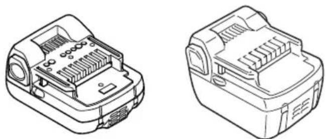
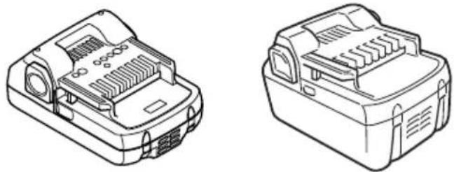
| Compatible battery | BSL18xx series and multi-volt (BSL36A18, BSL36B18) |
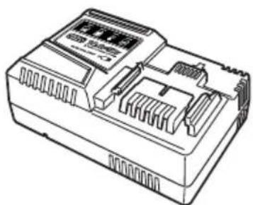
| Compatible charger | UC18YFSL or UC18YSL3 (with USB port) |
| Charging time (typical) | Approx. 20-120 min depending on battery capacity |
| No-load speed | Variable, not numerically specified |
| Tightening modes | 4 modes: Power, Normal, Soft, Self-drilling screw |
| Rotation direction | Forward/reverse (selection switch) |
| Battery charge indicator | LED residual power indicator |
| Lighting | Integrated LED, auto-off after 2 min |
| Protection | IP56 (dust-resistant and water jet-resistant, main unit with battery) |
| Safety | Thermal protection, overload, low battery; automatic stop |
| Bit attachment | 6.35 mm (1/4") hex chuck with sliding sleeve |
| Included accessories | Driver bit, belt hook, strong joint |
| Mechanism | Hydraulic impact mechanism (oil bath) for low noise |
| Operating temperature | -5°C to 40°C (tool and battery) |
| Warranty | Manufacturer's warranty according to national regulations |
| Sound level | Sound pressure 79 dB(A), sound power 90 dB(A); K=3 dB(A) |
| Vibration | Vibration emission a_h = 13.2 m/s² (impact tightening), K=1.5 m/s² |
Frequently Asked Questions - WHP18DBL HiKOKI
User questions about WHP18DBL HiKOKI
0 question about this device. Answer the ones you know or ask your own.
Ask a new question about this device
Download the instructions for your Drill in PDF format for free! Find your manual WHP18DBL - HiKOKI and take your electronic device back in hand. On this page are published all the documents necessary for the use of your device. WHP18DBL by HiKOKI.
USER MANUAL WHP18DBL HiKOKI
natural_image
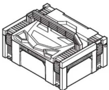
Line drawing of a handheld electric drill press device with attached strap (no text or symbols)
en Handling instructions
de Bedienungsanleitung
fr Mode d'emploi
it Istruzioni per l'uso
nl Gebruiksaanwijzing
es Instrucciones de manejo
pt Instruções de uso
sv Bruksanvisning
da Brugsanvisning
no Bruksanvisning
fi Käyttöohjeet
el Οδηγίες χειρισμού
pl Instrukcja obsługi
hu Kezelési utasítás
cs Návod k obsluze
tr Kullanım talimatları
ro Instructiuni de utilizare
① Navodila za rokovanje
sk Pokyny na manipuláciu
bg Инструкция за експлоатация
sr Uputstvo za rukovanje
hr Upute za rukovanje
1
natural_image
Diagram of a device with a gear and mechanical components, showing a directional arrow (no text or symbols present)2
3
4
natural_image
Technical drawing of a mechanical assembly with cross-section hatching (no text or labels)5
6
7
8
9
10
flowchart
graph TD
    A["SmNmPmSEm"] --> B["Signal Processing"]
    B --> C["Output"]
    D["Control Panel"] --> E["Indicator Icon S"]
    F["Input"] --> G["Arrow pointing to the Control Panel"]
11
natural_image
Line drawing of a handheld electric drill press with visible blade and handle (no text or symbols)12
natural_image
Diagram showing a mobile device connected to a wall-mounted cable, with no visible text or symbols.a
natural_image
Diagram of a mobile device connected to a wall-mounted cable, showing connections without any text or symbols.b
13
14
15
natural_image
Line drawing of a handheld power tool with a hand adjusting its tip, showing motion arrows (no text or symbols)GENERAL POWER TOOL SAFETY WARNINGS

WARNING
Read all safety warnings, instructions, illustrations and specifications provided with this power tool.
Failure to follow all instructions listed below may result in electric shock, fi re and/or serious injury.
Save all warnings and instructions for future reference.
The term “power tool” in the warnings refers to your mains-operated (corded) power tool or battery-operated (cordless) power tool.
1) Work area safety
a) Keep work area clean and well lit. Cluttered or dark areas invite accidents
b) Do not operate power tools in explosive atmospheres, such as in the presence of fl ammable liquids, gases or dust.
Power tools create sparks which may ignite the dust or fumes.
c) Keep children and bystanders away while operating a power tool.
Distractions can cause you to lose control.
2) Electrical safety
a) Power tool plugs must match the outlet. Never modify the plug in any way. Do not use any adapter plugs with earthed (grounded) power tools.
Unmodified plugs and matching outlets will reduce risk of electric shock.
b) Avoid body contact with earthed or grounded surfaces, such as pipes, radiators, ranges and refrigerators.
There is an increased risk of electric shock if your body is earthed or grounded.
c) Do not expose power tools to rain or wet conditions.
Water entering a power tool will increase the risk of electric shock.
d) Do not abuse the cord. Never use the cord for carrying, pulling or unplugging the power tool.
Keep cord away from heat, oil, sharp edges or moving parts.
Damaged or entangled cords increase the risk of electric shock.
e) When operating a power tool outdoors, use an extension cord suitable for outdoor use.
Use of a cord suitable for outdoor use reduces the risk of electric shock.
f) If operating a power tool in a damp location is unavoidable, use a residual current device (RCD) protected supply.
Use of an RCD reduces the risk of electric shock.
3) Personal safety
a) Stay alert, watch what you are doing and use common sense when operating a power tool. Do not use a power tool while you are tired or under the influence of drugs, alcohol or medication.
A moment of inattention while operating power tools may result in serious personal injury.
b) Use personal protective equipment. Always wear eye protection.
Protective equipment such as a dust mask, non-skid safety shoes, hard hat or hearing protection used for appropriate conditions will reduce personal injuries.
c) Prevent unintentional starting. Ensure the switch is in the off-position before connecting to power source and/or battery pack, picking up or carrying the tool.
Carrying power tools with your fi nger on the switch or energising power tools that have the switch on invites accidents.
d) Remove any adjusting key or wrench before turning the power tool on.
A wrench or a key left attached to a rotating part of the power tool may result in personal injury.
e) Do not overreach. Keep proper footing and balance at all times.
This enables better control of the power tool in unexpected situations.
f) Dress properly. Do not wear loose clothing or jewellery. Keep your hair and clothing away from moving parts.
Loose clothes, jewellery or long hair can be caught in moving parts.
g) If devices are provided for the connection of dust extraction and collection facilities, ensure these are connected and properly used.
Use of dust collection can reduce dust-related hazards.
h) Do not let familiarity gained from frequent use of tools allow you to become complacent and ignore tool safety principles.
A careless action can cause severe injury within a fraction of a second.
4) Power tool use and care
a) Do not force the power tool. Use the correct power tool for your application.
The correct power tool will do the job better and safer at the rate for which it was designed.
b) Do not use the power tool if the switch does not turn it on and off. Any power tool that cannot be controlled with the switch is dangerous and must be repaired.
c) Disconnect the plug from the power source and/or remove the battery pack, if detachable, from the power tool before making any adjustments, changing accessories, or storing power tools.
Such preventive safety measures reduce the risk of starting the power tool accidentally.
d) Store idle power tools out of the reach of children and do not allow persons unfamiliar with the power tool or these instructions to operate the power tool.
Power tools are dangerous in the hands of untrained users.
e) Maintain power tools and accessories. Check for misalignment or binding of moving parts, breakage of parts and any other condition that may affect the power tool's operation. If damaged, have the power tool repaired before use.
Many accidents are caused by poorly maintained power tools.
f) Keep cutting tools sharp and clean.
Properly maintained cutting tools with sharp cutting edges are less likely to bind and are easier to control.
g) Use the power tool, accessories and tool bits etc. in accordance with these instructions, taking into account the working conditions and the work to be performed.
Use of the power tool for operations different from those intended could result in a hazardous situation.
h) Keep handles and grasping surfaces dry, clean and free from oil and grease.
Slippery handles and grasping surfaces do not allow for safe handling and control of the tool in unexpected situations.
5) Battery tool use and care
a) Recharge only with the charger specified by the manufacturer.
A charger that is suitable for one type of battery pack may create a risk of fi re when used with another battery pack.
b) Use power tools only with specifically designated battery packs.
Use of any other battery packs may create a risk of injury and fire.
c) When battery pack is not in use, keep it away from other metal objects, like paper clips, coins, keys, nails, screws or other small metal objects, that can make a connection from one terminal to another.
Shorting the battery terminals together may cause burns or a fire.
d) Under abusive conditions, liquid may be ejected from the battery; avoid contact. If contact accidentally occurs, fl ush with water. If liquid contacts eyes, additionally seek medical help.
Liquid ejected from the battery may cause irritation or burns.
e) Do not use a battery pack or tool that is damaged or modified.
Damaged or modified batteries may exhibit unpredictable behaviour resulting in fire, explosion or risk of injury.
f) Do not expose a battery pack or tool to fire or excessive temperature.
Exposure to fire or temperature above 130 °C may cause explosion.
g) Follow all charging instructions and do not charge the battery pack or tool outside the temperature range specified in the instructions.
Charging improperly or at temperatures outside the specified range may damage the battery and increase the risk of fire.
6) Service
a) Have your power tool serviced by a qualified repair person using only identical replacement parts.
This will ensure that the safety of the power tool is maintained.
b) Never service damaged battery packs.
Service of battery packs should only be performed by the manufacturer or authorized service providers.
PRECAUTION
Keep children and infi rm persons away.
When not in use, tools should be stored out of reach of children and infi rm persons.
CORDLESS OIL PULSE DRIVER SAFETY WARNINGS
Hold the power tool by insulated gripping surfaces, when performing an operation where the fastener may contact hidden wiring. Fasteners contacting a "live" wire may make exposed metal parts of the power tool "live" and could give the operator an electric shock.
ADDITIONAL SAFETY WARNINGS
-
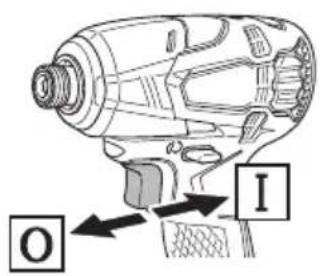
This is a portable tool for tightening and loosening screws, bolts and nuts. Use it only for these operation.
-
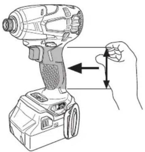
Make sure to securely hold the tool during operation. Failure to do so can result in accidents or injuries. (Fig. 15)
-
Make sure that the battery is installed firmly. If it is as all loose it could come off and cause an accident.
-
Preparing and checking the work environment. Make sure that the work site meets all the conditions laid forth in the precautions.
-
Do not allow foreign matter to enter the hole for connecting the rechargeable battery.
-
Never disassemble the rechargeable battery and charger.
-
Never short-circuit the rechargeable battery. Short-circuiting the battery will cause a great electric current and overheat. It results in burn or damage to the battery.
-
Do not dispose of the battery in fire. If the battery is burnt, it may explode.
-
Bring the battery to the shop from which it was purchased as soon as the post-charging battery life becomes too short for practical use. Do not dispose of the exhausted battery.
-
Do not insert object into the air ventilation slots of the charger. Inserting metal objects or inflammables into the charger air ventilation slots will result in electrical shock hazard or damaged charger.
-
Check the actual tightening torque with a toruge wrench.
-
Stop the tool before switching the direction of rotation. Always release the switch and wait for tool to stop before switching the direction of rotation.
-
Never touch the turning part. Do not allow the turning part section to get near your hands or any other part of your body. You could be cut or caught in the turning part. Also, be careful not to touch the turning part after using continuously it for a long time. It gets quite hot and could burn you.
-
Please use the designated attachments which are listed in the operations manual and HiKOKI's catalog. Accidents or injuries could result from not doing so.
-
Make sure to firmly install the attachments in the main shaft. If the attachments is not firmly installed it might come out and cause injuries.
After installing the driver bit, pull lightly out the driver bit to make sure that it does not come loose during use. If the guide sleeve does not return to its original position, then the driver bit is not installed properly.
-
Resting the unit after continuous work.
-
The power tool is equipped with a temperature protection circuit to protect the motor. Continuous work may cause the temperature of the unit to rise, activating the temperature protection circuit and automatically stopping operation. If this happens, allow the power tool to cool before resuming use.
-
The motor may stop in the event the tool is overloaded. In this should occur, release the tool's switch and eliminate the cause of the overload.
Avoid touching the front case which can heat up during continuous operation.
-
The use of the battery in a cold condition (below 0 degree Centigrade) can sometimes result in the weakened tightening torque and reduced amount of work. This, however, is a temporary phenomenon, and returns to normal when the battery warms up.
-
Install securely the hook. Unless the hook is securely installed, it may cause an injury while using.
When electing to carry the tool hooked to your hip belt, make sure to detach the driver bit and side handle. Failure to do so may result in unexpected injury.
- Do not touch the metal parts, as it gets very hot during continuous work.
English
- Do not look directly into the light. Such actions could result in eye injury.
Wipe off any dirt or grime attached to the lens of the LED light with a soft cloth, being careful not to scratch the lens.
Scratches on the lens of the LED light can result in decreased brightness.
- Always use the tool and battery at temperatures between -5^ and 40^ .
CAUTION ON LITHIUM-ION BATTERY
To extend the lifetime, the lithium-ion battery equips with the protection function to stop the output.
In the cases of 1 to 3 described below, when using this product, even if you are pulling the switch, the motor may stop. This is not the trouble but the result of protection function.
- When the battery power remaining runs out, the motor stops.
In such a case, charge it up immediately.
-
If the tool is overloaded, the motor may stop. In this case, release the switch of tool and eliminate causes of overloading. After that, you can use it again.
-
If the battery is overheated under overload work, the battery power may stop.
In this case, stop using the battery and let the battery cool. After that, you can use it again.
Furthermore, please heed the following warning and caution. WARNING
In order to prevent any battery leakage, heat generation, smoke emission, explosion and ignition beforehand, please be sure to heed the following precautions.
- Make sure that swarf and dust do not collect on the battery.
During work make sure that swarf and dust do not fall on the battery.
○ Make sure that any swarf and dust falling on the power tool during work do not collect on the battery.
- Do not store an unused battery in a location exposed to swarf and dust.
Before storing a battery, remove any swarf and dust that may adhere to it and do not store it together with metal parts (screws, nails, etc.).
-
Do not pierce battery with a sharp object such as a nail, strike with a hammer, step on, throw or subject the battery to severe physical shock.
-
Do not use an apparently damaged or deformed battery.
-
Do not use the battery in reverse polarity.
-
Do not connect directly to an electrical outlets or car cigarette lighter sockets.
-
Do not use the battery for a purpose other than those specified.
-
If the battery charging fails to complete even when a specified recharging time has elapsed, immediately stop further recharging.
-
Do not put or subject the battery to high temperatures or high pressure such as into a microwave oven, dryer, or high pressure container.
-
Keep away from fi re immediately when leakage or foul odor are detected.
-
Do not use in a location where strong static electricity generates.
-
If there is battery leakage, foul odor, heat generated, discolored or deformed, or in any way appears abnormal during use, recharging or storage, immediately remove it from the equipment or battery charger, and stop use.
-
Do not immerse the battery or allow any fluids to flow inside. Conductive liquid ingress, such as water, can cause damage resulting in fire or explosion. Store your battery in a cool, dry place, away from combustible and fl ammable items. Corrosive gas atmospheres must be avoided.
CAUTION
- If liquid leaking from the battery gets into your eyes, D do not rub your eyes and wash them well with fresh clean water such as tap water and contact a doctor immediately.
If left untreated, the liquid may cause eye-problems.
- If liquid leaks onto your skin or clothes, wash well with clean water such as tap water immediately.
There is a possibility that this can cause skin irritation.
- If you find rust, foul odor, overheating, discolor, deformation, and/or other irregularities when using the battery for the first time, do not use and return it to your supplier or vendor.
WARNING
If a conductive foreign matter enters in the terminal of lithium ion battery, the battery may be shorted, causing fire. When storing the lithium ion battery, obey surely the rules of following contents.
○ Do not place conductive debris, nail and wires such as iron wire and copper wire in the storage case.
To prevent shorting from occurring, load the battery in the tool or insert securely the battery cover for storing until the ventilator is not seen.
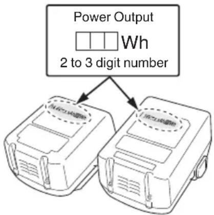
REGARDING LITHIUM-ION BATTERY TRANSPORTATION
When transporting a lithium-ion battery, please observe the following precautions.
WARNING
Notify the transporting company that a package contains a lithium-ion battery, inform the company of its power output and follow the instructions of the transportation company when arranging transport.
○ Lithium-ion batteries that exceed a power output of 100 Wh are considered to be in the freight classification of Dangerous Goods and will require special application procedures.
☐ For transportation abroad, you must comply with international law and the rules and regulations of the destination country.
flowchart
graph TD
    A["Power Output"] --> B["Device 1: Wh"]
    A --> C["Device 2: Wh"]
    B --> D["2 to 3 digit number"]
    C --> D
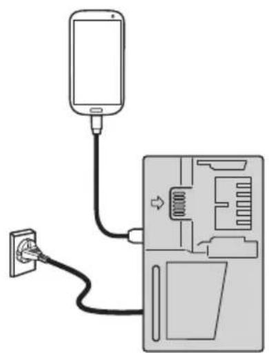
USB DEVICE CONNECTION PRECAUTIONS (ONLY WITH UC18YSL3 CHARGER)
When an unexpected problem occurs, the data in a USB device connected to this product may be corrupted or lost. Always make sure to back up any data contained in the USB device prior to use with this product.
Please be aware that our company accepts absolutely no responsibility for any data stored in a USB device that is corrupted or lost, nor for any damage that may occur to a connected device.
WARNING
- Prior to use, check the connecting USB cable for any defect or damage.
Using a defective or damaged USB cable can cause smoke emission or ignition. - When the product is not being used, cover the USB port with the rubber cover.
Buildup of dust etc. in the USB port can cause smoke emission or ignition.
NOTE
- There may be an occasional pause during USB recharging.
When a USB device is not being charged, remove the USB device from the charger.
Failure to do so may not only reduce the battery life of a USB device, but may also result in unexpected accidents. - It may not be possible to charge some USB devices, depending on the type of device.
PRECAUTIONS REGARDING THE DUST-RESISTANCE AND WATER-PROOFING FUNCTIONS
This product conforms to IP56 protection class ratings (dust-resistance and water-proofing) for electrical equipment as stipulated by the international IEC regulations. (Only the main unit conforms to the IP56 protection class ratings when equipped with a battery.)
[Descriptions of IP Codes]
IP56

Protection rating for water penetration
Must be no adverse effects on the equipment when sprayed with powerful jets of water from all directions (water-proofed).
(100 L of water per minute sprayed for approximately three minutes from a distance of approximately three meters with the use of a spray nozzle with a diameter of 12.5 mm.)
Protection rating for external assault by solid objects
Dust that may cause adverse effects on the equipment must not be able to enter (dust-resistance).
(The equipment to be left non-operable in a test chamber in which particles of talcum powder with a diameter of less than 75 m are floating in the air with the use of an agitation pump at a rate of 2 kg per cubic meter for eight hours.)
The equipment has been designed to withstand the effects of dust and water, but there is no guarantee that it will not malfunction. Do not use or leave the equipment in locations where it is subject to excessive amounts of dust, or in locations where it is submerged in water or subject to rainwater.
SYMBOLS
WARNING
The following show symbols used for the machine. Be sure that you understand their meaning before use.
| WHP18DBL: Cordless Oil Pulse Driver | |
| To reduce the risk of injury, user must read instruction manual. | |
| Only for EU countriesDo not dispose of electric tools together with household waste material!In observance of European Directive 2012/19/EU on waste electrical and electronic equipment and its implementation in accordance with national law, electric tools that have reached the end of their life must be collected separately and returned to an environmentally compatible recycling facility. | |
| Direct current | |
| V Rated voltage | |
| n_0 | No-load speed |
| min-1 | Oscillation per minute |
| Pm Power mode | |
| Nm Normal mode | |
| Sm Soft mode | |
| SEm Self drilling screw mode | |
| Bpm Impact rate | |
| Small screw | |
| Ordinary bolt | |
| Self drilling screw | |
| MT Tightening torque (Maximum) | |
| Hex. drive size | |
| Weight* (According to EPTA-Procedure 01/2014) | |
| Switching ON | |
| Switching OFF | |
| Disconnect the battery | |
| Light section switch | |
| Always ON (turn off after 2 minute) | |
| Light only SW-ON | |
English
| Always OFF | |
| Clockwise rotation | |
| Counterclockwise rotation | |
| Battery capacity | |
| Remaining battery indicator switch | |
| The battery remaining power is nearly empty. Recharge the battery soonest possible | |
| The battery remaining power is a half. | |
| The battery remaining power is enough. | |
| Tightening mode selector switch | |
| Tightening mode indicator lamp | |
| “Delicate work” Tightening small diameter screws (M6 or similar), etc. | |
| “Normal work” Tightening short screws, Affi xing plasterboard, etc. | |
| “Normal work” Tightening long screws, coach screws, bolts, etc. | |
| Self drilling screw tightening | |
| Warning |
* Depending on attached battery. The heaviest weight is measured with BSL36B18 (sold separately).
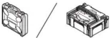
STANDARD ACCESSORIES
In addition to the main unit (1 unit), the package contains the accessories listed on page 259.
Standard accessories are subject to change without notice.
APPLICATIONS
Driving and removing of machine screws, wood screws, tapping screws, etc.
SPECIFICATIONS
The specifications of this machine are listed in the Table on page 259.
NOTE
Due to HiKOKI's continuing program of research and development, the specifications herein are subject to change without prior notice.
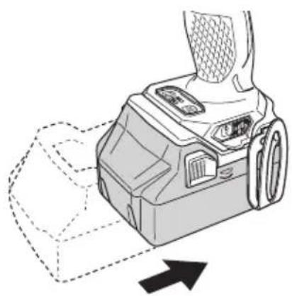
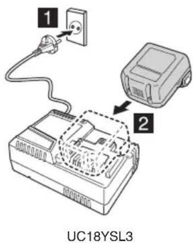
CHARGING
Before using the power tool, charge the battery as follows.
- Connect the charger's power cord to the receptacle.
When connecting the plug of the charger to a receptacle, the pilot lamp will blink in red (At 1-second intervals).
- Insert the battery into the charger.
Firmly insert the battery into the charger as shown in Fig. 2 (on page 2).
- Charging
When inserting a battery in the charger, charging will commence and the pilot lamp will light continuously in red.
When the battery becomes fully recharged, the pilot lamp will blink in red. (At 1-second intervals) (See Table 1)
● Pilot lamp indication
The indications of the pilot lamp will be as shown in Table 1, according to the condition of the charger or the rechargeable battery.
Table 1
| Indications of the pilot lamp | ||||
| Pilot lamp(red) | Before charging | Blinks | Lights for 0.5 seconds. Does not light for 0.5 seconds. (off for 0.5 seconds) | |
| While charging Lights | Lights continuously | |||
| Charging complete | Blinks | Lights for 0.5 seconds. Does not light for 0.5 seconds. (off for 0.5 seconds) | ||
| Overheat standby | Blinks | Lights for 1 second. Does not light for 0.5 seconds. (off for 0.5 seconds) | Battery overheated. Unable to charge. (Charging will commence when battery cools) | |
| Charging impossible | Flickers | Lights for 0.1 seconds. Does not light for 0.1 seconds. (off for 0.1 seconds) | Malfunction in the battery or the charger | |
● Regarding the temperatures and charging time of the battery. The temperatures and charging time will become as shown in Table 2.
Table 2
| Charger | UC18YFSL | ||||||
| Battery | Type of battery Li-ion | ||||||
| Temperatures at which the battery can be recharged | 0°C - 50°C | ||||||
| Charging voltage V | 14.4 18 | ||||||
| Charging time, approx. (At 20°C) | BSL14xx series BSL18xx series | Multi volt series | |||||
| (4 cells) (8 cells) (5 cells) (10 cells) (10 cells) | |||||||
| min. | BSL1415S:20BSL1415:22BSL1415X:22BSL1420:30BSL1425:35BSL1430C:45 | BSL1430:45BSL1440:60BSL1450:75BSL1460:90 | BSL1815S:20BSL1815:22BSL1815X:22BSL1820:30BSL1825:35BSL1830C:45BSL1850C:75 | BSL1830:45BSL1840:60BSL1850:75BSL1860:90 | |||
NOTE
The recharging time may vary according to temperature and power source voltage.
CAUTION
When the battery charger has been continuously used, the battery charger will be heated, thus constituting the cause of the failures. Once the charging has been completed, give 15 minutes rest until the next charging.
4. Disconnect the charger's power cord from the receptacle.
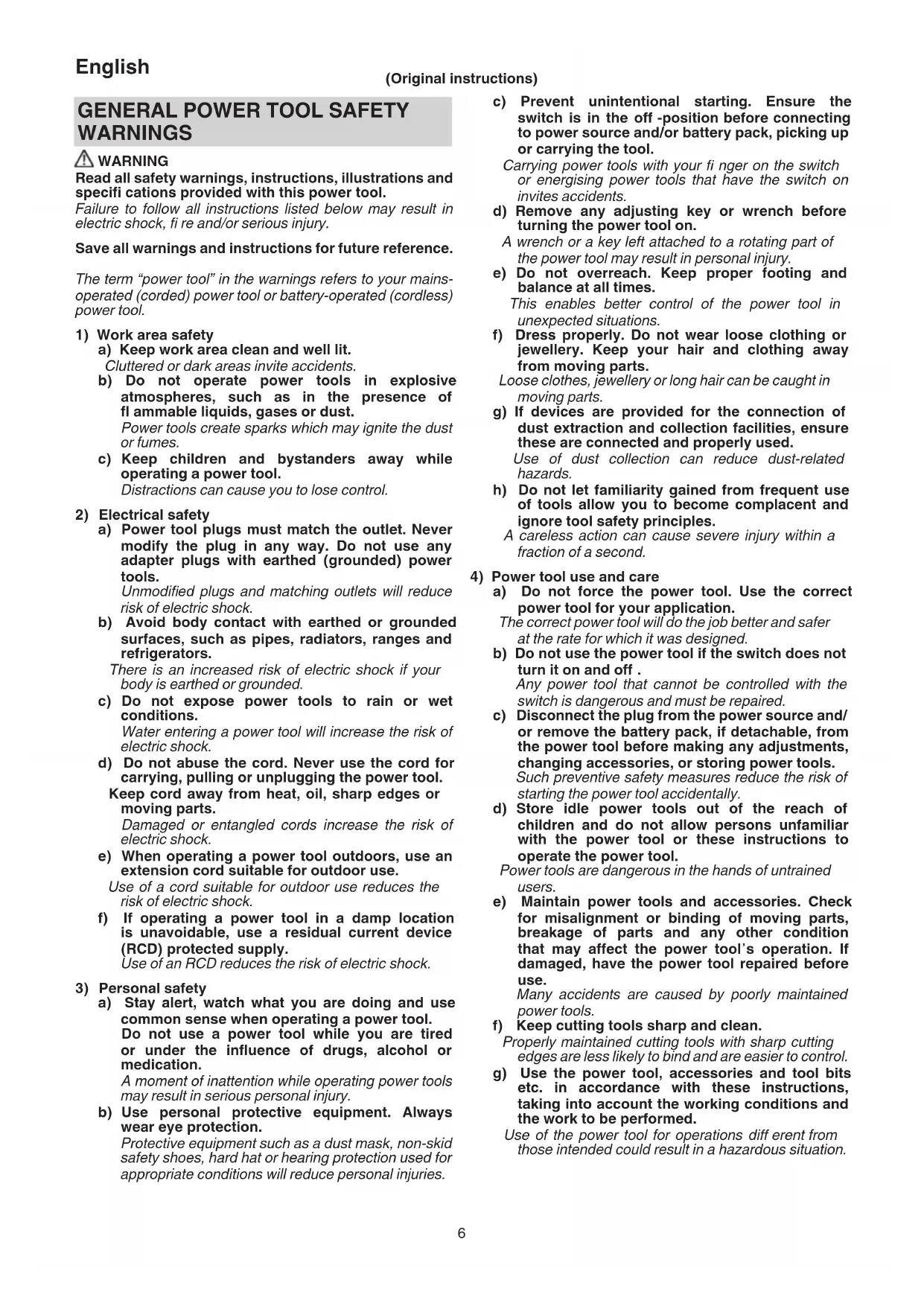
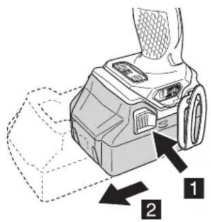
5. Hold the charger firmly and pull out the battery.
NOTE
Be sure to pull out the battery from the charger after use, and then keep it.
CAUTION
☐ If the battery is charged while it is heated because it has been left for a long time in a location subject to direct sunlight or because the battery has just been used, the pilot lamp of the charger lights for 1 second, does not light for 0.5 seconds (off for 0.5 seconds). In such a case, first let the battery cool, then start charging.
When the pilot lamp flickers (at 0.2-second intervals), check for and take out any foreign objects in the charger's battery connector. If there are no foreign objects, it is probable that the battery or charger is malfunctioning. Take it to your authorized Service Center.
○ Since the built-in micro computer takes about 3 seconds to confirm that the battery being charged with charger is taken out, wait for a minimum of 3 seconds before reinserting it to continue charging. If the battery is reinserted within 3 seconds, the battery may not be properly charged.
☐ If the pilot lamp does not blink in red (every second) even though the charger cord is connected to the power, it indicates that the protection circuit of the charger may be activated.
Remove the cord or plug from the power and then connect it again after 30 seconds or so. If this does not cause the pilot lamp to blink in red (every second), please take the charger to the HiKOKI Authorized Service Center.
6. Charging
When inserting a battery in the charger, the charge indicator lamp will blink in blue.
When the battery becomes fully recharged, the charge indicator lamp will light up in green. (See Table 3)
(1) Charge indicator lamp indication
The indications of the charge indicator lamp will be as shown in Table 3, according to the condition of the charger or the rechargeable battery.
Table 3
| Indications of the charge indicator lamp | ||||
| Charge indicator lamp (RED / BLUE / GREEN / PURPLE) | Before charging | Blinks (RED) | Lights for 0.5 seconds. Does not light for 0.5 seconds. (off for 0.5 seconds) | Plugged into power source |
| While charging | Blinks (BLUE) | Lights for 0.5 seconds. Does not light for 1 second. (off for 1 second) | Battery capacity at less than 50% | |
| Blinks (BLUE) | Lights for 1 second. Does not light for 0.5 seconds. (off for 0.5 seconds) | Battery capacity at less than 80% | ||
| Lights (BLUE) | Lights continuously | Battery capacity at more than 80% | ||
| Charging complete | Lights (GREEN) | Lights continuously(Continuous buzzer sound: about 6 seconds) | ||
| Overheat standby | Blinks (RED) | Lights for 0.3 seconds. Does not light for 0.3 seconds. (off for 0.3 seconds) | Battery overheated. Unable to charge. (Charging will commence when battery cools) | |
| Charging impossible | Flickers (PURPLE) | Lights for 0.1 seconds. Does not light for 0.1 seconds. (off for 0.1 seconds)(Intermittent buzzer sound: about 2 seconds) | Malfunction in the battery or the charger | |
(2) Regarding the temperatures and charging time of the rechargeable battery
The temperatures and charging time will become as shown in Table 4.
Table 4
| Charger | UC18YSL3 | ||||||
| Battery | Type of battery Li-ion | ||||||
| Temperatures at which the battery can be recharged | 0°C - 50°C | ||||||
| Charging voltage V | 14.4 18 | ||||||
| Charging time, approx. (At 20°C) | BSL14xx series BSL18xx series | Multi volt series | |||||
| (4 cells) (8 cells) (5 cells) (10 cells) (10 cells) | |||||||
| min. | BSL1415S: 15BSL1415 : 15BSL1415X: 15BSL1420 : 20BSL1425 : 25BSL1430C: 30 | BSL1430 : 20BSL1440 : 26BSL1450 : 32BSL1460 : 38 | BSL1815S: 15BSL1815 : 15BSL1815X: 15BSL1820 : 20BSL1825 : 25BSL1830C: 30BSL1850C: 32 | BSL1830 : 20BSL1840 : 26BSL1850 : 32BSL1860 : 38 | |||
| USB | Charging voltage V | 5 | |||||
| Charging current A | 2 | ||||||
NOTE
The recharging time may vary according to the ambient temperature and power source voltage.
-
Disconnect the charger's power cord from the receptacle.
-
Hold the charger firmly and pull out the battery.
NOTE
Be sure to pull out the battery from the charger after use, and then keep it.
Regarding electric discharge in case of new batteries, etc.
As the internal chemical substance of new batteries and batteries that have not been used for an extended period is not activated, the electric discharge might be low when
using them the first and second time. This is a temporary phenomenon, and normal time required for recharging will be restored by recharging the batteries 2 – 3 times.
How to make the batteries perform longer.
(1) Recharge the batteries before they become completely exhausted.
When you feel that the power of the tool becomes weaker, stop using the tool and recharge its battery. If you continue to use the tool and exhaust the electric current, the battery may be damaged and its life will become shorter.
(2) Avoid recharging at high temperatures.
A rechargeable battery will be hot immediately after use. If such a battery is recharged immediately after use, its internal chemical substance will deteriorate, and the battery life will be shortened. Leave the battery and recharge it after it has cooled for a while.
CAUTION
☐ If the battery is charged while it is heated because it has been left for a long time in a location subject to direct sunlight or because the battery has just been used, the charge indicator lamp of the charger lights for 0.3 seconds, does not light for 0.3 seconds (off for 0.3 seconds). In such a case, first let the battery cool, then start charging.
When the charge indicator lamp flickers (at 0.2-second intervals), check for and take out any foreign objects in the charger's battery connector. If there are no foreign objects, it is probable that the battery or charger is malfunctioning. Take it to your authorized Service Center.
○ Since the built-in micro computer takes about 3 seconds to confirm that the battery being charged with UC18YSL3 is taken out, wait for a minimum of 3 seconds before reinserting it to continue charging. If the battery is reinserted within 3 seconds, the battery may not be properly charged.
MOUNTING AND OPERATION
| Action Figure Page | ||
| Removing and inserting the battery 1 2 | ||
| Charging 2 2 | ||
| Mounting the driver bit 3 2 | ||
| Bit piece built in at the bottom of the hexagonal hole of the main shaft. | 4 | 2 |
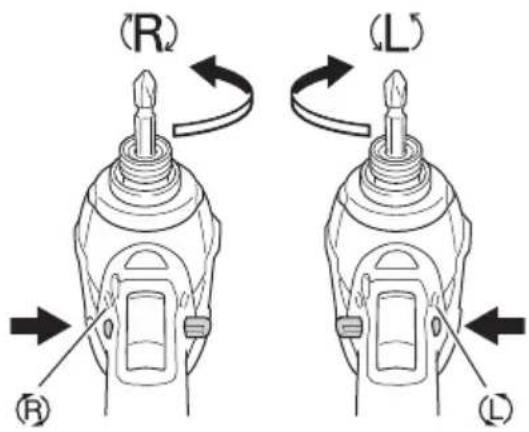
| Reversing the rotational direction 5 3 | ||
| Switch operation 6 3 | ||
| Removing and mounting the hook 7 3 | ||
| Remaining battery indicator | 8 3 | |
| How to use the LED light*1 | 9 | 3 |
| Tightening mode selector function*2 | 10 | 3 |
| LED light warning signals | 11 | 4 |
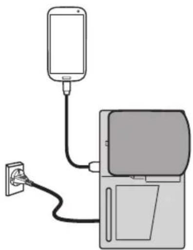
| Charging a USB device from a electrical outlet | 12-a | 4 |
| Charging a USB device and battery from a electrical outlet | 12-b | 4 |
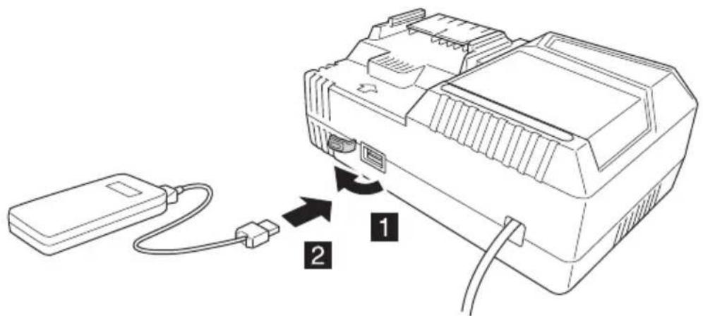
| How to recharge USB device | 13 | 4 |
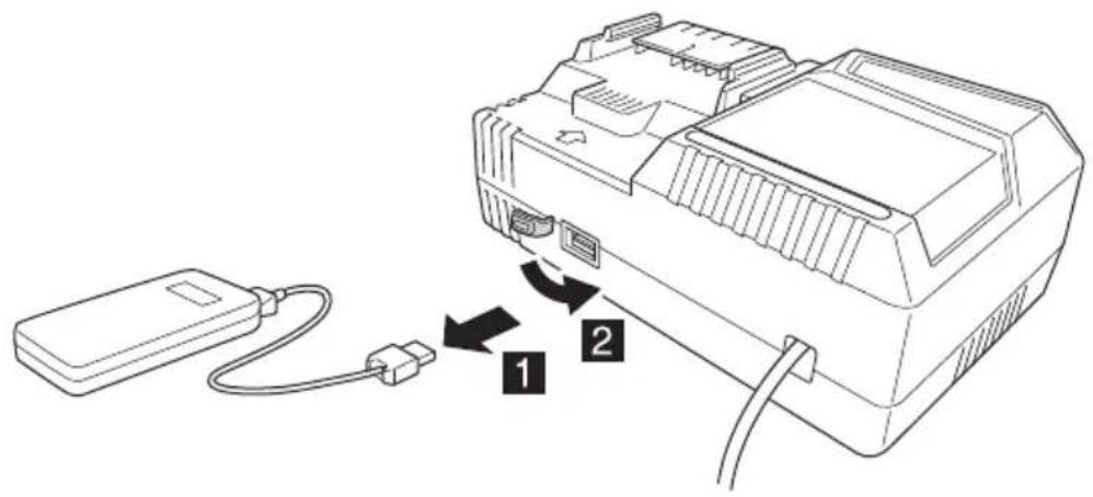
| When charging of USB device is completed | 14 | 5 |
| Selecting accessories — 260 |
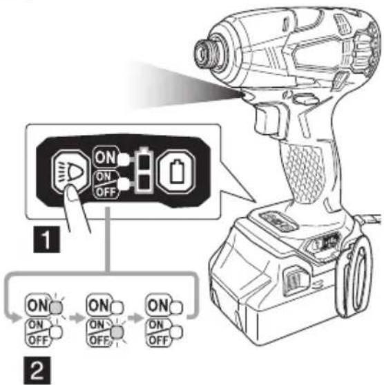
*1 How to use the LED light
NOTE
To prevent the battery power consumption caused by forgetting to turn off the LED light, the light goes off automatically in about 2 minutes.
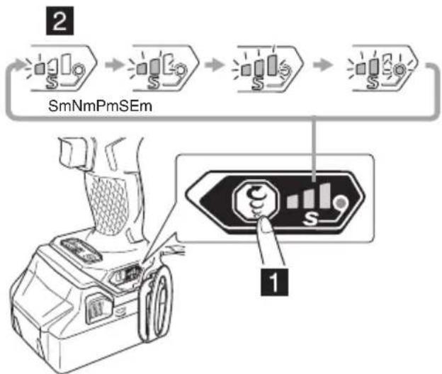
*2 Tightening mode selector function
CAUTION
Select tightening mode while the trigger switch is released. Failure to do so could result in malfunction.
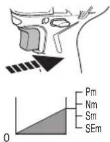
By using the Tightening mode selector switch on the side of the tool body, the tightening torque can be adjusted according to the type of work.
The Tightening mode switches between 4 different modes each time the Tightening mode selector switch is pressed. Normal mode allows screws to be tightened smoothly and gently.
Under normal circumstances, use Normal mode.
Power mode is suitable for normal work that requires more force, such as tightening long screws.
Use it when you feel that Normal mode lacks sufficient power.
Self-drilling screw mode is used for tightening self-drilling Teks screws. This mode reduces the chances of overtightening that could result in severing of the screw head, breakage of the screw, or slippage.
NOTE
☐ The appropriate mode differs depending on the screw and the material being screwed. Drive in a few test screws and adjust the mode setting accordingly.
☐ The tightening mode selector switch can only be set after the battery has been installed in the driver and the trigger switch has been pulled once.
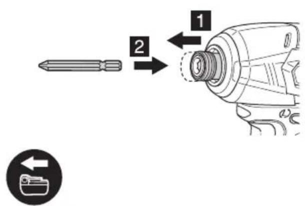
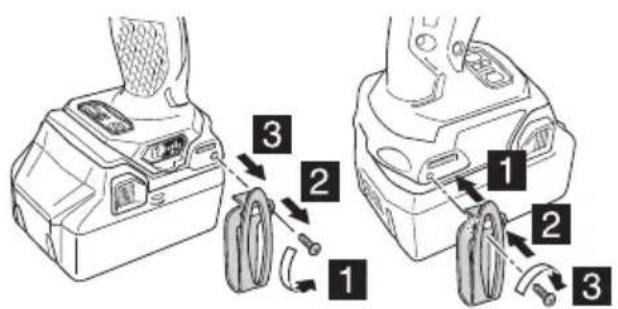
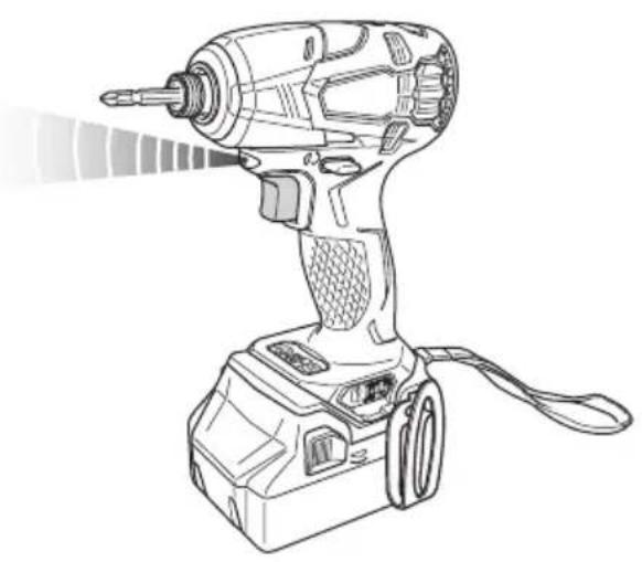
1. Installing the driver bit
Always follow the following procedure to install driver bit. (Fig. 3)
(1) Pull the guide sleeve away from front of the tool.
(2) Insert the driver bit into the hexagonal hole in the main shaft.
(3) Release the guide sleeve and it returns to its original position.
CAUTION
☐ If the guide sleeve does not return to its original position, then the driver bit is not installed properly.
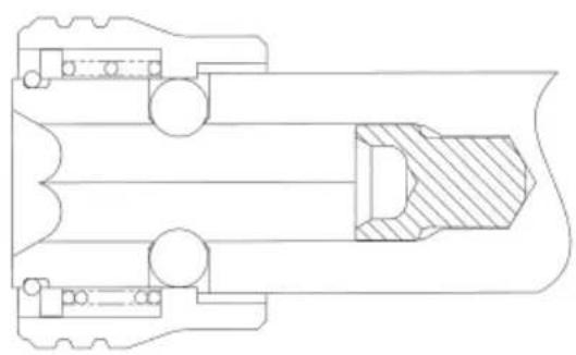
☐ This product also comes equipped with a bit piece. Make sure that the bit piece is inside of the hexagonal hole in the main shaft, then install the driver bit. (Fig. 4)
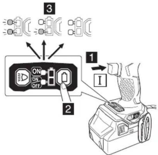
LED LIGHT WARNING SIGNALS
This product features functions that are designed to protect the tool itself as well as the battery. While the switch is pulled, if any of the safeguard functions activate during operation, the LED light will blink as described in Table 5, Fig.11.
When any of the safeguard functions are triggered, immediately remove your finger from the switch and follow the instructions described under corrective action.
Table 5
| Safeguard Function | LED Light Display | Corrective Action |
| Overload | On 0.5 second/off 0.5 second(Flashes slowly) | If you are working in a cold environment, carry out light load work such as tightening screws to warm the tool up, or let the tool stand in a room or other warm location for an appropriate period of time before using it. |
| Overtemperature | On 0.1 second/off 0.1 second(Flashes quickly) | Cool the tool down sufficiently, or wait until it cools down sufficiently. |
FEATURES OF THE CORDLESS OIL PULSE DRIVER
The oil pulse driver uses a viscous oil to generate pressure that rotates the driver bit. This mechanism reduces the noises associated with tightening screws to levels that are considerably lower than those of noises generated by other types of impact drivers.
NOTE
The viscosity of the oil changes depending on temperature. Note the following when using the tool:
☐ Do not use the tool in an environment below -5^ , or when it has been left to stand for a prolonged period of time in an environment below -5^ .
Otherwise, impacts (torque) may not be generated although the switch is pulled, or the number of impacts that are generated may reduce signifi cantly, which may overload the tool, and as a result, the motor may fail.
☐ If the tool is very hot after it has been continuously used for a certain period of time, continuing the work may make it difficult to tighten screws as the tool in this condition may not be able to generate a sufficient amount of torque. In this case, turn off the switch and do not use the tool for 30 minutes or more.
This product utilizes a hydraulic impacting mechanism. This means that the protective function incorporated in the lithium ion battery may not work when the viscosity of the oil is within a certain range, which may cause the motor to fail.
Do not use the product in a cold environment (-5°C or less) or continuously under conditions in which the product may be overloaded.
MAINTENANCE AND INSPECTION
1. Inspecting the driver bit
Using a broken driver bit or one with a worn out tip is dangerous because the driver bit can slip. Replace it.
2. Inspecting the mounting screws
Regularly inspect all mounting screws and ensure that they are properly tightened. Should any of the screws be loose, retighten them immediately. Failure to do so could result in serious hazard.
3. Maintenance of the motor
The motor unit winding is the very “heart” of the power tool. Exercise due care to ensure the winding does not become damaged and/or wet with oil or water.
4. Cleaning on the outside
When the power tool is stained, wipe with a soft dry cloth or a cloth moistened with soapy water. Do not use chloric solvents, gasoline or paint thinner, for they melt plastics.
5. Storage
Store the power tool in a place in which the temperature is less than 40^ C and out of reach of children.
NOTE
Storing lithium-ion batteries.
Make sure the lithium-ion batteries have been fully charged before storing them.
Prolonged storage (3 months or more) of batteries with a low charge may result in performance deterioration, signifi cantly reducing battery usage time or rendering the batteries incapable of holding a charge.
However, signifi cantly reduced battery usage time ma be recovered by repeatedly charging and using the batteries two to fi ve times.
If the battery usage time is extremely short despite repeated charging and use, consider the batteries dead and purchase new batteries.
CAUTION
In the operation and maintenance of power tools, the safety regulations and standards prescribed in each country must be observed.
Important notice on the batteries for the HiKOKI cordless power tools
Please always use one of our designated genuine batteries. We cannot guarantee the safety and performance of our cordless power tool when used with batteries other than these designated by us, or when the battery is disassembled and modified (such as disassembly and replacement of cells or other internal parts).
GUARANTEE
We guarantee HiKOKI Power Tools in accordance with statutory/country specific regulation. This guarantee does not cover defects or damage due to misuse, abuse, or normal wear and tear. In case of complaint, please send the Power Tool, undismantled, with the GUARANTEE CERTIFICATE found at the end of this Handling instruction, to a HiKOKI Authorized Service Center.
Information concerning airborne noise and vibration
The measured values were determined according to EN62841 and declared in accordance with ISO 4871.
Measured A-weighted sound power level: 90 dB (A) Measured A-weighted sound pressure level: 79 dB (A) Uncertainty K: 3 dB (A).
Wear hearing protection.
Vibration total values (triax vector sum) determined according to EN62841.
Impact tightening of fasteners of the maximum capacity of the tool:
Vibration emission value a_h = 13.2 m/s^2
Uncertainty K = 1.5 m/s²
The declared vibration total value has been measured in accordance with a standard test method and may be used for comparing one tool with another.
It may also be used in a preliminary assessment of exposure.
WARNING
☐ The vibration emission during actual use of the power tool can differ from the declared total value depending in the ways in which the tool is used.
- Identify safety measures to protect the operator that are based on an estimation of exposure in the actual conditions of use (taking account of all parts of the operating cycle such as the times when the tool is switched off and when it is running idle in addition to the trigger time).
NOTE
Due to HiKOKI's continuing program of research and development, the specifications herein are subject to change without prior notice.
TROUBLESHOOTING
Use the inspections in the table below if the tool does not operate normally. If this does not remedy the problem, consult your dealer or the HiKOKI Authorized Service Center.
| Symptom Possible cause Remedy | ||
| Tool doesn't run No remaining battery power Charge the battery. | ||
| The trigger switch was held down while the battery was inserted. | ||
| Tool suddenly stopped The tool was overloaded because the oil became more viscous due to a cold environment. | Let the tool stand in a room or other warm location for an appropriate period of time before using it. | |
| The tool is overheated. Let the tool cool down. | ||
| The battery is overheated. Let the battery cool down. | ||
| The trigger switch was held down for 5 minutes or more. | ||
| Driver bits -can't be attached -fall off | The shape of the attachment portion doesn't match | Use a driver bit with a hexagonal shaft that has a width across fl ats of 6.35 mm. |
| If you are using an L-type driver bit, replace it with an S-type driver bit. | ||
| Switch can't be pulled Forward/reverse selector button is positioned halfway | Press the button firmly into position for the desired direction of rotation. | |
| An abnormal high-pitched noise occurs when the trigger switch is pulled. | The trigger switch is being pulled only slightly. | This is not a malfunction. It does not occur if the trigger switch is pulled more fully. |
| Screw head slips or comes loose. | Driver bit number doesn't match with the screw size | Install a suitable driver bit. |
| The driver bit is worn Replace with a new driver bit. | ||
| The pilot lamp is rapidly fl ickers red, and battery charging doesn't begin.The charge indicator lamp is rapidly fl ickers purple, and battery charging doesn't begin. | The battery is not inserted all the way. | Insert the battery firmly. |
| There is foreign matter in the battery terminal or where the battery is attached. | Remove the foreign matter. | |
| The pilot lamp blinks red, and battery charging doesn't begin.The charge indicator lamp blinks red, and battery charging doesn't begin. | The battery is not inserted all the way. | Insert the battery firmly. |
| The battery is overheated. If left alone, the battery will automatically begin charging if its temperature decreases, but this may reduce battery life. It is recommended that the battery be cooled in a well-ventilated location away from direct sunlight before charging it. | ||
| Battery usage time is short even though the battery is fully charged. | The battery's life is depleted. Replace the battery with a new one. | |
| The battery takes a long time to charge. | The temperature of the battery, the charger, or the surrounding environment is extremely low. | Charge the battery indoors or in another warmer environment. |
| The charger's vents are blocked, causing its internal components to overheat. | Avoid blocking the vents. | |
| The cooling fan is not running. Contact a HiKOKI Authorized Service Center for repairs. | ||
English
| Symptom Possible | cause Remedy | |
| Charging of a USB device pauses midway. | The charger was plugged into an electrical socket while the USB device was being charged using the battery as the power source. | This is not a malfunction.The charger pauses USB charging for about 5 seconds when it is differentiating between power sources. |
| A battery was inserted into the charger while the USB device was being charged using a power socket as the power source. | ||
| Charging of the USB device pauses midway when the battery and the USB device are being charged at the same time. | The battery has become fully charged. This is | not a malfunction.The charger pauses USB charging for about 5 seconds while it checks whether the battery has successfully completed charging. |
| Charging of the USB device doesn’t start when the battery and the USB device are being charged at the same time. | The remaining battery capacity is extremely low. | This is not a malfunction.When the battery capacity reaches a certain level, USB charging automatically begins. |
ALLGEMEINE
VEILIGHEIDSWAARSCHUWINGEN
WAARSCHUWINGSSIGNALEN LED-LAMPJE
● Pilot lysindikation
VEDLIKEHOLD OG INSPEKSJON
1. Inspisere driverbiten
Bruk av en ødelagt driverbit eller en driverbit med slitt tupp er farlig ettersom driverbiten kan skli. Bytt den.
2. Inspisere monteringsskruene
| WHP18DBL | ||
| (NN) | ||
 UC18YFSL UC18YSL3 UC18YFSL UC18YSL3 | 1- | |
 BSL1850 BSL1860 BSL1850 BSL1860 | 2- | |
 | 1- | |
 | 1- | |
natural_image
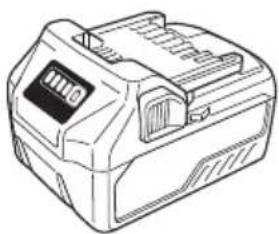
Technical line drawings of two electronic device enclosures (no text or symbols)BSL14..
natural_image
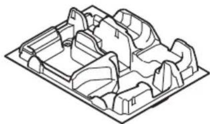
Isometric line drawing of a mechanical component with multiple circular cutouts (no text or symbols)337852
natural_image
Technical line drawings of two electronic device enclosures (no text or symbols)BSL18..
natural_image
Technical line drawing of a mechanical housing or enclosure with internal components (no text or symbols)336471
natural_image
Line drawing of a portable electronic device with control panel and display (no text or symbols)BSL36..18
natural_image
Isometric line drawing of a mechanical component or housing (no text or symbols)336475
natural_image
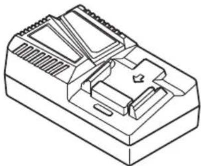
Isometric line drawing of a mechanical device housing with internal components (no text or symbols)UC18YFSL (14,4V - 18V)
natural_image
Technical line drawing of a mechanical component or housing (no text or symbols)339776
natural_image
Line drawing of a battery pack with no visible text or symbolsUC18YSL3 (14,4V - 18V)
329897
| English Dansk Română | ||||
| GUARANTEE CERTIFICATE1 Model No.2 Serial No.3 Date of Purchase4 Customer Name and Address5 Dealer Name and Address(Please stamp dealer name and address) | GARANTIBEVIS1 Modelnummer2 Serienummer3 Købsdato4 Kundes navn og adresse5 Forhandlers navn og adresse(Indsæt stempel med forhandlers navn og adresse) | CERTIFICAT DE GARANTIE1 Model nr.2 Nr. de serie3 Data cumpäräri4 Numele și adresa clientului5 Numele și adresa distribuitorului(Vå rugårn aplicați štampila cu numele și adresa distribuitorului) | ||
| Deutsch Norsk Slovenščina | ||||
| GARANTIESCHEIN1 Modell-Nr.2 Serion-Nr.3 Kaufdatum4 Name und Anschrift des Kunden5 Name und Anschrift des Händlers(Bitte mit Namen und Anschrift des Handlers abstempeln) | GARANTISERTIFIKAT1 Modellnr.2 Serionr.3 Kjøpsdato4 Kundens navn og adresse5 Forhandlerens navn og adresse(Vennligst stemple forhandlerens navn og adresse) | GARANCIJSKO POTRDILO1 Št. modela2 Serijska št.3 Datum nakupa4 Ime in naslov kupca5 Ime in naslov prodajalca(Prosimo vtisnite žig z imenom in naslovom prodajalca) | ||
| Français Suomi Slovenčina | ||||
| CERTIFICAT DE GARANTIE1 No. de modèle2 No de série3 Date d'achat4 Nom et adresse du client5 Nom et adresse du revendeur(Cachet portant le nom et l'adresse du revendeur) | TAKUUTODISTUS1 Malli nro2 Sarja nro3 Ostopāivāmāärā4 Asiakkaan nimi ja osoite5 Myyjān nimi ja osoite(Leimaa myyjān nimi ja osoite) | ZÁRUČNÝ LISTA1 Č. modelu2 Sériové č.3 Dátum zakúpenia4 Meno a adresa zákazníka5 Názov a adresa predajcu(Pečiatka s názvom a adresou predajcu) | ||
| Italiano Ελληνικά Български | ||||
| CERTIFICATO DI GARANZIA1 Modello2 N° di serie3 Data di acquisto4 Nome e indirizzo dell'acquirente5 Nome e indirizzo del rivenditore(Si prega di apporre il timbro con questi dati) | ПІЗТОПОІНТИКО ЕГГУНЄНЄ1 Ap. Movtélou2 Aúξων Ap.3 Нμερομηνία αγοράς4 ́Овома кαι δεύθυνση πελάτη5 ́Овома кαι δεύθυνση μεταπωλητή(Παρακαλούμε να χρησιμοποιηθεί σφραγίδα) | ГАРАНЦИОНЕН СЕРТИФИКАТ1 Модел No2 Сериен No3 Дата за закупуване4 Име и адрес на клиента5 Име и адрес на търговеца(Моля, отпечатайте името и адрес на дилъра) | ||
| Nederlands Polski Srpski | ||||
| GARANTIEBEWIJS1 Modelnummer2 Serienummer3 Datum van aankoop4 Naam en adres van de gebruiker5 Naam en adres van de handelaar(Stempel a.u.b. naam en adres vande de handelaar) | GWARANCJA1 Model2 Numer seryjny3 Data zakupu4 Nazwa klienta i adres5 Nazwa dealera i adres(Pieczęć punktu sprzedaży) | GARANTNI SERTIFIKAT1 Br. modela.2 Serijski br.3 Datum kupovine4 Ime i adresa kupca5 Ime i adresa prodavca(Molimo da stavite pečat na ime i adresu trgovca) | ||
| Español | CERTIFICADO DE GARANTÍA1 Número de modelo2 Número de serie3 Fecha de adquisición4 Nombre y dirección del cliente5 Nombre y dirección del distribuidor(Se ruega poner el sello del distribuidor con su nombre y dirección) | Magyar | Hrvatski | |
| GARANCIA BIZONYLAT1 Típusszám2 Sorozatszám3 A vásárlás dátuma4 A Vásárló neve és címe5 A Kereskedő neve és címe(Kérjük ide elhelyezni a Kereskedő nevének és címěnek pecsétjtét) | JAMSTVENI CERTIFIKAT1 Br modela.2 Serijski br.3 Datum kupnje4 Ime i adresa kupca5 Ime i adresa trgovca(Molimo stavite pečat na ime i adresu trgovca) | |||
| Português Čeština | ||||
| CERTIFICADO DE GARANTIA1 Número do modelo2 Número do série3 Data de compra4 Nome e morada do cliente5 Nome e morada do distribuidor(Por favor, carímbe o nome e morada do distribuidor) | ZÁRUČNÍ LIST1 Model č.2 Série č.3 Datum nákupu4 Jméno a adresa zákazníka5 Jméno a adresa prodejce(Prosíme o razítko se jménem a adresou prodejce) | |||
| Svenska | ||||
| GARANTICERTIFIKAT1 Modellnr2 Serionr3 Inköpsdatum4 Kundens namn och adress5 Försäljarens namn och adress(Stámpla försäljarens namn och adress) | Türkçe | |||
| GARANTI SERTÍFÍKASI1 Model No.2 Seri No.3 Satin Alma Tarihi4 Müşteri Adı ve Adresi5 Bayi Adı ve Adresi(Lüften bayi adını ve adresini kaşe olarak basin) | ||||
HiKOKI
| 1 | |
| 2 | |
| 3 | |
| 4 | |
| 5 |
Siemensring 34, 47877 willich, Germany
Tel: +49 2154 49930
Fax: +49 2154 499350
URL: http://www.hikoki-powertools.de
Hikoki Power Tools Netherlands B.V.
Brabanthaven 11, 3433 PJ Nieuwegein, The Netherlands
Tel: +31 30 6084040
Fax: +31 30 6067266
URL: http://www.hikoki-powertools.nl
Hikoki Power Tools (U.K.) Ltd.
Precedent Drive, Rooksley, Milton Keynes, MK 13, 8PJ,
United Kingdom
Tel: +44 1908 660663
Fax: +44 1908 606642
URL: http://www.hikoki-powertools.uk
Hikoki Power Tools France S.A.S.
Hikoki Power Tools Belgium N.V./S.A.
Koningin Astridlaan 51, B-1780 Wemmel, Belgium
Tel: +32 2 460 1720
Fax: +32 2 460 2542
URL http://www.hikoki-powertools.be
Hikoki Power Tools Italia S.p.A
Via Piave 35, 36077, Altavilla Vicentina (VI), Italy
Tel: +39 0444 548111
Fax: +39 0444 548110
URL: http://www.hikoki-powertools.it
Hikoki Power Tools Ibérica, S.A.
C/ Puigbarral, 26-28, Pol. Ind. Can Petit, 08227 Terrassa
(Barcelona), Spain
Tel: +34 93 735 6722
Fax: +34 93 735 7442
URL: http://www.hikoki-powertools.es
Kjeller Vest 7, N-2007 Kjeller, Norway
Tel: (+47) 6692 6600
Fax: (+47) 6692 6650
URL: http://www.hikoki-powertools.no
Hikoki Power Tools Sweden AB
Rotebergsvagen 2B SE-192 78 Sollentuna, Sweden
Tel: (+46) 8 598 999 00
Fax: (+46) 8 598 999 40
URL: http://www.hikoki-powertools.se
Hikoki Power Tools Denmark A/S
Lillebaeltsvej 90, 6715 Esbjerg N, Denmark
Tel: (+45) 75 14 32 00
Fax: (+45) 75 14 36 66
URL: http://www.hikoki-powertools.dk
Hikoki Power Tools Finland Oy
Tupalankatu 9, 15680 Lahti, Finland
Tel: (+358) 20 7431 530
Fax: (+358) 20 7431 531
URL: http://www.hikoki-powertools.fi
Hikoki Power Tools Hungary Kft.
Hikoki Power Tools Romania S.R.L.
Ring Road, No. 66, Mustang Traco Warehouses, Warehouse
No.1, Pantelimon City, 077145, Ilfov County, Romania
natural_image
Line drawing of a quill pen in an inkwell (no text or symbols)
natural_image
Line drawing of a quill pen in an inkwell (no text or symbols)| English Nederlands | ||
| EC DECLARATION OF CONFORMITYWe declare under our sole responsibility that Cordless Oil Pulse Driver, identified by type and specific identification code *1), is in conformity with all relevant requirements of the directives *2) and standards *3). Technical fi le at *4) – See below.The European Standard Manager at the representative office in Europe is authorized to compile the technical fi le.The declaration is applicable to the product affi xed CE marking. | EC VERKLARING VAN CONFORMITEITWij verklaren onder onze eigen verantwoordelijkheid dat de snoerloze olie-pulse slagschroevendraaier, geïdentificeerd door het type en de specifieke identificatiecode *1), voldoet aan alle relevante bepalingen van de richtlijnen *2) en normen *3). Technische documentatie bij *4) – zie onder.De Europese Normen Manager bij de vertegenwoordiging in Europa is gemachtigd om het technisch dossier samen te stellen.Deze verklaring is van toepassing op producten voorzien van de CE-markeringen. | |
| Deutsch Español | ||
| EG-KONFORMITÄTSERKLÄRUNGWir erklären in alleiniger Verantwortung, dass der durch den Typ und den spezifischen Identifizierungscode *1) identifizierte Akku Öl-Impulse Schrauber allen einschlägigen Bestimmungen der Richtlinien *2) und Normen *3) entspricht. Technische Unterlagen unter *4) – Siehe unten.Die Leitung der repräsentativen Behörde für europäische Normen und Richtlinien ist berechtigt, die technischen Unterlagen zusammenzustellen.Die Erklärung gilt für die an dem Produkt angebrachte CE-Kennzeichnung. | DECLARACIÓN DE CONFORMIDAD DE LA CDEclaramos bajo nuestra única responsabilidad que el Atornillador de impulsos a batería, identificado por tipo y por código de identificación específico *1), está en conformidad con todas las disposiciones correspondientes de las directivas *2) y de las normas *3). Documentación técnica en *4) – Ver a continuación.El Director de Normas Europeas en la oficina de representación en Europa está autorizado para elaborar el expediente técnico.La declaración se aplica al producto con marcas de la CE. | |
| Français Português | ||
| DECLARATION DE CONFORMITE CENous déclarons, sous notre seule responsabilité, que la visseuse à choc à bain d'huile, identifiée par le type et le code d'identification spécifique *1) est en conformité avec toutes les exigences applicables des directives *2) et des normes *3). Dossier technique en *4) - Voir ci-dessous.Le Gestionnaire des normes européennes du bureau de représentation en Europe est autorisé à constituer le dossier technique.Cette déclaration s'applique aux produits désignés CE. | DECLARAÇÃO DE CONFORMIDADE CEDeclaramos, sob nossa única e inteira responsabilidade, que Aparafusadora de Impulsos a Bateria, identificada por tipo e código de identificação específico *1), está em conformidade com todos os requerimentos relevantes das diretivas *2) e normas *3). Ficheiro técnico em *4)–Consulte abaixo.O Gestor de Normas Europeias no escritório de representação na Europa está autorizado a compilar o fi cheiro técnico.A declaração aplica-se aos produtos com marca CE. | |
| Italiano Svenska | ||
| DICHIARAZIONE DI CONFORMITÀ CEDichiariamo sotto la nostra esclusiva responsabilità che l'avvitatore a batteria ad impulso idraulico, identificato dal tipo e dal codice identificativo specifico *1), è conforme a tutti i requisiti pertinenti delle direttive *2) e degli standard *3). Documentazione tecnica presso *4) – Vedere sotto.Il gestore delle norme europee presso l'ufficio di rappresentanza in Europa è autorizzato a compilare il fascicolo tecnico.La dichiarazione è applicabile ai prodotti cui sono applicati i marchi CE. | EG-DEKLARATION BETRÄFFANDE LIKFORMIGHETVi förklarar på eget ansvar att denna batteridrivna oljedämpade slagskruvdragare, identifierad enligt typ och särskild identifikationskod *1), överensstämmer med alla relevanta krav i direktiven *2) och standarderna *3). Teknisk fi enligt *4) – Se nedan.Den europeiska standardansvariga på representationskontoret i Europa är auktoriserad att sammanställa den tekniska fi len.Denna försäkran gäller för produkten med tillhörande CE-märkning. | |
| *1) WHP18DBL C360050S*2) 2006/42/EC, 2014/30/EU, 2014/35/EU, 2011/65/EU*3) EN62841-1:2015EN62841-2-2:2014EN60335-1:2012+A11:2014EN60335-2-29:2004+A2:2010EN55014-1:2006+A1:2009+A2:2011EN55014-2:1997+A1:2001+A2:2008 | ||
| *4) Representative offi ce in EuropeHikoki Power Tools Deutschland GmbHSiemensring 34, 47877 Willich, GermanyHead offi ce in JapanKoki Holdings Co., Ltd.Shinagawa Intercity Tower A, 15-1, Konan 2-chome,Minato-ku, Tokyo, Japan | 26. 2. 2021Akihisa YahagiEuropean Standard Manager  A. NakagawaCorporate Offi cer A. NakagawaCorporate Offi cer | |
| Dansk Polski | ||
| EF-OVERENSSTEMMELSESERKLÆRINGVi erklærer os fuldstændig ansvarlige for, at den oliedæmpede slagskruemaskine, identificeretved type og specifik identifikationskode *1), er i overensstemmelse med alle relevante krav i direktiverne *2) og standarderne *3). Teknisk fi i *4) – Se nedenfor.Lederen af europæiske standarder på repræsentationskontoret i Europa er bemyndiget til at kompilere den tekniske fi I.Erklæringen gælder produktet, der er mærket med CE. | DEKLARACJA ZGODNOŚCI Z WEOświadczamy na własną wyłączną odpowiedzialność, że bezprzewodowa olejowa wkrętarka pulsacyjna podanego typu i oznaczona unikalnym kodem identyfikacyjnym *1) jest zgodna z wszystkimi mającymi zastosowanie wymogami dyrektyw *2) i norm *3). Dokumentacja techniczna w *4) – Patrz poniżej.Menedżer Norm Europejskich przedstawicielstwa firmy w Europie jest upoważniony do sporządzania dokumentacji technicznej.Niniejsza deklaracja ma zastosowanie do produktu opatzonego znakiem CE. | |
| Norsk Magyar | ||
| EF'S ERKLÆRING OM OVERENSSTEMMELSEVi erklærer på eget ansvar at Slagskrutrekker oljedempet, identifisert etter type og spesifik identifikasjonskode *1), er i samsvar med alle relevante krav i direktiver *2) og standarder *3). Teknisk fil under *4)- Se nedenfor.Styreren for europeiske standarder ved representantkontoret i Europa er autorisert til å kompilere den tekniske fi len.Erklæringen gjelder for CE-merket på produktet. | EK MEGFELELŐSÉGI NYILATKOZATA kizárólagos felelősségünkre kijelentjük, hogy az Akkus olajimpulzus csavarbehajtó, amely típus és egyedi azonosító kód *1) alapján azonosított, megfelel az irányelvek vonatkozó követelményeinek *2) és szabványainak *3). Műszaki fájl a *4) - Lásd alább.Az EU képviselleti iroda európai szabványügyi menedzsere jogosult a műszaki dokumentáció összeállítására.Jelen nyilatkozat a terméken feltüntetett CE jelzésre vonatkozik. | |
| Suomi Češtiņa | ||
| EY-ILMOITUS YHDENMUKAISUUDESTAVakuutamme yksinomaisella vastuullamme, että tyypin ja erityisen tunnistuskoodin *1) perusteella tunnistettava oil-impulse- akkuruuvinnännin on kaikkien direktiivien *2) ja standardien *3) asiaankuuluvien vaatimusten mukainen. Tekninen tiedosto kohdassa *4) – katso alta.Eurooppalaisten standardien hallintaelin Euroopan edustustossa on valtuutettu kokoamaan teknisen tiedoston.Ilmoitus on sovellettavissa tuotteeseen kiinnitettyyn CE-merkintään. | PROHLÁŠENÍ O SHODĚ S ESProhlašujeme na svou výhradní zodpovědnost, že aku pulsní utahovák, identifikovaný podle typu a specifického identifikačního kódu *1), je v souladu se všemi příslušnými požadavky směrnic *2) a norem *3). Technický soubor *4) - viz niže.K sestavení technické dokumentace je oprávnén manažer pro evropské standardy v evropském obchodním zastoupení.Toto prohlášení platí pro vyrobek označený značkou CE. | |
| Ελληνικά Türkçe | ||
| EK ΔΗΛΩΣΗ ΕΝΑΡΜΟΝΙΣΜΟΥΔηλώνουμε με αποκλειστική μας ευθύνη ότι το Κατσαβίδι μπαταρίας υδραυλικής ροπής, το οποίο προσδιοριζεται από τον τύπο και ειδικό αναγνωριστικό κωδικό *1), είναι σύμφωνο με όλες τις σχετικές απαιτήσεις των Οδηγιών *2) και τα σχετικά πρότυπα *3). Τεχνικό Αρχείο στο *4) – Δείτε παρακάτω.Ο Διαχεριστής Ευρωταικών Προτύπων στο γραφείο εκπροσώπησης στην Ευρώτη είναι εξουσιοδοτημένος για τη σύνταξη του τεχνικού φακέλου.Η δήλωση ισχύει μόνο για το προϊόν που είναι τοποθετημένη στίμανση CE. | AT UYGUNLUK BEYANITip ve özel tanım koduyla *1) tanımlı Akülü Yağ Darbeli Vidalama’nin direktiflerin *2) ve standartlarin *3) tüm ilgili gereksinimlerine uygun olduğunu tamamen kendi sorumluluğumuz altında beyan ederiz. Teknik dosya *4)’dedir – Aşağıya bakın.Avrupa’daki temsilcilik oflisindeki Avrupa Standartları Yöneticisi, teknik dosyayı derlemek için yetkilendirilmiştir.Beyan, üzerinde CE işareti bulunan ürünler için geçerlidir. | |
| *1) WHP18DBL C360050S*2) 2006/42/EC, 2014/30/EU, 2014/35/EU, 2011/65/EU*3) EN62841-1:2015EN62841-2:2:2014EN60335-1:2012+A11:2014EN60335-2-29:2004+A2:2010EN55014-1:2006+A1:2009+A2:2011EN55014-2:1997+A1:2001+A2:2008 | ||
| *4) Representative office in EuropeHikoki Power Tools Deutschland GmbHSiemensring 34, 47877 Willich, GermanyHead office in JapanKoki Holdings Co., Ltd.Shinagawa Intercity Tower A, 15-1, Konan 2-chome,Minato-ku, Tokyo, Japan | 26. 2. 2021Akihisa YahagiEuropean Standard Manager  A. NakagawaCorporate Officer A. NakagawaCorporate Officer | |
| Română Български | ||
| DECLARATIE DE CONFORMITATE CEDeclarăm pe propria răspundere că Mașina de înșurubat cu impulsuri pe bază de ulei cu acumulator, identificată după tipul și codul de identificare specific *1), este în conformitate cu toate cerințele relevante ale direcivelor *2) și ale standardelor *3). Fișier tehnic la *4) – Vezi mai jos.Managerul standardelor europene de la biroul reprezentanței din Europa este autorizat să întocmească dosarul tehnic.Declarația se referă la produsul pe care este aplicat semnul CE. | EO ДЕКЛАРАЦИЯ ЗА СЪОТВЕТСТВИЕДекларираме на своя собствена отговорност, че акумулаторният импуlsen винтоверт, идентифициран по тип и специален идентификационен код *1), е в съответствие с всички съответни изисквания на директивите *2) и стандартите *3). Техническо досие в *4) - Вижте по-долу.Мениджърът по европейските стандарти в представителния офис в Европа е упълномощен да съставя техническото досие.Декларацията е приложима за продукта, който има поставена СЕ маркировка. | |
| Slovenščina Srpski | ||
| ES IZJAVA O SKLADNOSTIPo lastni odgovornosti objavljamo, da je akumulatorski oljni impulzni vijačnik, označen z vrsto in posebno identifikacijsko kodo *1), v skladu z vsemi ustreznimi zahtevami direktiv *2) in standardov *3). Tehnična dokumentacija pod *4) – glejte spodaj.Upravitelj evropskih standardov na predstavništvu v Evropi je pooblaščen za pripravo tehnične dokumentacije.Deklaracija je označena na izdelku s pritrjeno oznako CE. | EZ DEKLARACIJA O USAGLAŠENOSTIPod punom odgovornošću izjavljujemo da je akumulatorski odvijač na ulje, identifikovan prema tipu i specifičnom identifikacionom kodu *1), u skladu sa svim relevantnim zahtevima direktiva *2) i standarda *3). Tehnička datoteka pod *4) - Pogledajte dole.Direktor za evropske standarde u kancelariji predstavništva u Evropi je odgovoran za sastavljanje tehničke dokumentacije.Deklaracija je primenjiva na proizvod na koji je stavljena CE oznaka. | |
| Slovenčina Hrvatski | ||
| ES VYHLÁSENIE O ZHODETýmto vyhlasujeme na vlastnú zodpovednost, že výrobok Akumulátorový olejový impulzný skrutkovač identifikovaný podľa typu a špecifického identifikačného kódu *1) je v zhode so všetkými prislušnými požiadavkami smerníc *2) a noriem *3). Technický súbor v *4) – Pozrite nižšie.Manažér európskych noriem na zastupujúcom úrade v Európe má oprávnenie na zostavovanie technickej dokumentácie.Toto vyhlásenie sa vzťahuje na výrobok označený značkou CE. | EZ IZJAVA O SUKLADNOSTIJzjavljujemo pod vlastitom odgovornošću da je Bežični uljni impulsni odvijač, identificiran prema vrsti i posebnom identifikacijskom kodu *1), u skladu sa svim relevantnim zahtjevima direktiva *2) i standarda *3). Tehnička dokumentacija na *4) - Vidí dolje.Menadžer za europske standarde u europskom predstavništvu tvrtke ovlašten je za sastavljanje tehničke dokumentacije.Izjava se primjenjuje na proizvod na kojem je stavljena CE oznaka. | |
| *1) WHP18DBL C360050S*2) 2006/42/EC, 2014/30/EU, 2014/35/EU, 2011/65/EU*3) EN62841-1:2015EN62841-2-2:2014EN60335-1:2012+A11:2014EN60335-2-29:2004+A2:2010EN55014-1:2006+A1:2009+A2:2011EN55014-2:1997+A1:2001+A2:2008 | ||
| *4) Representative offi ce in EuropeHikoki Power Tools Deutschland GmbHSiemensring 34, 47877 Willich, GermanyHead offi ce in JapanKoki Holdings Co., Ltd.Shinagawa Intercity Tower A, 15-1, Konan 2-chome,Minato-ku, Tokyo, Japan | 26. 2. 2021Akihisa YahagiEuropean Standard Manager26. 2. 2021A NakagawaCorporate Officer | |


- GENERAL POWER TOOL SAFETY WARNINGS
- WARNING
- 1) Work area safety
- 2) Electrical safety
- 3) Personal safety
- 4) Power tool use and care
- PRECAUTION
- CORDLESS OIL PULSE DRIVER SAFETY WARNINGS
- ADDITIONAL SAFETY WARNINGS
- English
- CAUTION ON LITHIUM-ION BATTERY
- CAUTION
- REGARDING LITHIUM-ION BATTERY TRANSPORTATION
- USB DEVICE CONNECTION PRECAUTIONS (ONLY WITH UC18YSL3 CHARGER)
- NOTE
- PRECAUTIONS REGARDING THE DUST-RESISTANCE AND WATER-PROOFING FUNCTIONS
- [Descriptions of IP Codes]
- IP56
- SYMBOLS
- STANDARD ACCESSORIES
- APPLICATIONS
- SPECIFICATIONS
- CHARGING
- Disconnect the charger's power cord from the receptacle.
- Hold the charger firmly and pull out the battery.
- Charging
- Charge indicator lamp indication
- How to make the batteries perform longer.
- Installing the driver bit
- LED LIGHT WARNING SIGNALS
- FEATURES OF THE CORDLESS OIL PULSE DRIVER
- MAINTENANCE AND INSPECTION
- Inspecting the driver bit
- Inspecting the mounting screws
- Maintenance of the motor
- Cleaning on the outside
- Storage
- Important notice on the batteries for the HiKOKI cordless power tools
- GUARANTEE
- Information concerning airborne noise and vibration
- TROUBLESHOOTING
- ALLGEMEINE
- VEILIGHEIDSWAARSCHUWINGEN
- WAARSCHUWINGSSIGNALEN LED-LAMPJE
- VEDLIKEHOLD OG INSPEKSJON
- Inspisere driverbiten
- Inspisere monteringsskruene
- Hikoki Power Tools Netherlands B.V.
- Hikoki Power Tools (U.K.) Ltd.
- Hikoki Power Tools France S.A.S.
- Hikoki Power Tools Belgium N.V./S.A.
- Hikoki Power Tools Italia S.p.A
- Hikoki Power Tools Ibérica, S.A.
- Hikoki Power Tools Sweden AB
- Hikoki Power Tools Denmark A/S
- Hikoki Power Tools Finland Oy
- Hikoki Power Tools Hungary Kft.
- Hikoki Power Tools Romania S.R.L.
Brand : HiKOKI
Model : WHP18DBL
Category : Drill