
CL14DSL - Scissors HiKOKI - Free user manual and instructions
Find the device manual for free CL14DSL HiKOKI in PDF.

| Brand | HiKOKI |
| Model | CL14DSL |
| Product Type | Battery-powered shears for cutting threaded rods |
| Battery Voltage | 14.4 V (Li-ion) |
| No-load speed | 30 min⁻¹ |
| Cutting Capacity | Mild steel threaded screws: M10×1.5; M8×1.25; M6×1; W3/8"×1.5875 |
| Weight (with battery) | 2.8 – 3.1 kg (EPTA standard) |
| Compatible Battery | BSL1430, BSL1440, BSL1450 (14.4 V) |
| Charger | UC18YFSL (14.4 – 18 V) |
| Charging time (BSL1450) | Approximately 75 min at 20°C |
| Included Accessories | Charger, 2 batteries, cover, case, Phillips bit, M8 cutter, M8 spacer, M8 deburring tool |
| Reverse Function | Forward/reverse direction button for removal if jammed |
| Safety | Switch lock, automatic shut-off in case of overload, battery protection |
| Maintenance | Clean after use with a brush; store below 40°C; recharge battery before storage |
| Cutter Life | 4 usable edges per position change |
| Noise Level | 85 dB(A) (power) / 74 dB(A) (pressure) |
| Vibration | 0.5 m/s² (uncertainty K=1.5 m/s²) |
| Warranty | Manufacturer's warranty according to national regulations |
Frequently Asked Questions - CL14DSL HiKOKI
User questions about CL14DSL HiKOKI
0 question about this device. Answer the ones you know or ask your own.
Ask a new question about this device
Download the instructions for your Scissors in PDF format for free! Find your manual CL14DSL - HiKOKI and take your electronic device back in hand. On this page are published all the documents necessary for the use of your device. CL14DSL by HiKOKI.
USER MANUAL CL14DSL HiKOKI
natural_image
Technical line drawing of a camera body component (no text or symbols)CL14DSL
Read through carefully and understand these instructions before use. Diese Anleitung vor Benutzung des Werkzeugs sorgfältig durchlesen und verstehen. Lire soigneusement et bien assimiler ces instructions avant usage. Prima dell'uso leggere attentamente e comprendere queste instruzioni. Deze gebruiksaanwijzing s.v.p. voor gebruik zorgvuldig doorlezen. Leer cuidadosamente y comprender estas instrucciones antes del uso. Antes de usar, leia com cuidado para assimilar estas instruções.
Handling instructions Bedienungsanleitung Mode d'emploi Istruzioni per l'uso Gebruiksaanwijzing Instrucciones de manejo Instruções de uso
1
2
3
4
5
6
7
8
| English Deutsch Français Italiano | ||||
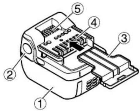
| 1 | Rechargeable battery | Aufladbare Batterie | Batterie rechargeable | Batteria ricaricabile |
| 2 | Latch Verriegelung Loquet Fermo | |||
| 3 | Battery cover Batterieabdeckung Couvercle de batterie Coperchio per la batteria | |||
| 4 | Terminals Anschlüsse | Bornes | Terminali | |
| 5 | Ventilation holes | Belüftungslöcher | Orifices de ventilation | Fori di ventilazione |
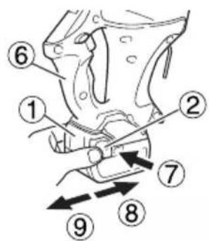
| 6 | Handle | Handgriff | Poignée | Impugnatura |
| 7 | Push | Drücken | Pousser | Spingere |
| 8 | Insert Einsatz | Insérer Inserire | ||
| 9 | Pull out | Herausziehen | Tirer | Estrarre |
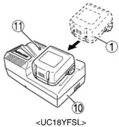
| 10 | Charger Ladegerät | Chargeur | Caricatore | |
| 11 | Pilot lamp | Kontrollampe | Lampe témoin | Spie |
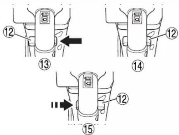
| 12 | Forward/reverse switching button | Vorwärts/Rückwärts-Schalter | Touche de direction avant/arrière | Interruttore di direzione in avanti/indietro |
| 13 | Cutting | Schneiden | Coupe-tige | Taglio |
| 14 | Lock | Schließen | Verrou | Blocco |
| 15 | Reverse | Umkehren | Marche arrière | Inverso |
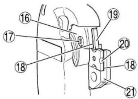
| 16 | Bracket (A) (movable side) | Klammer (A) (bewegliche Seite) | Support (A) (côté mobile) | Supporto (A) (lato mobile) |
| 17 | Hex. socket hd. bolt | Sechskantkopf-schraube | Boulon à tête hexagonale | Bullone testa esagonale |
| 18 | Spacer (used only with M6, M8 or M10) | Distanzstück (nur mit M6, M8 oder M10 verwendet) | Entretoise (à utiliser uniquement avec un cutter M6, M8 ou M10) | Spaziatore (usato solo con l’M6, l’M8 o l’M10) |
| 19 | Side without notch | Seite ohne Kerbe | Côré sans encoche | Lato senza tacca |
| 20 | Notch side | Nutenseite | Côté avec l’encoche | Lato con tacche |
| 21 | Bracket (B) (fixed side) | Klammer (B) (feste seite) | Support (B) (côté fixe) | Supporto (B) (lato fisso) |
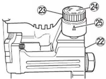
| 22 | Stud guide | Stangenführung | Guide de vis filetée | Guida vite prigioniera |
| 23 | Dial | Drehregler | Molette | Quadrante |
| 24 | Screw size display | Stangengröße-Anzeige | Dimension de la vis | Indicazione delle dimensioni della vite |
| 25 | Mark | Markierung | Marque | Segno |
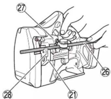
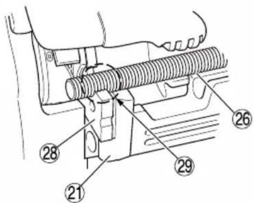
| 26 | Stud | Stange | Vis filetée | Vite prigioniera |
| 27 | Guard section | Schutzteil | Section de protection | Sezione di guardia |
| 28 | Cutter | Schneider | Cutter | Fresa |
| 29 | Correctly mesh | Richtiger Eingriff | Correctement aligné | Allineate correttamente |
| 30 | Fixed length guide (First cut the stud to the required length) | Feste Längenführung (zuerst ie stange auf richtige Länge zuschneiden) | Guide de longueur fi xe (Couper auparavant la vis fi letée selon la longueur souhaitée) | Modello lughezza fi ssa (Tagliare prima la vite prigioniera all a lughezza desiderata) |
| 31 | Stud attachment hole | Stangenansetzloch | Orifice de fixation de la vis filetée | Foro di attacco vite prigioniera |
| 32 | Necessary length | Erforderliche Länge | Longueur nécessaire | Lunghezza desiderata |
| 33 | Stud suspended from the ceiling | An der Decke befestigte Stange | Vis filetée suspendue au plafond | Vite prigioniera sospesa |
| 34 | Trigger switch | Auslöserschalter | Interrupteur à détente | Interruttore |
| 35 | Hook | Haken | Crochet | Gancio |
| 36 | Latch Verriegelung Taquet | Fermo | ||
| 37 | Grip | Griff | Poignée | Impugnatura |
| 38 | Entrance | Einführung | Entrée | Entrata |
| 39 | Pliers Zange | Pince Pinze | ||
| 40 | Remaining battery indicator switch | Ladezustand-Anzeigeschalter | Commutateur de puissance batterie résiduelle | Interruttore indicatore batteria restante |
| 41 | Remaining battery indicator lamp | Ladezustand-Kontrollleuchte | Témoin lumineux de puissance batterie résiduelle | Spia luminosa batteria restante |
| 42 | Hex. bar wrench | Sechskantschlüssel | Clef à six pans | Anello di fissaggio |
| Nederlands Español | Português | ||
| 1 | Oplaadbare batterij Batería | recargable Bateria de recarregável | |
| 2 | Vergrendeling Enganche Lingüeta | ||
| 3 | Batterijdeksel Tapa de batería | Tampa da bateria | |
| 4 | Aansluitpunten Terminales Terminais | ||
| 5 | Ventilatieopeningen | Orificios de ventilación | Orifícios de ventilação |
| 6 | Handgreep Asidero Cabo | ||
| 7 | Drukken Presionar Apertar | ||
| 8 | Insteken | Insertar | Inserir |
| 9 | Uittrekken Sacar | Retirar | |
| 10 | Acculader Cargador | Carregador | |
| 11 | Controlelampje | Lámpara piloto Lâmpada piloto | |
| 12 | Voorwaarts/achterwaarts-keuzeschakelaar | Botón conmutador de avance/retroceso | Botão de comutação avanço/retroceso |
| 13 | Knippen Corte | Corte | |
| 14 | Vergrendelen Bloqueo | Bloqueio | |
| 15 | Achterwaarts | Marcha atrás | Retrocesso |
| 16 | Beugel (A) (bewegende kant) | Soporte (A) (lado móvil) | Suporte (A) (lado móvil) |
| 17 | Inbusbout | perno de cabeza hueca hexagonal | Parafuso de cabeça cilíndrica sextavado |
| 18 | Vulplaatje (alleen bij knippen van M6, M8 of M10) | Separador (utilizado solamente con M6, M8 o M10) | Espaçador (utilizado apenas com M6, M8 ou M10) |
| 19 | Kant zonder inkeping | Lado sin la muesca | Lado sem entalhe |
| 20 | Kant met inkeping | Lado de la muesca | Lado com entalhe |
| 21 | Beugel (B) (vaste kant) | Soporte (B) (lado fijo) | Suporte (B) (lado fixo) |
| 22 | Draadeind | Guía de varilla roscada | Perno-guia |
| 23 | Schaalverdeling | Dial | Selector |
| 24 | Aanduiding van de draadiameter | Indicación del tamaño del tornillo | Visualização do tamanho do parafuso |
| 25 | Merkteken | Marca | Marca |
| 26 | Draadeind | Varilla roscada Perno | |
| 27 | Beschermkap | Sección de protección | Secção de protecção |
| 28 | Knip-element | Cortador | Cortador |
| 29 | Goed in elkaar vallend | Correctamente adaptadas | Alinhar correctamente |
| 30 | Standaardlengte-draadeind (het eerder op lengte gebrachte draadeind) | Hasta la longitud deseada (Corte en primer lugar una varilla roscada) | Guia de comprimento fi xo (Cortar primeiro o perno adequadamente) |
| 31 | Draadeind-bevestigingsopening | Orificio de fijación de la varilla roscada | Orifício de montagem do perno |
| 32 | Benodigde lengte | Longitud necesaria | Comprimento necessário |
| 33 | Uit plafond stekend draadeind | Varilla roscada suspendida del techo | Perno suspenso no tecto |
| 34 | Hoofdschakelaar | Interruptor | Interruptor do gatilho |
| 35 | Haak | Gancho | Gancho |
| 36 | Vergrendeling Cierre | Lingueta | |
| 37 | Handgreep Empuñadura | Pegas | |
| 38 | Ingang | Entrada | Entrada |
| 39 | Tang | Alicates | Alicate |
| 40 | Indicatieschakelaar resterende acculading | Interruptor de indicador de batería restante | Interruptor de indicação da autonomia da pilha |
| 41 | Indicatielampje resterende acculading | Indicador luminoso de batería restante | Luz de indicação da autonomia da pilha |
| 42 | Inbussleutel | Llave macho hexagonal | Chave sextavada |
| Symbols⚠ WARNINGThe following show symbols used for the machine. Be sure that you understand their meaning before use. | Symbole⚠ WARNINGDie folgenden Symbole werden für diese Maschine verwendet. Achten Sie darauf, diese vor der Verwendung zu verstehen. | Symboles⚠ AVERTISSEMENTLes symboles suivants sont utilisés pour l’outil. Bien se familiariser avec leur signifi cation avant d’utiliser l’outil.. | Simboli⚠ AVVERTENZADi seguito mostriamo i simboli usati per la macchina. Assicurarsi di comprenderne il signifi cato prima dell’uso. | |
 | To reduce the risk of injury, user must read instruction manual.Failure to follow the warnings and instructions may result in electric shock, fi re and/or serious injury. | Der Anwender muss die Bedienungsanleitung lesen, um das Risiko einer Verletzung zu verringern.Wenn die Warnungen und Anweisungen nicht befolgt werden, kann es zu Stromschlag, Brand und/oder ernsthaften Verletzungen kommen. | Pour réduire les risques de blessures, l’utilisateur doit lire le manuel d’utilisation.Tout manquement à observer ces avertissements et instructions peut engendrer des chocs électriques, des incendies et/ou des blessures graves. | Per ridurre il rischio di lesioni, l’utente deve leggere il manuale delle istruzioni.La mancata osservanza degli avvertimenti e delle istruzioni potrebbe essere causa di scosse elettriche, incendi e/o gravi lesioni. |
 | Only for EU countriesDo not dispose of electric tools together with household waste material!In observance of European Directive 2012/19/EU on waste electrical and electronic equipment and its implementation in accordance with national law, electric tools that have reached the end of their life must be collected separately and returned to an environmentally compatible recycling facility. | Nur für EU-LänderWerfen Sie Elektrowerkzeuge nicht in den Hausmüll!Gemäss Europäischer Richtlinie 2012/19/EU über Elektro- und Elektronik-Alteräte und Umsetzung in nationales Recht müssen verbrauchte Elektrowerkzeuge getrennt gesammelt und einer umweltgerechten Wiederververtung zugeführt werden. | Pour les pays européens uniquementNe pas jeter les appareils électriques dans les ordures ménagères!Conformément à la directive européenne 2012/19/UE relative aux déchets d’équipements électriques ou électroniques (DEEE), et à sa transposition dans la législation nationale, les appareils électriques doivent être collectés à part et être soumis à un recyclage respectueux de l’environnement. | Solo per Paesi UENon gettare le apparecchiature elettriche tra i rifi uti domestici.Secondo la Direttiva Europea 2012/19/UE sui rifi uti di apparecchiature elettriche ed elettroniche e la sua attuazione in conformità alle norme nazionali, le apparecchiature elettriche esauste devono essere raccolte separatamente, al fi ne di essere reimplegate in modo eco-compatibile. |
| Symbolen⚠ WAARSCHUWINGHieronder staan symbolen afgebeeld die van toepassing zijn op deze machine. Ú moet de betekenis hiervan begrijpen voor gebruik. | Símbolos⚠ ADVERTENCIAA continuación se muestran los símbolos usados para la máquina. Asegúrese de comprender su signifi cado antes del uso. | Símbolos⚠ AVISOA seguir aparecem os símbolos utilizados pela máquina. Assimile bem seus signifi cados antes do uso. | ||
 | Om het risico op verwondingen te verminderen, moet de gebruiker de instructiehandleiding lezen.Nalating om de waarschuwingen en instructies op te volgen kan in een elektrische schok, brand en/of ernstig letsel resulteren. | Para reducir el riesgo de lesiones, el usuario deberá leer el manual de instrucciones.Si no se siguen las advertencias e instrucciones, podría producirse una descarga eléctrica, un incendio y/o daños graves. | Para reduzir o risco de lesão, o utilizador deve ler o manual de instruções.Se não seguir todas as instruções e os avisos, pode provocar um choque eléctrico, incêndio e/ou ferimentos graves. | |
 | Alleen voor EU-landenGeef elektrisch gereedschap niet met het huisvuil mee!Volgens de Europese richtlijn 2012/19/EU inzake oude elektrische en elektronische apparaten en de toepassing daarvan binnen de nationale wetgeving, dient gebruikt elektrisch gereedschap gescheiden te worden ingezameld en te worden afgevoerd naar een recycle bedrijf dat voldoet aan de geldende milieu-eisen. | Sólo para países de la Unión Europea¡No deseche los aparatos eléctricos junto con los residuos domésticos!De conformidad con la Directiva Europea 2012/19/UE sobre residuos de aparatos eléctricos y electrónicos y su aplicación de acuerdo con la legislación nacional, las herramientas eléctricas cuya vida útil haya llegado a su fi n se deberán recoger por separado y trasladar a una planta de reciclaje que cumpla con las exigencias ecológicas. | Apenas para países da UENão deite ferramentas eléctricas no lixo doméstico!De acordo com a directiva europeia 2012/19/UE sobre ferramentas eléctricas e electrónicas usadas e a transposição para as leis nacionais, as ferramentas eléctricas usadas devem ser recolhidas em separado e encaminhadas a uma instalação de reciclagem dos materiais ecológica. |
GENERAL POWER TOOL SAFETY WARNINGS
WARNING
Read all safety warnings, instructions, illustrations and specifications provided with this power tool.
Failure to follow all instructions listed below may result in electric shock, fire and/or serious injury.
Save all warnings and instructions for future reference.
The term “power tool” in the warnings refers to your mains-operated (corded) power tool or battery-operated (cordless) power tool.
1) Work area safety
a) Keep work area clean and well lit. Cluttered or dark areas invite accidents.
b) Do not operate power tools in explosive atmospheres, such as in the presence of fl ammable liquids, gases or dust.
Power tools create sparks which may ignite the dust or fumes.
c) Keep children and bystanders away while operating a power tool.
Distractions can cause you to lose control.
2) Electrical safety
a) Power tool plugs must match the outlet.
Never modify the plug in any way.
Do not use any adapter plugs with earthed (grounded) power tools.
Unmodifi ed plugs and matching outlets will reduce risk of electric shock.
b) Avoid body contact with earthed or grounded surfaces, such as pipes, radiators, ranges and refrigerators.
There is an increased risk of electric shock if your body is earthed or grounded.
c) Do not expose power tools to rain or wet conditions.
Water entering a power tool will increase the risk of electric shock.
d) Do not abuse the cord. Never use the cord for carrying, pulling or unplugging the power tool.
Keep cord away from heat, oil, sharp edges or moving parts.
Damaged or entangled cords increase the risk of electric shock.
e) When operating a power tool outdoors, use an extension cord suitable for outdoor use.
Use of a cord suitable for outdoor use reduces the risk of electric shock.
f) If operating a power tool in a damp location is unavoidable, use a residual current device (RCD) protected supply.
Use of an RCD reduces the risk of electric shock.
3) Personal safety
a) Stay alert, watch what you are doing and use common sense when operating a power tool. Do not use a power tool while you are tired or under the influence of drugs, alcohol or medication.
A moment of inattention while operating power tools may result in serious personal injury.
b) Use personal protective equipment. Always wear eye protection.
Protective equipment such as a dust mask, non-skid safety shoes, hard hat or hearing protection used for appropriate conditions will reduce personal injuries.
c) Prevent unintentional starting. Ensure the switch is in the off-position before connecting to power source and/or battery pack, picking up or carrying the tool.
Carrying power tools with your finger on the switch or energising power tools that have the switch on invites accidents.
d) Remove any adjusting key or wrench before turning the power tool on.
A wrench or a key left attached to a rotating part of the power tool may result in personal injury.
e) Do not overreach. Keep proper footing and balance at all times.
This enables better control of the power tool in unexpected situations.
f) Dress properly. Do not wear loose clothing or jewellery. Keep your hair and clothing away from moving parts.
Loose clothes, jewellery or long hair can be caught in moving parts.
g) If devices are provided for the connection of dust extraction and collection facilities, ensure these are connected and properly used.
Use of dust collection can reduce dust-related hazards.
h) Do not let familiarity gained from frequent use of tools allow you to become complacent and ignore tool safety principles.
A careless action can cause severe injury within a fraction of a second.
4) Power tool use and care
a) Do not force the power tool. Use the correct power tool for your application.
The correct power tool will do the job better and safer at the rate for which it was designed.
b) Do not use the power tool if the switch does not turn it on and off.
Any power tool that cannot be controlled with the switch is dangerous and must be repaired.
c) Disconnect the plug from the power source and/or remove the battery pack, if detachable, from the power tool before making any adjustments, changing accessories, or storing power tools.
Such preventive safety measures reduce the risk of starting the power tool accidentally.
d) Store idle power tools out of the reach of children and do not allow persons unfamiliar with the power tool or these instructions to operate the power tool.
Power tools are dangerous in the hands of untrained users.
e) Maintain power tools and accessories. Check for misalignment or binding of moving parts, breakage of parts and any other condition that may affect the power tool's operation.
If damaged, have the power tool repaired before use.
Many accidents are caused by poorly maintained power tools.
f) Keep cutting tools sharp and clean.
Properly maintained cutting tools with sharp cutting edges are less likely to bind and are easier to control.
g) Use the power tool, accessories and tool bits etc. in accordance with these instructions, taking into account the working conditions and the work to be performed.
Use of the power tool for operations different from those intended could result in a hazardous situation.
h) Keep handles and grasping surfaces dry, clean and free from oil and grease.
Slippery handles and grasping surfaces do not allow for safe handling and control of the tool in unexpected situations.
5) Battery tool use and care
a) Recharge only with the charger specified by the manufacturer.
A charger that is suitable for one type of battery pack may create a risk of fire when used with another battery pack.
b) Use power tools only with specifically designated battery packs.
Use of any other battery packs may create a risk of injury and fire.
c) When battery pack is not in use, keep it from other metal objects, like paper clips, coins, keys, nails, screws or other small metal objects, that can make a connection from one terminal to another.
Shorting the battery terminals together may cause burns or a fire.
d) Under abusive conditions, liquid may be ejected from the battery; avoid contact. If contact accidentally occurs, flush with water. If liquid contacts eyes, additionally seek medical help.
Liquid ejected from the battery may cause irritation or burns.
e) Do not use a battery pack or tool that is damaged or modified.
Damaged or modified batteries may exhibit unpredictable behaviour resulting in fire, explosion or risk of injury.
f) Do not expose a battery pack or tool to fire or excessive temperature.
Exposure to fire or temperature above 130^ C may cause explosion.
g) Follow all charging instructions and do not charge the battery pack or tool outside the temperature range specified in the instructions.
Charging improperly or at temperatures outside the specified range may damage the battery and increase the risk of fi re.
6) Service
a) Have your power tool serviced by a qualified repair person using only identical replacement parts.
This will ensure that the safety of the power tool is maintained.
b) Never service damaged battery packs.
Service of battery packs should only be performed by the manufacturer or authorized service providers.
PRECAUTION
Keep children and infi rm persons away.
When not in use, tools should be stored out of reach of children and infi rm persons.
PRECAUTIONS FOR CORDLESS STUD CUTTER
-
Never bring the cutter near your fingers when operating the switch.
-
Do not use for cutting screws other than soft steel studs. This tool is designed especially for cutting of soft steel studs. Using this tool for brass or stainless steel screws could cause distortions in the screw threads, thereby preventing insertion of nuts.
Never use to cut tempered bolts, screws of differing sizes, reinforcing rods, etc.
-
Use by changing the special cutters according to the size of the studs. Cutting with cutters of the wrong size could damage to the continuous thread studs or the cutter edges.
-
Make sure that the threads on the studs and those on the cutter are correctly meshed before starting to cut. Cutting when the threads are not meshed could cause damage to the studs and the cutter.
-
If the cutter has been attached in the wrong direction or the bolt for cutter attachment is loose, this could cause damage to the cutter edge and could lead to premature damage to the main unit.
Be very careful to attach the cutter correctly.
-
Cutting studs at short lengths of 10 millimeters or less will create an insufficient meshing length between the cutter and studs, thus causing damage to the cutter. Always cut at lengths of more than 10 millimeters.
-
When cutting studs secured to narrow locations, be sure that there is at least 8 millimeters between the stud and the surrounding materials.
If the distance is less than 8 millimeters the cutter could contact the surrounding materials, thereby causing damage to the cutter and the main unit.
-
When inspecting, cleaning or replacing the cutter, be sure to remove the battery from the main unit. The switch could be turned on accidentally, thereby causing accidents.
-
When using this equipment at heights, make doubly sure prior to use that there is no one standing in the area immediately below you. Place the tool in a safe and stable place when not using at the moment.
-
Always charge the battery at a temperature of 0 - 40^ . A temperature of less than 0^ will result in over charging which is dangerous. The battery cannot be charged at a temperature greater than 40^ . The most suitable temperature for charging is that of 20 - 25^ .
-
Do not use the charger continuously.
When one charging is completed, leave the charger for about 15 minutes before the next charging of battery.
-
Do not allow foreign matter to enter the hole for connecting the rechargeable battery.
-
Never disassemble the rechargeable battery and s charger.
-
Never short-circuit the rechargeable battery. Short-circuiting the battery will cause a great electric current and overheat. It results in burn or damage to the battery.
-
Do not dispose of the battery in fire.
If the battery is burnt, it may explode.
- Do not insert object into the air ventilation slots of the charger.
Inserting metal objects or inflammables into the charger air ventilation slots will result in electrical shock hazard or damaged charger. - Bring the battery to the shop from which it was purchased as soon as the post-charging battery life becomes too short for practical use. Do not dispose of the exhausted battery.
- Using an exhausted battery will damage the charger.
CAUTION ON LITHIUM-ION BATTERY
To extend the lifetime, the lithium-ion battery equips with the protection function to stop the output.
In the cases of 1 to 3 described below, when using this product, even if you are pulling the switch, the motor may stop. This is not the trouble but the result of protection function.
- When the battery power remaining runs out, the motor stops.
In such case, charge it up immediately.
-
If the tool is overloaded, the motor may stop. In this case, release the switch of tool and eliminate causes of overloading. After that, you can use it again.
-
If the battery is overheated under overload work, the battery power may stop.
In this case, stop using the battery and let the battery cool. After that, you can use it again.
Furthermore, please heed the following warning and caution.
WARNING
In order to prevent any battery leakage, heat generation, smoke emission, explosion and ignition beforehand, please be sure to heed the following precautions.
- Make sure that swarf and dust do not collect on the battery.
During work make sure that swarf and dust do not fall on the battery.
○ Make sure that any swarf and dust falling on the power tool during work do not collect on the battery.
- Do not store an unused battery in a location exposed to swarf and dust.
Before storing a battery, remove any swarf and dust that may adhere to it and do not store it together with metal parts (screws, nails, etc.).
-
Do not pierce battery with a sharp object such as a nail, strike with a hammer, step on, throw or subject the battery to severe physical shock.
-
Do not use an apparently damaged or deformed battery.
SPECIFICATIONS
- Do not use the battery in reverse polarity.
- Do not connect directly to an electrical outlets or car cigarette lighter sockets.
- Do not use the battery for a purpose other than those specified.
- If the battery charging fails to complete even when a specified recharging time has elapsed, immediately stop further recharging.
- Do not put or subject the battery to high temperatures or high pressure such as into a microwave oven, dryer, or high pressure container.
- Keep away from fire immediately when leakage or foul odor are detected.
- Do not use in a location where strong static electricity generates.
- If there is battery leakage, foul odor, heat generated, discolored or deformed, or in any way appears abnormal during use, recharging or storage, immediately remove it from the equipment or battery charger, and stop use.
- Do not immerse the battery or allow any fluids to flow inside. Conductive liquid ingress, such as water cause damage resulting in fire or explosion. Store your battery in a cool, dry place, away from combustible and flammable items. Corrosive gas atmospheres must be avoided.
- If liquid leaking from the battery gets into your eyes, do not rub your eyes and wash them well with fresh clean water such as tap water and contact a doctor immediately.
If left untreated, the liquid may cause eye-problems. - If liquid leaks onto your skin or clothes, wash well with clean water such as tap water immediately.
There is a possibility that this can cause skin irritation. - If you find rust, foul odor, overheating, discolor, deformation, and/or other irregularities when using the battery for the first time, do not use and return it to your supplier or vendor.
If an electrically conductive foreign terminals of the lithium ion battery, a short-circuit may occur resulting in the risk of fire. Please observe the following matters when storing the battery.
○ Do not place electrically conductive cuttings, nails, steel wire, copper wire or other wire in the storage case.
○ Either install the battery in the power tool or store by securely pressing into the battery cover until the ventilation holes are concealed to prevent short-circuits (See Fig. 1).
CAUTION
WARNING
POWER TOOL
| Model | CL14DSL | CL18DSL | ||||
| No-load stroke | 30 min ^-1 | |||||
| Capacity: Soft steel studs(Size of studs for cutting) | ○ M10 × 1.5 ○ M8 × 1.25 ○ M6 × 1○ W3/8" × 1.5875 | |||||
| Rechargeable battery | BSL1430:Li-ion 14.4 V(3.0 Ah 8 cells) | BSL1440:Li-ion 14.4 V(4.0 Ah 8 cells) | BSL1450:Li-ion 14.4 V(5.0 Ah 8 cells) | BSL1830:Li-ion 18 V(3.0 Ah 10 cells) | BSL1840:Li-ion 18 V(4.0 Ah 10 cells) | BSL1850:Li-ion 18 V(5.0 Ah 10 cells) |
| Weight* | 2.8 – 3.1 kg | 2.9 – 3.5 kg | ||||
* Weight according to EPTA-Procedure 01/2014. Depending on attached battery. The heaviest weight is measured with BSL1460 (CL14DSL) and BSL36B18 (CL18DSL).
CHARGER
| Model UC18YFSL | |
| Charging voltage 14 | 4 V – 18 V |
| Weight 0.5 kg |
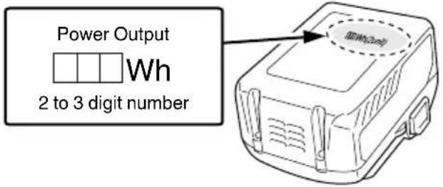
REGARDING LITHIUM-ION BATTERY TRANSPORTATION
When transporting a lithium-ion battery, please observe the following precautions.
WARNING
Notify the transporting company that a package contains a lithium-ion battery, inform the company of its power output and follow the instructions of the transportation company when arranging transport.
○ Lithium-ion batteries that exceed a power output of 100 Wh are considered to be in the freight classification of Dangerous Goods and will require special application procedures.
For transportation abroad, you must comply with international law and the rules and regulations of the destination country.
STANDARD ACCESSORIES
| CL14DSL | 1 Charger ...... 12 Battery ...... 23 Battery cover ......4 Plastic case ......5 Hexagon bar wrench ...... 16 M8 Cutter ......7 M8 Spacer ......8 M8 Trimmer ...... |
| CL14DSL (NN) | Without charger, battery, battery cover and plastic case |
| CL18DSL | 1 Charger ...... 12 Battery ...... 23 Battery cover ......4 Plastic case ......5 Hexagon bar wrench ...... 16 M8 Cutter or M10 Cutter ...... 27 M8 Spacer or M10 Spacer ...... 28 M8 Trimmer or M10 Trimmer ...... 1 |
| CL18DSL (NN) | Without charger, battery, battery cover and plastic case |
Standard accessories are subject to change without notice.
OPTIONAL ACCESSORIES (sold separately)
1. Battery
(BSL1430, BSL1440, BSL1450, BSL1460)
(BSL1830, BSL1840, BSL1850, BSL1860)
(BSL36..18)
- Cutter
| Screw size | Combining cutters and spacers | |
| M10 × 1.5 | M10 Cutter .....2M10 Spacer .....2 | 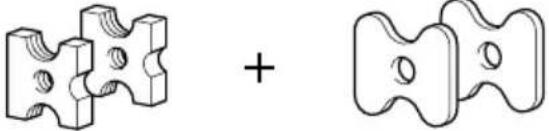 |
| M8 × 1.25 | M8 Cutter .....2M8 Spacer .....2 | |
| M6 × 1 | M6 Cutter .....2M6 Spacer .....2 | |
| W3/8" × 1.5875 | W3/8" Cutter .....2 | 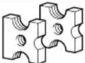 |
- Trimmer
| Screw size | 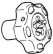 |
| M10 × 1.5 | |
| M8 × 1.25 | |
| M6 × 1 | |
| W3/8" × 1.5875 |
Optional accessories are subject to change without notice.
APPLICATIONS
○ Cutting of soft steel studs.
BATTERY REMOVAL/INSTALLATION
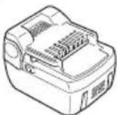
1. Battery removal
Hold the handle tightly and push the battery latch to remove the battery (see Figs. 1 and 2).
CAUTION
Never short-circuit the battery.
2. Battery installation
Insert the battery while observing its polarities (see Fig. 2).
CHARGING
Before using the power tool, charge the battery as follows.
1. Connect the charger's power cord to a receptacle.
When the power cord is connected, the charger's pilot lamp will blink in red. (At 1-second intervals)
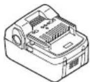
2. Insert the battery into the charger.
Firmly insert the battery into the charger, as shown in Fig. 3.
3. Charging
When inserting a battery in the charger, charging will commence and the pilot lamp will light continuously in red. When the battery becomes fully recharged, the pilot lamp will blink in red. (At 1-second intervals) (See Table 1)
(1) Pilot lamp indication
The indications of the pilot lamp will be as shown in Table 1, according to the condition of the charger or the rechargeable battery.
Table 1
| Indications of the pilot lamp | ||||
| The pilot lamp lights or blinks. | Before charging | Blinks(red) | Lights for 0.5 seconds. Does not light for 0.5 seconds. (off for 0.5 seconds) | |
| While charging | Lights(red) | Lights continuously | ||
| Charging complete | Blinks(red) | Lights for 0.5 seconds. Does not light for 0.5 seconds. (off for 0.5 seconds) | ||
| Charging impossible | Flickers(red) | Lights for 0.1 seconds. Does not light for 0.1 seconds. (off for 0.1 seconds)■ ■ ■ ■ ■ ■ ■ ■ ■ ■ ■ ■ ■ ■ ■ ■ ■ ■ ■ ■ ■ ■ ■ ■ ■ ■ ■ ■ ■ ■ ■ ■ ■ ■ ■ ■ ■ ■ ■ ■ ■ ■ ■ ■ ■ ■ ■ ■ ■ ■ ■ ■ ■ ■ ■ ■ ■ ■ ■ ■ ■ ■ ■ ■ ■ ■ ■ ■ ■ ■ ■ ■ ■ ■ ■ ■ ■ ■ ■ ■ ■ ■ ■ ■ ■ ■ ■ ■ ■ ■ ■ ■ ■ ■ ■ ■ ■ ■ ■ ■ ■ □□□□□□□□□□□□□□□□□□□□□□□□□□□□□□□□□□□□□□□□□□□□□□□□□□□□□□□□□□□□□□□□□□□□□□□□□□□□□□□□□□□□□□□□□□□□□□□□□□□□□○□□□□□□□□□□□□□□□□□□□□□□□□□□□□□□□□□□□□□□□□□□□□□□□□□□□□□□□□□□□□□□□□□□□□□□□□□□□□□□□□□□□□□□□□□□□□□□□□□□□ □□□□□□□□□□□□□□□□□□□□□□□□□□□□□□□□□□□□□□□□□□□□□□□□□□□□□□□□□□□□□□□□□□□□□□□□□□□□□□□□□□□□□□□□□□□□□□□□□□ □ □ □ □ □ □ □ □ □ □ □ □ □ □ □ □ □ □ □ □ □ □ □ □ □ □ □ □ □ □ □ □ □ □ □ □ □ □ □ □ □ □ □ □ □ □ □ □ □ □ ▢ ▢ ▢ ▢ ▢ ▢ ▢ ▢ ▢ ▢ ▢ ▢ ▢ ▢ ▢ ▢ ▢ ▢ ▢ ▢ ▢ ▢ ▢ ▢ ▢ ▢ ▢ ▢ ▢ ▢ ▢ ▢ ▢ ▢ ▢ ▢ ▢ ▢ ▢ ▢ ▢ ▢ ▢ ▢ ▢ ▢ ▢ ▢ ▢ ▢ ▩ ▩ ▩ ▩ ▩ ▩ ▩ ▩ ▩ ▩ ▩ ▩ ▩ ▩ ▩ ▩ ▩ ▩ ▩ ▩ ▩ ▩ ▩ ▩ ▩ ▩ ▩ ▩ ▩ ▩ ▩ ▩ ▩ ▩ ▩ ▩ ▩ ▩ ▩ ▩ ▩ ▩ ▩ ▩ ▩ ▩ ▩ ▩ ▩ ▩ ▢ ▢ ▢ ▢ ▢ ▢ ▢ ▢ ▢ ▢ ▢ ▢ ▢ ▢ ▢ ▢ ▢ ▢ ▢ ▢ ▢ ▢ ▢ ▢ ▢ ▢ ▢ ▢ ▢ ▢ ▢ ▢ ▢ ▢ ▢ ▢ ▢ ▢ ▢ ▢ ▢ ▢ ▢ ▢ ▢ ▢ ▢ ▢ ▢ □ □ □ □ □ □ □ □ □ □ □ □ □ □ □ □ □ □ □ □ □ □ □ □ □ □ □ □ □ □ □ □ □ □ □ □ □ □ □ □ □ □ □ □ □ □ □ □ □ △ △ △ △ △ △ △ △ △ △ △ △ △ △ △ △ △ △ △ △ △ △ △ △ △ △ △ △ △ △ △ △ △ △ △ △ △ △ △ △ △ △ △ △ △ △ △ △ △ △ ▸ ▸ ▸ ▸ ▸ ▸ ▸ ▸ ▸ ▸ ▸ ▸ ▸ ▸ ▸ ▸ ▸ ▸ ▸ ▸ ▸ ▸ ▸ ▸ ▸ ▸ ▸ ▸ ▸ ▸ ▸ ▸ ▸ ▸ ▸ ▸ ▸ ▸ ▸ ▸ ▸ ▸ ▸ ▸ ▸ ▸ ▸ ▸ ▸ ▸ ▪ ▪ ▪ ▪ ▪ ▪ ▪ ▪ ▪ ▪ ▪ ▪ ▪ ▪ ▪ ▪ ▪ ▪ ▪ ▪ ▪ ▪ ▪ ▪ ▪ ▪ ▪ ▪ ▪ ▪ ▪ ▪ ▪ ▪ ▪ ▪ ▪ ▪ ▪ ▪ ▪ ▪ ▪ ▪ ▪ ▪ ▪ ▪ ▪ ▪ ▫ ▫ ▫ ▫ ▫ ▫ ▫ ▫ ▫ ▫ ▫ ▫ ▫ ▫ ▫ ▫ ▫ ▫ ▫ ▫ ▫ ▫ ▫ ▫ ▫ ▫ ▫ ▫ ▫ ▫ ▫ ▫ ▫ ▫ ▫ ▫ ▫ ▫ ▫ ▫ ▫ ▫ ▫ ▫ ▫ ▫ ▫ ▫ ▫ ▫ ▪ ▪ ▪ ▪ ▪ ▪ ▪ ▪ ▪ ▪ ▪ ▪ ▪ ▪ ▪ ▪ ▪ ▪ ▪ ▪ ▪ ▪ ▪ ▪ ▪ ▪ ▪ ▪ ▪ ▪ ▪ ▪ ▪ ▪ ▪ ▪ ▪ ▪ ▪ ▪ ▪ ▪ ▪ ▪ ▪ ▪ ▪ ▪ ▪ ▸ ▸ ▸ ▸ ▸ ▸ ▸ ▸ ▸ ▸ ▸ ▸ ▸ ▸ ▸ ▸ ▸ ▸ ▸ ▸ ▸ ▸ ▸ ▸ ▸ ▸ ▸ ▸ ▸ ▸ ▸ ▸ ▸ ▸ ▸ ▸ ▸ ▸ ▸ ▸ ▸ ▸ ▸ ▸ ▸ ▸ ▸ ▸ ▸ ▩ ▩ ▩ ▩ ▩ ▩ ▩ ▩ ▩ ▩ ▩ ▩ ▩ ▩ ▩ ▩ ▩ ▩ ▩ ▩ ▩ ▩ ▩ ▩ ▩ ▩ ▩ ▩ ▩ ▩ ▩ ▩ ▩ ▩ ▩ ▩ ▩ ▩ ▩ ▩ ▩ ▩ ▩ ▩ ▩ ▩ ▩ ▩ ▩ ▸ ▸ ▸ ▸ ▸ ▸ ▸ ▸ ▸ ▸ ▸ ▸ ▸ ▸ ▸ ▸ ▸ ▸ ▸ ▸ ▸ ▸ ▸ ▸ ▸ ▸ ▸ ▸ ▸ ▸ ▸ ▸ ▸ ▸ ▸ ▸ ▸ ▸ ▸ ▸ ▸ ▸ ▸ ▸ ▸ ▸ ▸ ▸ ▸ ▼ ▸ ▸ ▸ ▸ ▸ ▸ ▸ ▸ ▸ ▸ ▸ ▸ ▸ ▸ ▸ ▸ ▸ ▸ ▸ ▸ ▸ ▸ ▸ ▸ ▸ ▸ ▸ ▸ ▸ ▸ ▸ ▸ ▸ ▸ ▸ ▸ ▸ ▸ ▸ ▸ ▸ ▸ ▸ ▸ ▸ ▸ ▸ ▸ ▸ ▅ ▅ ▅ ▅ ▅ ▅ ▅ ▅ ▅ ▅ ▅ ▅ ▅ ▅ ▅ ▅ ▅ ▅ ▅ ▅ ▅ ▅ ▅ ▅ ▅ ▅ ▅ ▅ ▅ ▅ ▅ ▅ ▅ ▅ ▅ ▅ ▅ ▅ ▅ ▅ ▅ ▅ ▅ ▅ ▅ ▅ ▅ ▅ ▅ ▅ ▵ ▵ ▵ ▵ ▵ ▵ ▵ ▵ ▵ ▵ ▵ ▵ ▵ ▵ ▵ ▵ ▵ ▵ ▵ ▵ ▵ ▵ ▵ ▵ ▵ ▵ ▵ ▵ ▵ ▵ ▵ ▵ ▵ ▵ ▵ ▵ ▵ ▵ ▵ ▵ ▵ ▵ ▵ ▵ ▵ ▵ ▵ ▵ ▵ ▵ ▶ ▶ ▶ ▶ ▶ ▶ ▶ ▶ ▶ ▶ ▶ ▶ ▶ ▶ ▶ ▶ ▶ ▶ ▶ ▶ ▶ ▶ ▶ ▶ ▶ ▶ ▶ ▶ ▶ ▶ ▶ ▶ ▶ ▶ ▶ ▶ ▶ ▶ ▶ ▶ ▶ ▶ ▶ ▶ ▶ ▶ ▶ ▶ ▶ ▶ ▆ ▆ ▆ ▆ ▆ ▆ ▆ ▆ ▆ ▆ ▆ ▆ ▆ ▆ ▆ ▆ ▆ ▆ ▆ ▆ ▆ ▆ ▆ ▆ ▆ ▆ ▆ ▆ ▆ ▆ ▆ ▆ ▆ ▆ ▆ ▆ ▆ ▆ ▆ ▆ ▆ ▆ ▆ ▆ ▆ ▆ ▆ ▆ ▆ ▆ ▮ ▮ ▮ ▮ ▮ ▮ ▮ ▮ ▮ ▮ ▮ ▮ ▮ ▮ ▮ ▮ ▮ ▮ ▮ ▮ ▮ ▮ ▮ ▮ ▮ ▮ ▮ ▮ ▮ ▮ ▮ ▮ ▮ ▮ ▮ ▮ ▮ ▮ ▮ ▮ ▮ ▮ ▮ ▮ ▮ ▮ ▮ ▮ ▮ ▮ ▯ ▯ ▯ ▯ ▯ ▯ ▯ ▯ ▯ ▯ ▯ ▯ ▯ ▯ ▯ ▯ ▯ ▯ ▯ ▯ ▯ ▯ ▯ ▯ ▯ ▯ ▯ ▯ ▯ ▯ ▯ ▯ ▯ ▯ ▯ ▯ ▯ ▯ ▯ ▯ ▯ ▯ ▯ ▯ ▯ ▯ ▯ ▯ ▯ ▯ ▱ ▱ ▱ ▱ ▱ ▱ ▱ ▱ ▱ ▱ ▱ ▱ ▱ ▱ ▱ ▱ ▱ ▱ ▱ ▱ ▱ ▱ ▱ ▱ ▱ ▱ ▱ ▱ ▱ ▱ ▱ ▱ ▱ ▱ ▱ ▱ ▱ ▱ ▱ ▱ ▱ ▱ ▱ ▱ ▱ ▱ ▱ ▱ ▱ ▱ ▲ ▲ ▲ ▲ ▲ ▲ ▲ ▲ ▲ ▲ ▲ ▲ ▲ ▲ ▲ ▲ ▲ ▲ ▲ ▲ ▲ ▲ ▲ ▲ ▲ ▲ ▲ ▲ ▲ ▲ ▲ ▲ ▲ ▲ ▲ ▲ ▲ ▲ ▲ ▲ ▲ ▲ ▲ ▲ ▲ ▲ ▲ ▲ ▲ ▲ △ △ △ △ △ △ △ △ △ △ △ △ △ △ △ △ △ △ △ △ △ △ △ △ △ △ △ △ △ △ △ △ △ △ △ △ △ △ △ △ △ △ △ △ △ △ △ △ △ ▴ ▴ ▴ ▴ ▴ ▴ ▴ ▴ ▴ ▴ ▴ ▴ ▴ ▴ ▴ ▴ ▴ ▴ ▴ ▴ ▴ ▴ ▴ ▴ ▴ ▴ ▴ ▴ ▴ ▴ ▴ ▴ ▴ ▴ ▴ ▴ ▴ ▴ ▴ ▴ ▴ ▴ ▴ ▴ ▴ ▴ ▴ ▴ ▴ ▴ ▵ ▵ ▵ ▵ ▵ ▵ ▵ ▵ ▵ ▵ ▵ ▵ ▵ ▵ ▵ ▵ ▵ ▵ ▵ ▵ ▵ ▵ ▵ ▵ ▵ ▵ ▵ ▵ ▵ ▵ ▵ ▵ ▵ ▵ ▵ ▵ ▵ ▵ ▵ ▵ ▵ ▵ ▵ ▵ ▵ ▵ ▵ ▵ ▵ ▴ ▴ ▴ ▴ ▴ ▴ ▴ ▴ ▴ ▴ ▴ ▴ ▴ ▴ ▴ ▴ ▴ ▴ ▴ ▴ ▴ ▴ ▴ ▴ ▴ ▴ ▴ ▴ ▴ ▴ ▴ ▴ ▴ ▴ ▴ ▴ ▴ ▴ ▴ ▴ ▴ ▴ ▴ ▴ ▴ ▴ ▴ ▴ ▴ ▸ ▸ ▸ ▸ ▸ ▸ ▸ ▸ ▸ ▸ ▸ ▸ ▸ ▸ ▸ ▸ ▸ ▸ ▸ ▸ ▸ ▸ ▸ ▸ ▸ ▸ ▸ ▸ ▸ ▸ ▸ ▸ ▸ ▸ ▸ ▸ ▸ ▸ ▸ ▸ ▸ ▸ ▸ ▸ ▸ ▸ ▸ ▸ ▸ ▦ ▸ ▸ ▸ ▸ ▸ ▸ ▸ ▸ ▸ ▸ ▸ ▸ ▸ ▸ ▸ ▸ ▸ ▸ ▸ ▸ ▸ ▸ ▸ ▸ ▸ ▸ ▸ ▸ ▸ ▸ ▸ ▸ ▸ ▸ ▸ ▸ ▸ ▸ ▸ | ||
(2) Regarding the temperatures and charging time of the battery.
The temperatures and charging time will become as shown in Table 2
Table 2
| Charger | UC18YFSL | ||||
| Battery | Type of battery | Li-ion | |||
| Temperatures at which the battery can be recharged | 0°C - 50°C | ||||
| Charging voltage | V | 1 | 4 | 4 | |
| Charging time, approx. (At 20°C) | min. | BSL14xx series | BSL18xx series | Multi volt series | |
| (8 cells) | (10 cells) | (10 cells) | |||
| BSL1430:45 | BSL1830:45 | ||||
| BSL1440:60 | BSL1840:60 | BSL36A18:75 | |||
| BSL1450:75 | BSL1850:75 | BSL36B18:120 | |||
| BSL1460:90 | BSL1860:90 | ||||
NOTE
The charging time may vary according to temperature and power source voltage.
-
Disconnect the charger's power cord from the receptacle.
-
Hold the charger firmly and pull out the battery. NOTE
After operation, pull out batteries from the charger first, and then keep the batteries properly.
Regarding electric discharge in case of new batteries, etc.
As the internal chemical substance of new batteries and batteries that have not been used for an extended period is not activated, the electric discharge might be low when using them the first and second time. This is a temporary phenomenon, and normal time required for recharging will be restored by recharging the batteries 2 – 3 times.
How to make the batteries perform longer
(1) Recharge the batteries before they become completely exhausted.
When you feel that the power of the tool becomes weaker, stop using the tool and recharge its battery. If you continue to use the tool and exhaust the electric current, the battery may be damaged and its life will become shorter.
(2) Avoid recharging at high temperatures.
A rechargeable battery will be hot immediately after use. If such a battery is recharged immediately after use, its internal chemical substance will deteriorate, and the battery life will be shortened. Leave the battery and recharge it after it has cooled for a while.
CAUTION
When the battery charger has been continuously used, the battery charger will be heated, thus constituting the cause of the failures. Once the charging has been completed, give 15 minutes rest until the next charging.
☐ If the battery is recharged when it is warm due to battery use or exposure to sunlight, the pilot lamp map light in green.
The battery will not be recharged. In such a case, let the battery cool before charging.
When the pilot lamp flickers in red (at 0.2-second intervals), check for and take out any foreign objects in the charger's battery installation hole. If there are no foreign objects, it is probable that the battery or charger is malfunctioning. Take it to your authorized Service Center.
PRIOR TO OPERATION
- Preparing and checking the work environment
Make sure that the work site meets all the conditions laid forth in the precautions.
- Checking the battery
Make sure that the battery is installed firmly. If it is at all loose it could come off and cause an accident.
- Setting the forward/reverse switching button
(1) Push the forward/reverse switching button from the right as shown in Fig. 4 (a). Cutting is possible.
(2) By setting the forward/reverse switching button in the lock position as shown in Fig. 4 (b), the motor will not operate even if the trigger switch is pulled. When carrying or storing the main unit or when stopping operations, set the forward/reverse switching button to the lock position (Fig. 4 (b)).
(3) Push the forward/reverse switching button from the left as shown in Fig. 4 (c). With the button held down, pull the trigger switch so that the cutter can be removed from the stud. Only set to this position if the rechargeable battery is worn out and the unit stops operating during cutting. Immediately turn off the switch after the cutter has been removed from the stud.
CAUTION
Do not attempt to cut in the reverse position (Fig. 4 (c)). If you attempt to cut in this position, there will be an overload on the motor and cutting will not be possible. Never apply excessive force to the main unit as this can cause damage to the unit.
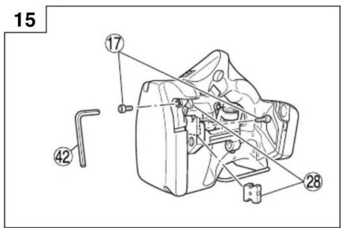
- Check the cutter size, attachment direction, attachment bolt and spacer
(1) The cutter size differs according to the size of the studs to be cut. Make sure that a cutter is attached that conforms to the size of the studs to be cut.
(2) Cutter attachment includes directionality. Make sure that the cutter has been attached so that the side without the notch on the cutter can be seen on bracket (A) (movable side) when the main unit is viewed from the front or that the notch on the cutter surface can be seen on bracket (B) (fi xed side).
(3) Use the accessory hexagonal wrench to insure that the hex. socket hd. bolt for attaching the cutter is securely tightened (Fig. 5). Using the equipment while the bolt is loose could cause damage to the main unit and cutter.
(4) Depending on the size of the studs it may be necessary to attach special spacers to the cutter.
① When using the M10, M8 or M6 cutter
Check and confirm that the accessory M6, M8 or M10 spacers are correctly inserted respectively between bracket (A) and the cutter and bracket (B) and the cutter (Fig. 5).
CAUTION
If the spacers are not attached or if spacers of the wrong size are used, the threads of the cutter and the studs will not properly mesh, thereby causing damage to the studs and the cutter edge. Be sure to attach spacers correctly.
② When using the W3/8" cutter
No spacers are required. Check and confirm that only the cutter is attached.
For details, refer to the section on "Cutter life and replacement".
5. Correctly insert the stud guide
The stud guide is used to prevent tilting during cutting of studs. Correctly adjust the dial calibration to the mark (△) depending on the size of the stud to be cut (Fig. 6). CAUTION
If the size of the stud and the dial position to do not agree, the cut section may be subjected to burrs or its shape may be distorted, which may result in damage to the main unit.
HOW TO USE
CAUTION
- Never bring the cutter near your fingers when operating the trigger switch.
When cutting short studs, take caution as to not place your fingers in the space between the short stud and main unit, such as the guard section (see Fig. 7), battery, etc.
○ After cutting, the cut section of the stud is very sharp and therefore dangerous. Be very careful when handling the stud.
1. Normal Cutting Method
(1) Pull the trigger switch and move bracket (A), stopping with the cutter in the open position shown in Fig. 7.
(2) As shown in Fig. 8, set the stud to be cut in the cutter on the bracket (B) side, making sure that the threads correctly mesh with each other.
(3) While maintaining the stud in a horizontal position, pull the trigger switch all the way to cut the stud (Fig. 7).
(4) After cutting turn off the switch with bracket (A) facing directly upward. The unit stops with the cutter in the open position, thus making it easier to proceed to the next operation.
2. Number of cuttings (per battery charging)
Refer to the chart below for the number of cuttings per battery charging.
Table 3
| Battery M10 M8 M6 W3/8” | ||||
| BSL1430 | 660 | 1020 | 1520 | 740 |
| BSL1440 | 880 | 1360 | 2020 | 980 |
| BSL1450 | 1100 | 1700 | 2520 | 1220 |
| BSL1830 | 790 | 1220 | 1820 | 920 |
| BSL1840 | 1050 | 1620 | 2420 | 1220 |
| BSL1850 | 1310 | 2020 | 3020 | 1520 |
The number of cuttings can also vary somewhat according to the ambient temperature, characteristics of the battery and the condition of the cutter.
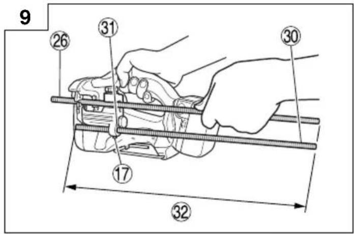
3. Cutting fixed lengths (Fig. 9)
When cutting several studs to the same length, using the equipment in the following way will making cutting operations more efficient.
(1) First cut one stud to the required length, and then use it as a fixed length guide.
(2) Insert the stud used as a fixed length guide in the stud attachment hole found on the main unit stud guide and use the hexagonal bar wrench to tighten and secure the hex. socket hd. bolt. Adjust at this time so that the distance between the end of the stud used as a fixed length and the cutter is the necessary length.
(3) Insert the stud for cutting in the cutter, aligning the end with that of the stud used as a cutting guide, and then cut the stud.
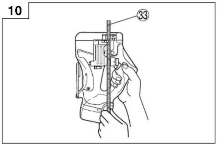
4. Cutting studs that are already secured (Fig. 10)
When cutting studs that are suspended from the ceiling or secured to walls or floors.
When inserting the stud in the cutter, the meshing of the stud thread and cutter thread is unstable. In such a case, after inserting the stud in the cutter, lightly pull the trigger switch to close the cutter at low speed and then completely mesh the stud and the upper and lower cutters. Next, pull the trigger switch all the way to cut the stud.
CAUTION
Use your one hand to hold the stud on the side released by cutting to insure that it does not fall unexpectedly.
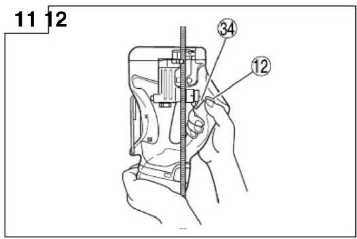
5. Removing the screw from the unit during cutting operations
If the battery wears out during cutting operations so that the motor stops rotating, pull the trigger switch while pushing the forward/reverse switching button to the reverse side (Fig. 4 (c)). The motor will rotate in the opposite direction and it will be possible to remove the stud from the cutter (Fig. 11).
CAUTION
○ When removing a stud that is suspended from the ceiling, hold the main unit with both hands to prevent any possibility of the stud falling.
- Immediately turn off the switch once the cutter is free from the stud. If you attempt to do this with the switch turned on, the cutter might cut into the stud again.
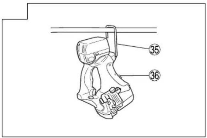
6. Using the hook
The hook can be used to hang up the unit temporarily during operations (Fig. 12).
CAUTION
The hook should never be used to hang the unit on your person.
When using the hook, check to make sure that the main unit will not slip and fall, or become unstable by the wind, etc.
Never hang the unit from your belt or trousers as this could cause accidents.
NOTE
During normal use or during storage, store the hook in the latch found on the bottom of the main unit.
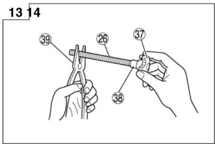
7. Using the trimmer
NOTE: Use a special trimmer that is suitable for the size of the stud.
If it is difficult for the nut to enter the cutting position, either use a wrench to firmly tighten the nut or use the accessory trimmer to remove the flange on the screw thread.
Insert the stud in the hole on the grip. Use a pliers to retain the stud and rotate the trimmer 5 or 6 times to the right to remove the flange and then rotate in the opposite direction to remove the trimmer (Fig. 13).
CAUTION
This trimmer is specially designed for Studs Cutter. The fl ange on studs cut with a hacksaw or disc grinder is too large for this trimmer so that the trimmer does not rotate and it is not possible to remove fl ange.
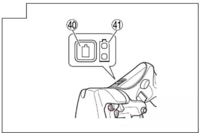
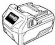
8. About Remaining Battery Indicator
When pressing the remaining battery indicator switch, the remaining battery indicator lamp lights and the battery remaining power can be checked. (Fig. 14) When releasing your finger from the remaining battery indicator switch, the remaining battery indicator lamp goes off. The Table 4 shows the state of remaining battery indicator lamp and the battery remaining power.
Table 4
| State of lamp Battery Remaining Power | |
 | The battery remaining power is enough. |
 | The battery remaining power is a half. |
| [6WC] | The battery remaining power is nearly empty.Re-charge the battery soonest possible. |
As the remaining battery indicator shows somewhat differently depending on ambient temperature and battery characteristics, read it as a reference.
NOTE
○ Do not give a strong shock to the switch panel or break it. It may lead to a trouble.
To save the battery power consumption, the remaining battery indicator lamp lights while pressing the remaining battery indicator switch.
CUTTER LIFE AND REPLACEMENT
1. Cutter life
As is shown in Fig. 16, repeated cutting can cause breaking and warping of the cutter edge. Using the cutter in this condition can produce flange on the cutting location of the studs so that the threads are distorted. This will prevent clean cuts and make it impossible to insert the nut.
Breaking
Warping
Fig. 16
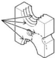
As is shown in Fig. 17, the edge is found on four locations on the cutter. Use the method described below to change the attachment direction of the cutter to allow a total of four usages.
If the nut does not fit on the screw due to breaking and warping of the edge, change the cutter attachment direction to use the edge without breaking and warping or replace with a new cutter.
Four edges on the cutter
natural_image
Technical line drawing of a mechanical component with no visible text or symbolsFig. 17
2. Changing the cutter attachment direction or replacing the cutter
(1) Before removing:
① Pull the trigger switch and move bracket (A), stopping with the cutter in the open position.
② Set the forward/reverse switching button to the lock position (Fig. 4 (b)).
③ Remove the rechargeable battery from the main unit.
(2) Removal Use the accessory hexagonal bar wrench to remove the hex. socket hd. bolt. It is now possible to remove the cutter and spacer.
(3) Before attaching
① There are four edges on the cutter. As shown in Fig. 18, by changing the position of the edge it is possible to use the blade four times.
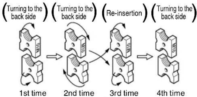
flowchart
graph LR
    A["1st time"] --> B["2nd time"]
    B --> C["3rd time"]
    C --> D["4th time"]
    style A fill:#f9f,stroke:#333
    style B fill:#f9f,stroke:#333
    style C fill:#f9f,stroke:#333
    style D fill:#f9f,stroke:#333
Fig. 18
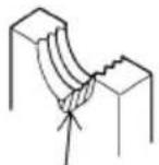
② There is directionality for cutter attachment in order to change the position of the edge. Check that the cutter has been attached so that the side without the notch on the cutter can be seen on bracket (A) (movable side) when seen from the main unit viewed from the front or that the notch on the cutter surface on bracket (B) (fixed side) can be seen (Figs. 5 and 19).
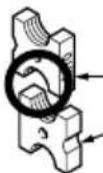
Side without notch
Notch side
Fig. 19
DO Fig. 19
③ If there is breakage or warping on the cutter edge or if there are bulges on the cutter attachment surface, use a file to the areas flat.
④ Use brush to remove the fi lings attached to the cutter attachment groove on the bracket.
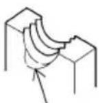
CAUTION
As shown in Fig. 20, if the cutters are combined in such a way that both side without the notch on the cutter or both notch sides are facing out, the pitch of the threads on the studs and the threads on the cutter will not be in agreement. This can cause damage to the cutter edge or cause wear to premature damage to the main unit.
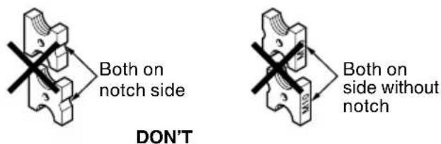
Fig. 20
(4) Attachment
① When using an M6, M8 or M10 cutter
Insert the cutter in the cutter attachment groove on the bracket, insert the special spacer between the cutter and the bracket and then use the hex. socket hd. bolt to tighten and secure.
② When using the W3/8" cutter
Insert the cutter in the cutter attachment groove on the bracket and then use the hex. socket hd. bolt to tighten and secure.
NOTE
Spacers are not required when using the W3/8" cutter.
CAUTION
The hex. socket hd. bolt should be sufficiently tightened with the hexagonal wrench.
| Size | Attachment | ||
| M10 |  | Hex. socket | 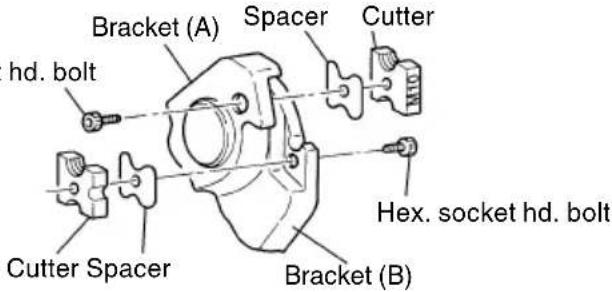 |
| M8 | 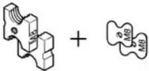 | ||
| M6 | 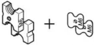 | ||
| W3/8" | 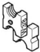 | Hex. socket hd. | 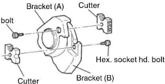 |
CAUTION
Use special cutters and spacers that conform with the size of the stud. Using cutters and spacers of the wrong size or confusing them can lead to damage to the stud and cutter.
MAINTENANCE AND INSPECTION
CAUTION
Be sure to remove the rechargeable battery from the unit during inspection and cleaning.
1. Care after use
After use, use a brush to brush off the work area, especially the area around the blade.
2. Inspecting the mounting screws
Regularly inspect all mounting screws and ensure that they are properly tightened. Should any of the screws be loose, retighten them immediately. Failure to could result in serious hazard.
3. Cleaning on the outside
When the power tool is stained, wipe with a soft dry cloth or a cloth moistened with soapy water. Do not use chloric solvents, gasoline or paint thinner, for they melt plastics.
4. Storage
Store the power tool in a place in which the temperature is less than 40^ C and out of reach of children.
NOTE
Storing lithium-ion batteries.
Make sure the lithium-ion batteries have been fully charged before storing them.
Prolonged storage (3 months or more) of batteries with a low charge may result in performance deterioration, signifi cantly reducing battery usage time or rendering the batteries incapable of holding a charge. However, signifi cantly reduced battery usage time may be recovered by repeatedly charging and using the batteries two to five times.
If the battery usage time is extremely short despite repeated charging and use, consider the batteries dead and purchase new batteries.
CAUTION
In the operation and maintenance of power tools, the safety regulations and standards prescribed in each country must be observed.
Important notice on the batteries for the HiKOKI cordless power tools
Please always use one of our designated genuine batteries. We cannot guarantee the safety and performance of our cordless power tool when used with batteries other than these designated by us, or when the battery is disassembled and modified (such as disassembly and replacement of cells or other internal parts).
GUARANTEE
We guarantee HiKOKI Power Tools in accordance with statutory/country specific regulation. This guarantee does not cover defects or damage due to misuse, abuse, or normal wear and tear. In case of complaint, please send the Power Tool, undismantled, with the GUARANTEE CERTIFICATE found at the end of this Handling instruction, to a HiKOKI Authorized Service Center.
NOTE
Due to HiKOKI's continuing program of research and development, the specifications herein are subject to change without prior notice.
Information concerning airborne noise and vibration
The measured values were determined according to EN62841 and declared in accordance with ISO 4871.
Measured A-weighted sound power level: 85 dB (A) Measured A-weighted sound pressure level: 74 dB (A) Uncertainty K: 1.5 dB (A).
Wear hearing protection.
Vibration total values (triax vector sum) determined according to EN62841.
Stud cutting:
Vibration emission value a_hV = 0.5 m/s^2
Uncertainty K = 1.5 m/s ^2
The declared vibration total value has been measured in accordance with a standard test method and may be used for comparing one tool with another.
It may also be used in a preliminary assessment of exposure.
WARNING
☐ The vibration emission during actual use of the power tool can differ from the declared total value depending on the ways in which the tool is used.
- Identify safety measures to protect the operator that are based on an estimation of exposure in the actual conditions of use (taking account of all parts of the operating cycle such as the times when the tool is switched off and when it is running idle in addition to the trigger time).
natural_image
Pure mechanical diagram showing a gear or cam mechanism without any text, numbers, or symbolsAbb. 17
Vibrationsemissionswert a_hv = 0.5 m/s^2
natural_image
Two technical line drawings of a power strip device (no text or symbols visible)(BSL1430, BSL1440, (BSL1830, BSL1840, BSL1450, BSL1460) BSL1850, BSL1860)
(BSL36..18)
- Cutter
| Dimension de vis Assemblage des cutters et entretoises | ||
| M10 × 1,5 M10 Cutter ..... | .....2M10 Entretoise .....2 | 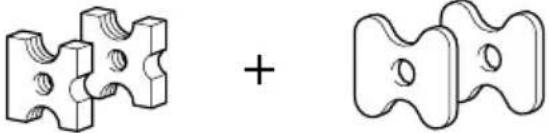 |
| M8 × 1,25 M8 Cutter ..... | .....2M8 Entretoise .....2 | |
| M6 × 1 M6 Cutter ..... | .....2M6 Entretoise .....2 | |
| W3/8" × 1,5875 W3/8" Cutter .....2 | 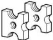 | |
- Ebarboir
| Dimension de vis |  |
| M10 × 1,5 | |
| M8 × 1,25 | |
| M6 × 1 | |
| W3/8" × 1,5875 |
natural_image
Pure mechanical diagram showing a gear or cam mechanism without any text, numbers, or symbolsFig. 17
natural_image
Pure mechanical diagram showing a gear or cam mechanism without any text, numbers, or symbolsFig. 17
natural_image
Pure mechanical diagram showing a gear or cam mechanism without any text, numbers, or symbolsAfb. 17
| Afmeting | Bevestiging | |
| M10 | 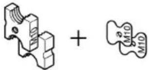 | 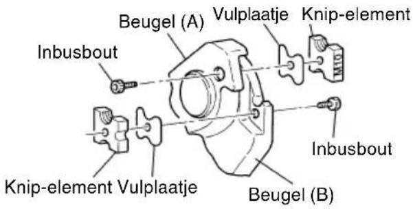 |
| M8 |  | |
| M6 | 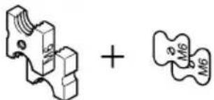 | |
| W3/8" |  | 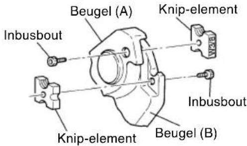 |
LET OP
natural_image
Technical line drawing of a mechanical component with motion arrows indicating movement (no text or symbols)Fig. 17
natural_image
Pure mechanical diagram showing a gear or cam mechanism without any text, numbers, or symbolsFig. 17
natural_image
Line drawing of a quill pen in an inkwell (no text or symbols)| English Nederlands | |||
| GUARANTEE CERTIFICATE1 Model No.2 Serial No.3 Date of Purchase4 Customer Name and Address5 Dealer Name and Address(Please stamp dealer name and address) | GARANTIEBEWIJS1 Modelnummer2 Serienummer3 Datum van aankoop4 Naam en adres van de gebruiker5 Naam en adres van de handelaar(Stempel a.u.b. naam en adres vande de handelaar) | ||
| Deutsch Español | |||
| GARANTIESCHEIN1 Modell-Nr.2 Serien-Nr.3 Kaufdatum4 Name und Anschrift des Kunden5 Name und Anschrift des Händlers(Bitte mit Namen und Anschrift des Handlers abstempeln) | CERTIFICADO DE GARANTIA1 Número de modelo2 Número de serie3 Fecha de adquisición4 Nombre y dirección del cliente5 Nombre y dirección del distribudor(Se ruega poner el sellú del distribudor con su nombre y dirección) | ||
| Français Português | |||
| CERTIFICAT DE GARANTIE1 No. de modèle2 No. de série3 Date d'achat4 Nom et adresse du client5 Nom et adresse du revendeur(Cachet portant le nom et l'adresse du revendeur) | CERTIFICADO DE GARANTIA1 Número do modelo2 Número do série3 Data de compra4 Nome e morada do cliente5 Nome e morada do distribuidor(Por favor, carímbe o nome e morada do distribuidor) | ||
| Italiano | |||
| CERTIFICATO DI GARANZIA1 Modello2 N° di serie3 Data di acquisto4 Nome e indirizzo dell'acquirente5 Nome e indirizzo del rivenditore(Si prega di apporre il timbro con questi dati) | |||
HiKOKI
| 1 | |
| 2 | |
| 3 | |
| 4 | |
| 5 |
Siemensring 34, 47877 willich, Germany
Tel: +49 2154 49930
Fax: +49 2154 499350
URL: http://www.hikoki-powertools.de
Hikoki Power Tools Netherlands B.V.
Brabanthaven 11, 3433 PJ Nieuwegein, The Netherlands
Tel: +31 30 6084040
Fax: +31 30 6067266
URL: http://www.hikoki-powertools.nl
Hikoki Power Tools (U.K.) Ltd.
Precedent Drive, Rooksley, Milton Keynes, MK 13, 8PJ,
United Kingdom
Tel: +44 1908 660663
Fax: +44 1908 606642
URL: http://www.hikoki-powertools.uk
Hikoki Power Tools France S.A.S.
Hikoki Power Tools Belgium N.V./S.A.
Koningin Astridlaan 51, B-1780 Wemmel, Belgium
Tel: +32 2 460 1720
Fax: +32 2 460 2542
URL http://www.hikoki-powertools.be
Hikoki Power Tools Italia S.p.A
Via Piave 35, 36077, Altavilla Vicentina (VI), Italy
Tel: +39 0444 548111
Fax: +39 0444 548110
URL: http://www.hikoki-powertools.it
Hikoki Power Tools Ibérica, S.A.
C/ Puigbarral, 26-28, Pol. Ind. Can Petit, 08227 Terrassa
(Barcelona), Spain
Tel: +34 93 735 6722
Fax: +34 93 735 7442
URL: http://www.hikoki-powertools.es

- GENERAL POWER TOOL SAFETY WARNINGS
- WARNING
- 1) Work area safety
- 2) Electrical safety
- 3) Personal safety
- 4) Power tool use and care
- PRECAUTION
- PRECAUTIONS FOR CORDLESS STUD CUTTER
- CAUTION ON LITHIUM-ION BATTERY
- SPECIFICATIONS
- CAUTION
- REGARDING LITHIUM-ION BATTERY TRANSPORTATION
- OPTIONAL ACCESSORIES (sold separately)
- Battery
- APPLICATIONS
- BATTERY REMOVAL/INSTALLATION
- Battery removal
- Battery installation
- CHARGING
- Connect the charger's power cord to a receptacle.
- Insert the battery into the charger.
- Charging
- Pilot lamp indication
- Regarding the temperatures and charging time of the battery.
- NOTE
- Regarding electric discharge in case of new batteries, etc.
- How to make the batteries perform longer
- PRIOR TO OPERATION
- Correctly insert the stud guide
- HOW TO USE
- Normal Cutting Method
- Number of cuttings (per battery charging)
- Cutting fixed lengths (Fig. 9)
- Cutting studs that are already secured (Fig. 10)
- Removing the screw from the unit during cutting operations
- Using the hook
- Using the trimmer
- About Remaining Battery Indicator
- CUTTER LIFE AND REPLACEMENT
- Cutter life
- Changing the cutter attachment direction or replacing the cutter
- Attachment
- MAINTENANCE AND INSPECTION
- Care after use
- Inspecting the mounting screws
- Cleaning on the outside
- Storage
- Important notice on the batteries for the HiKOKI cordless power tools
- GUARANTEE
- Information concerning airborne noise and vibration
- LET OP
- Hikoki Power Tools Netherlands B.V.
- Hikoki Power Tools (U.K.) Ltd.
- Hikoki Power Tools France S.A.S.
- Hikoki Power Tools Belgium N.V./S.A.
- Hikoki Power Tools Italia S.p.A
- Hikoki Power Tools Ibérica, S.A.
Brand : HiKOKI
Model : CL14DSL
Category : Scissors