VTP-18 - Drill HiKOKI - Free user manual and instructions
Find the device manual for free VTP-18 HiKOKI in PDF.

User questions about VTP-18 HiKOKI
0 question about this device. Answer the ones you know or ask your own.
Ask a new question about this device
Download the instructions for your Drill in PDF format for free! Find your manual VTP-18 - HiKOKI and take your electronic device back in hand. On this page are published all the documents necessary for the use of your device. VTP-18 by HiKOKI.
USER MANUAL VTP-18 HiKOKI
natural_image
Technical line drawing of a power drill with labeled component (VTP-18), no other text or symbols present.Read through carefully and understand these instructions before use. Diese Anleitung vor Benutzung des Werkzeugs sorgfältig durchlesen und verstehen. Lire soigneusement et bien assimiler ces instructions avant usage. Prima dell'uso leggere attentamente e comprendere queste istruzioni. Deze gebruiksaanwijzing s.v.p. voor gebruik zorgvuldig doorlezen. Leer cuidadosamente y comprender estas instrucciones antes del uso. Antes de usar, leia com cuidado para assimilar estas instruções. Διαβάστε προσεκτικά και κατανοήςετε αυτές τις οδηγίες πριν τη χρήση.

Handling instructions Bedienungsanleitung Mode d'emploi Istruzioni per l'uso Gebruiksaanwijzing Instrucciones de manejo Instruções de uso Οδηγίες χειριςμού
text_image
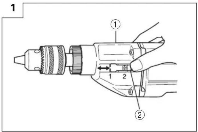
1 ① ② ① ②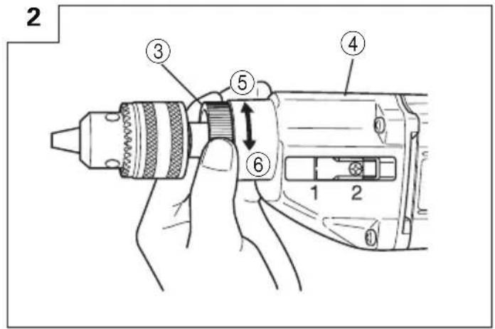
text_image
2 ③ ⑤ ④ ⑥ 1 2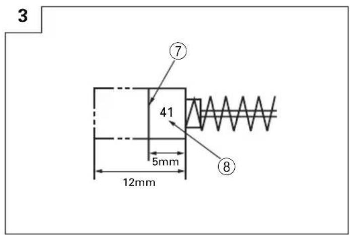
text_image
3 ⑦ 41 5mm 12mm ⑧
text_image
4 ⑨ ⑩ ⑪ ⑪ ⑫ ⑬ ⑬| English Deutsch | Français Italiano | |||
| 1 | Gear Cover Getriebekasten | Capot de l’engrenage | Coperchio degli ingranaggi | |
| 2 | Shift Lock Umschaltfeststellern(Push and Slide) (eindrücke und schieben) | Piéce de blocage coulissante (Pousser et faire coulisser) | Chiavetta a cursore (Prenere e spostare) | |
| 3 | Change Ring Stellring Bague de Commutation | Anello del cambio | ||
| 4 | Gear Cover Getriebekasten | Capot de l’engrenage | Coperchio degli ingranaggi | |
| 5 | Rotation Reine Bohrfunktion Rotation | Rotazione | ||
| 6 | Rotation+Impact Schlagbohrfunktion Rotation Percussion | Rotazione e impatto | ||
| 7 | Wear limit Verschleißgrenze Limit d’usure | Limite di usura | ||
| 8 | No. of carbon brush | Nr. der Kohlebürste | No. du balai en carbone | N. della spazzola di carbone |
| 9 | Brush Holder | Bürstenhalter | Support du balai | Porfa-spazzola |
| 10 | Holder Plate | Halteplatte | Plaque support | Piastrina di tenuta |
| 11 | Internal wiring | Interne Verdrahtung | Câblage interne | Fili interni |
| 12 | Switch | Schalter Interrupteur | Interruttore | |
| 13 | Carbon Brush | Kohlebürste | Balai en carbone | Spazzola di carbone |
| Nederlands Español | Português Ελληνικά | |||
| 1 | Aandrijfkast | Caja de engranaje | Capa de engrenagem | Κάλυμμα γραναζιών |
| 2 | Vastzetknop (indrukken en schuiven) | Cierre de traslación (presionary crrer) | Peça de bloqueio (empurrar e deslizar) | Μετατοπιζόμενη Κλειδαριά (Σπρώξτε και ολισθήστε) |
| 3 | Stelring | Anillo de alteración | Anel de comutação | Δακτύλιοσ αλλαγήσ |
| 4 | Aandrijfkast | Caja de engranaje | Capa da engrenagem | Κάλυμμα γραναζιών |
| 5 | Normale boorfunctie | Rotación | Rotação | Περιστροφή |
| 6 | Slagboorfunctie | Rotación+Impacto | Rotação+Impacto | Περιστροφή + Κρούση |
| 7 | Slijtagegrens Límite de uso | Límite de desgaste | Όριο Φθοράσ | |
| 8 | Nr. van de koolborstel | No. de carbón de contacto | No da escova de carvão | Αρ. καβουνακιού |
| 9 | Borstelhouder | Sujetador de carbón | Suporte da escova | Θήκη καρβουνακιού |
| 10 | Steunplaat | Placa de sujetador | Placa de suporte | Πλάκα στερέωσησ |
| 11 | Interne bedrading | Conducciones internas | Fiação interna | Εσωτερική καλωδίωση |
| 12 | Schakelaar | Pulsador | Interruptor | Διακόπτησ |
| 13 | Koolborstel Carbón de cotacto | Escova de carvão | Καρβουνάκι | |
GENERAL OPERATIONAL PRECAUTIONS
WARNING! When using electric tools, basic safety precautions should always be followed to reduce the risk of fire, electric shock and personal injury, including the following.
Read all these instructions before operating this product and save these instructions.
For safe operations:
- Keep work area clean. Cluttered areas and benches invite injuries.
- Consider work area environment. Do not expose power tools to rain. Do not use power tools in damp or wet locations. Keep work area well lit. Do not use power tools where there is risk to cause fire or explosion.
- Guard against electric shock. Avoid body contact with earthed or grounded surfaces. (e.g. pipes, radiators, ranges, refrigerators).
- Keep children away. Do not let visitors touch the tool or extension cord. All visitors should be kept away from work area.
- Store idle tools. When not in use, tools should be stored in a dry, high or locked up place, out of reach of children.
- Do not force the tool. It will do the job better and safer at the rate for which it was intended.
- Use the right tool. Do not force small tools or attachments to do the job of a heavy duty tool. Do not use tools for purposes not intended; for example, do not use circular saw to cut tree limbs or logs.
- Dress properly. Do not wear loose clothing or jewellery, they can be caught in moving parts. Rubber gloves and non-skid footwear are recommended when working outdoors. Wear protecting hair covering to contain long hair.
- Use eye protection. Also use face or dust mask if the cutting operation is dusty.
- Connect dust extraction equipment. If devices are provided for the connection of dust extraction and collection facilities ensure these are connected and properly used.
- Do not abuse the cord. Never carry the tool by the cord or yank it to disconnect it from the receptacle. Keep the cord away from heat, oil and sharp edges.
- Secure work. Use clamps or a vise to hold the work. It is safer than using your hand and it frees both hands to operate tool.
- Do not overreach. Keep proper footing and balance at all times.
- Maintain tools with care. Keep cutting tools sharp and clean for better and safer performance. Follow instructions for lubrication and changing accessories. Inspect tool cords periodically and if damaged, have it repaired by authorized service center. Inspect extension cords periodically and replace, if damaged. Keep handles dry, clean, and free from oil and grease.
-
Disconnect tools. When not in use, before servicing, and when changing accessories such as blades, bits and cutters.
-
Remove adjusting keys and wrenches. Form the habit of checking to see that keys and adjusting wrenches are removed from the tool before turning it on.
- Avoid unintentional starting. Do not carry a plugged-in tool with a finger on the switch. Ensure switch is off when plugging in.
- Use outdoor extension leads. When tool is used outdoors, use only extension cords intended for outdoor use.
- Stay alert. Watch what you are doing. Use common sense. Do not operate tool when you are tired.
- Check damaged parts. Before further use of the tool, a guard or other part that is damaged should be carefully checked to determine that it will operate properly and perform its intended function. Check for alignment of moving parts, free running of moving parts, breakage of parts, mounting and any other conditions that may affect its operation. A guard or other part that is damaged should be properly repaired or replaced by an authorized service center unless otherwise indicated in this handling instructions. Have defective switches replaced by an authorized service center. Do not use the tool if the switch does not turn it on and off.
- Warning The use of any accessory or attachment, other than those recommended in this handling instructions, may present a risk of personal injury.
- Have your tool repaired by a qualified person. This electric tool is in accordance with the relevant safety requirements. Repairs should only be carried out by qualified persons using original spare parts. Otherwise this may result in considerable danger to the user.
PRECAUTIONS ON USING IMPACT DRILL
- Before drilling into a wall, floor or ceiling, thoroughly confirm that no items such as electric cables or conduits are buried inside.
- Always hold the body handle and side handle of the power tool firmly. Otherwise the counterforce produced may result in inaccurate and even dangerous operation.
SPECIFICATIONS
| Model VTP-18 VTV-18 | ||||
| Voltage (by areas)* (110V, 115V, 120V, 127V, 220V, 230V, 240V) | ||||
| Power input 640W* | ||||
| Speed change 1 | 2 | 1 | 2 | |
| No-load speed | 1050/min | 1800/min | 0 – 1050/min | 0 – 1800/min |
| Capacity: Steel | 13mm | 8mm | 13mm | 8mm |
| Concrete | 18mm | 10mm | 18mm | 10mm |
| Weight (w/o cord) | 2.3 kg | |||
* Be sure to check the nameplate on product as it is subject to change by areas.
STANDARD ACCESSORIES
(1) Chuck Wrench .... 1
(2) Side Handle 1
(3) Depth Stopper 1
Standard accessories are subject to change without notice.
OPTIONAL ACCESSORIES (sold separately)
○Drill Bit for concrete
| O.D. Length Code No. | |
| 6.5mm 100mm 931851 | |
| 8.0 100 931852 | |
| 9.5 120 931853 | |
| 10.0 120 931854 | |
| 12.0 160 971704 | |
| 13.0 160 931855 | |
| 14.3 160 931776 | |
| 16.0 160 971670 | |
| 18.0 300 950496 |
Optional accessories are subject to change without notice.
APPLICATIONS
○By combined action of ROTATION and IMPACT:
Boring, holes in concrete, marble, granite, tile and similar materials.
○By ROTATION only:
Boring holes in metals, wood and plastics.
PRIOR TO OPERATION
1. Power source
Ensure that the power source to be utilized conforms to the power requirements specified on the product nameplate.
2. Power switch
Ensure that the power switch is in the OFF position. If the plug is connected to a receptacle while the power switch is in the ON position, the power tool
will start operating immediately, which could cause serious injury.
3. Extension cord
When the work area is not near a power source. Use an extension cord of sufficient thickness and rated capacity. The extension cord should be kept as short as possible.
4. Fitting the Drill Bit:
Fit the drill bit into the chuck and use the chuck wrench to secure it, tightening the chuck by each of the three holes in turn.
5. Selecting the appropriate drill bit:
○When boring concrete or stone:
Use the drill bits specified in the Optional Accessories.
○When boring metal or plastic:
Use an ordinary metalworking drill bit.
○When boring wood:
Use an ordinary woodworking drill bit. However, when drilling. 6.5mm or smaller holes, use a metalworking drill bit.
6. High-speed/Low-speed changeover:
Prior to changing speed, ensure that the switch is in the OFF position, and the drill has come to a complete stop. To change speed, depress the shift lock and slide it in the appropriate direction, as indicated by the arrow in Fig. 1. The numeral "1" engraved in the drill body denotes low speed, the numeral "2" denotes high speed.
7. IMPACT to ROTATION changeover: (Fig. 2)
The Impact Drill can be switched from IMPACT (impact plus rotation) to ROTATION (rotation only) by simply turning the change ring.
When boring concrete, stone, tile or similar hard materials, turn the change ring fully clockwise when viewed from the drill chuck side. The drill head impacts against the material while continuing to rotate.
When boring metal, wood or plastic, turn the change ring fully counterclockwise. The drill simply rotates as an ordinary electric drill.
CAUTION
Do not use the Impact Drill in the IMPACT function if the material can be bored by rotation only. Such action will not only reduce drilling efficiency, but may also damage the drill tip.
When changing over, ensure that the change ring is turned as far as it will go.
8. Fixing the side handle:
Loosen the knob bolt on the side handle, and attach the side handle to the gear cover in a position convenient for drilling.
Match the projecting part of the handle to the groove on the gear cover, and firmly tighten the knob bolt. To remove the side handle, loosen the knob bolt and rotate the handle.
To attach a depth stopper on the side handle, insert the depth stopper into the U-shaped groove on the side handle, adjust the position of the depth stopper in accordance with the desired depth of the hole, and firmly tighten the knob bolt.
PRACTICAL HANDLING PROCEDURES
1. Pressure:
Drilling will NOT be accelerated by placing heavy pressure on the drill. Such action will only result in a damaged drill bit, decreased drilling efficiency, and/or shortened service life of the drill.
2. Using a large diameter drill bit:
When using the larger diameter drill bit, the larger reactive force is applied on your arm. Be careful not to lose control of the drill because of this reactive force. To maintain firm control, establish a good foothold, hold the drill tightly with both hands, and ensure that the drill is vertical to the material being drilled.
3. When drilling completely through the material:
When the drill bit bores completely through the material, careless handling often results in a broken drill bit or damage to the drill body itself due to the sudden movement of the drill.
Always be alert and ready to release the pushing force when penetrating the material.
4. Switch operation:
(1) VTP-18 :
By pulling the trigger switch and depressing the stopper, the switch is held in the ON position for continuous operation. To turn the drill OFF, pull the trigger switch again and release.
(2) VTV-18 :
The rotational speed of the drill bit can be controlled by varying the amount that the trigger switch is pulled. Speed is low when the trigger switch is pulled slightly and increases as the switch is pulled more. Continuous operation may be attained by pulling the trigger switch and depressing the stopper. To turn the switch OFF, pull the trigger switch again to disengage the stopper, and release the trigger switch to its original position.
5. Precautions on Boring
The drill bit may become overheated during operation; however, it is sufficiently operable. Do not cool the drill bit in water or oil.
6. Caution concerning immediately after use
Immediately after use, while it is still revolving, if the Drill is placed on a location where considerable ground chips and dust have accumulated, dust may occasionally be absorbed into the Drill mechanism. Always pay attention to this possibility.
MAINTENANCE AND INSPECTION
1. Inspecting the Drill Bit:
Continued use of a worn and/or damaged drill bit will result in reduced drilling efficiency and may seriously overload the drill motor. Inspect the drill bit often and replace it with a new bit as necessary.
2. Inspecting the mounting screws:
Regularly inspect all mounting screws and ensure that they are properly tightened. Should any of the screws be loose, retighten them immediately. Failure to do so could result in serious hazard.
3. Inspecting the carbon brushes (Fig. 3)
The motor employs carbon brushes which are consumable parts. Since excessively worn carbon brushes can result in motor trouble, replace the carbon brushes with new ones having the same carbon brush No. shown in the figure when they become worn to or near the "wear limit". In addition, always keep carbon brushes clean and ensure that they slide freely within the brush holders.
4. Replacing carbon brushes:
○Disassembling:
(1) Loosen the three screws on the handle cover, and remove the handle cover. Remove the holder plates, which keeps the brush holders in place, by removing the stopper screws.
(2) Lift out the brush holders together with the carbon brushes, while being very careful not to forcibly pull the lead wires within the brush holders.
(3) Withdraw the brush terminals, and remove the carbon brushes from the brush holders.
○Reassembling:
(1) Place new carbon brushes into the brush holders, and connect the brush terminals to the carbon brushes.
(2) Return the brush holders and other parts to their original positions, as illustrated in Fig. 4, press the holder plates into position, and fasten it with the stopper screws.
(3) Place the lead wire in the specified position.
Be very careful not to allow the lead wire to contact the armature or rotating parts of the motor.
(4) Replace the handle cover, while being careful to ensure it does not pinch the lead wire, and secure it firmly with the three screws.
CAUTION
Should the lead wire be pinched by the handle cover or come in contact with the armature or rotating parts of the motor, a serious danger of electric shock to the operator will be created. Exercise extreme caution in disassembling and reassembling the motor, follow the above procedure exactly.
DO NOT attempt to disassemble any parts other than those necessary to effect replacement of the carbon brushes.
5. Maintenance of the motor
The motor unit winding is the very "heart" of the power tool.
Exercise due care to ensure the winding does not become damaged and/or wet with oil or water.
6. Service parts list
A: Item No.
B: Code No.
C: No. Used
D: Remarks
CAUTION
Repair, modification and inspection of HiKOKI Power Tools must be carried out by an HiKOKI Authorized Service Center.
This Parts List will be helpful if presented with the tool to the HiKOKI authorized Service Center when requesting repair or other maintenance.
In the operation and maintenance of power tools, the safety regulations and standards prescribed in each country must be observed.
MODIFICATION
HiKOKI Power Tools are constantly being improved and modified to incorporate the latest technological advancements.
Accordingly, some parts (i.e. code numbers and/or design) may be changed without prior notice.
NOTE
Due to HiKOKI's continuing program of research and development, the specifications herein are subject to change without prior notice.
IMPORTANT
Correct connection of the plug
The wires of the main lead are coloured in accordance with the following code:
Blue: — Neutral
Brown: — Live
As the colours of the wires in the main lead of this tool may not correspond with the coloured markings identifying the terminals in your plug proceed as follows:
The wire coloured blue must be connected to the terminal marked with the letter N or coloured black.
The wire coloured brown must be connected to the terminal marked with the letter L or coloured red.
Neither core must be connected to the earth terminal.
NOTE
This requirement is provided according to BRITISH STANDARD 2769: 1984.
Therefore, the letter code and colour code may not be applicable to other markets except The United Kingdom.
Information concerning airborne noise and vibration
The measured values were determined according to EN50144-2-1: 1995
The typical A-weighted sound pressure level: 102dB (A).
The typical A-weighted sound power level: 111dB (A).
Use ear protection.
The typical weighted root mean square acceleration value: 9.5 m/s^2 .
text_image
Exploded view diagram of a mechanical assembly with numbered parts for identificationVTV-18
| A | B | C | D | A | B | C | D |
| 1 930-515 | 1 10G | 42 1 316-257 | 1 | ||||
| 2 950-272 | 1 13VLA "1" | 42 2 307-893 | 1 "GBR(110V)" | ||||
| 3 948-001 | 1 | 43 954-004 | 2 D4×16 | ||||
| 4 971-654 | 1 | 44 971-655 | 2 | ||||
| 5 980-191 | 1 | 45 999-041 | 2 | ||||
| 6 600-2DD | 1 | 6002DDUCMPS2S | 46 955-203 | 2 | |||
| 7 997-497 | 1 | 47 —— | 1 | ||||
| 8 980-194 | 1 | 48 949-554 | 2 M4 | ||||
| 9 939-542 | 1 | 49 —— | 1 | ||||
| 10 971-645 | 1 | 50 981-373 | 1 | ||||
| 11 872-767 | 1 S-32 | 51 980-063 | 1 | ||||
| 12 953-038 | 1 | 52 981-373 | 1 | ||||
| 13 971-644 | 1 | 53 994-273 | 1 | ||||
| 14 301-654 | 4 D5×35 | 54 930-153 | 1 | ||||
| 15 980-172 | 1 | 55 984-750 | 2 D4×16 | ||||
| 16 971-656 | 1 | 56 937-631 | 1 | ||||
| 17 971-657 | 1 | 57 1 307-217 | 1 D7.2 | ||||
| 18 971-664 | 1 | 57 2 303-662 | 1 D8.8 | ||||
| 19 608-VVM | 1 | 608VVMC2EPS2L | 58 981-373 | 2 | |||
| 20 971-659 | 1 | 501 971-662 | 1 | ||||
| 21 1 971-666C | 1 110V-127V | 502 971-677 | 1 | ||||
| 21 2 971-666E | 1 220V-230V | 503 310-904 | 1 | ||||
| 22 971-642 | 1 | ||||||
| 23 1 971-665Z | 1 | 110V "38" | |||||
| 23 2 971-665G | 1 | 220V-230V "38" | |||||
| 24 608-VVM | 2 | 608VVMC2EPS2L | |||||
| 25 946-362 | 1 | ||||||
| 26 316-256 | 1 | ||||||
| 27 —— | 1 | ||||||
| 28 306-729 | 1 M14×12 | ||||||
| 29 949-535 | 1 D3×12 | ||||||
| 30 971-653 | 1 | ||||||
| 31 943-053 | 1 | ||||||
| 32 316-254 | 1 | ||||||
| 33 971-672 | 1 | ||||||
| 34 971-651 | 1 | ||||||
| 35 971-649 | 1 | ||||||
| 36 990-430 | 2 M4×10 | ||||||
| 37 949-278 | 2 M4×55 | ||||||
| 38 949-454 | 2 M5 | ||||||
| 39 981-373 | 1 | ||||||
| 40 301-653 | 3 D4×20 | ||||||
| 41 984-221 | 1 |
| English | Nederlands | ||
| GUARANTEE CERTIFICATE1Model No.2Serial No.3Date of Purchase4Customer Name and Address5Dealer Name and Address(Please stamp dealer name and address) | GARANTIEBEWIJS1Modelnummer2Serienummer3Datum van aankoop4Naam en adres van de gebruiker5Naam en adres van de handelaar(Stempel a.u.b. naam en adres vande de handelaar) | ||
| Deutsch | GARANTIESCHEIN1Modell-Nr.2Serien-Nr.3Kaufdaturn4Name und Anschrift des Kunden5Name und Anschrift des Händlers(Bitte mit Namen und Anschrift des Handlers abstempeln) | Español | |
| CERTIFICADO DE GARANTIA1Número de modelo2Mùmero de serie3Fecha de adquisición4Nombre y dirección del cliente5 Nombre y dirección del distribudor(Se ruega poner el sellú del distribudor con su nombre y dirección) | |||
| Français | CERTIFICAT DE GARANTIE1No. de modèle2No de série3Date d'achat4Nom et adresse du client5Nom et adresse du revendeur(Cachet portant le nom et l'adresse du revendeur) | Português | |
| CETTIFICADO DE GARANTIA1Número do modelo2Número do série3Data de compra4Nome e morada do cliente5Nome e morada do distribuidor(Por favor, carímbe o nome e morada do distribuidor) | |||
| Italiano Ελληνικά | |||
| CERTIFICATO DI GARANZIA1Modello2N° di serie3Data di acquisto4Nome e indirizzo dell'acquirente5Nome e indirizzo del rivenditore(Si prega di apporre il timbro con questi dati) | ΠΙΣΤΟΠΟΙΗΤΙΚΟ ΕΓΓΥΗΣΗΣ1Αρ. Μοντέλου2Αὐξων Αρ.3Ημερομηνία αγοράς4 ́Όνομα και διεύθυνση πελάτη5 ́Όνομα και διεύθυνση μεταπωλητή(Παρακαλούμε να χρησιμοποιηθεί σφραγίδα) | ||
HiKOKI
| 1 | |
| 2 | |
| 3 | |
| 4 | |
| 5 |