
C12LCH - Saw HiKOKI - Free user manual and instructions
Find the device manual for free C12LCH HiKOKI in PDF.

| Product Type | Compound Miter Saw |
| Brand | HiKOKI |
| Model | C12LCH / C12FCH |
| Dimensions (L x W x H) | 625 mm x 775 mm x 610 mm |
| Weight | 19.5 kg (C12LCH) / 19 kg (C12FCH) |
| Power Supply | 220 V ~ 50/60 Hz |
| Power Consumption | 1520 W |
| No-load Speed | 4000 rpm |
| Blade Diameter | 305 mm (max 305 mm, min 290 mm) |
| Blade Bore | 25.4 mm |
| Blade Thickness | 2.7 mm |
| Cutting Capacity at 0° (H x W) | 63.5 mm x 200 mm or 98 mm x 155 mm |
| Cutting Capacity at 45° Miter (H x W) | 63.5 mm x 140 mm |
| Cutting Capacity at 45° Left Bevel (H x W) | 42 mm x 200 mm |
| Compound Cutting Capacity (Bevel 45°, Miter 45°) | 42 mm x 140 mm |
| Miter Angle Range | 0° – 52° right and left |
| Bevel Angle Range | -3° – 48° left |
| Digital Display | Yes, accurate to ±0.5° (C12LCH model) |
| Laser Marker | Yes, Class II, 654 nm, < 3 mW |
| Included Accessories | TCT blade 305 mm, dust bag, 17 mm socket wrench, vice, 4 mm hex wrench |
| Maintenance and Cleaning | Monthly lubrication of sliding surfaces; regular cleaning of lower guard; replace worn carbon brushes; entrust repairs to a HiKOKI authorized service center |
| Safety | Moving lower guard, motor stop, trigger lock, circuit breaker |
Frequently Asked Questions - C12LCH HiKOKI
User questions about C12LCH HiKOKI
0 question about this device. Answer the ones you know or ask your own.
Ask a new question about this device
Download the instructions for your Saw in PDF format for free! Find your manual C12LCH - HiKOKI and take your electronic device back in hand. On this page are published all the documents necessary for the use of your device. C12LCH by HiKOKI.
USER MANUAL C12LCH HiKOKI
natural_image
Technical line drawing of a mechanical device with a circular frame (no text or symbols)保留备用
Keep for future reference

使用说明书
Handling instructions

目次
natural_image
Technical line drawing of a mechanical assembly with no visible text or symbols图9
图12
注意!
natural_image
Technical line drawing of a mechanical component with no visible text or symbols图15
注意!
OPTIONAL ACCESSORIES (sold separately)......40
APPLICATION 40
UNPACKING 40
PRACTICAL APPLICATIONS 41
MOUNTING AND DISMOUNTING SAW BLADE ....50
MAINTENANCE AND INSPECTION 52
SERVICE PARTS LIST 55
GENERAL OPERATIONAL PRECAUTIONS
WARNING!
When using electric tools, basic safety precautions should always be followed to reduce the risk of fire, electric shock and personal injury, including the following.
Read all these instructions before operating this product and save these instructions. For safe operations:
-
Keep work area clean. Cluttered areas and benches invite injuries.
-
Consider work area environment. Do not expose power tools to rain. Do not use power tools in damp or wet locations. Keep work area well lit. Do not use power tools where there is risk to cause fire or explosion.
-
Guard against electric shock. Avoid body contact with earthed or grounded surfaces (e.g. pipes, radiators, ranges, refrigerators).
-
Keep children and infirm persons away. Do not let visitors touch the tool or extension cord. All visitors should be kept away from work area.
-
Store idle tools. When not in use, tools should be stored in a dry, high or locked up place, out of reach of children and infi rm persons.
-
Do not force the tool. It will do the job better and safer at the rate for which it was intended.
-
Use the right tool. Do not force small tools or attachments to do the job of a heavy duty tool. Do not use tools for purposes not intended; for example, do not use circular saw to cut tree limbs or logs.
-
Dress properly. Do not wear loose clothing or jewelry, they can be caught in moving parts. Rubber gloves and non-skid footwear are recommended when working outdoors. Wear protecting hair covering to contain long hair.
-
Use eye protection. Also use face or dust mask if the cutting operation is dusty.
-
Connect dust extraction equipment.
Cutting operation by this compound miter saw may produce considerable amount of dust from extraction duct on fi xed guard.
(Dust material: Wood or Aluminium)
If devices are provided for the connection of dust extraction and collection facilities ensure these are connected and properly used.
-
Do not abuse the cord. Never carry the tool by the cord or yank it to disconnect it from the receptacle. Keep the cord away from heat, oil and sharp edges.
-
Secure work. Use clamps or a vise to hold the work. It is safer than using your hand and it frees both hands to operate tool.
-
Do not overreach. Keep proper footing and balance at all times.
-
Maintain tools with care. Keep cutting tools sharp and clean for better and safer performance. Follow instructions for lubrication and changing accessories. Inspect tool cords periodically and if damaged, have it repaired by authorized service center. Inspect extension cords periodically and replace, if damaged. Keep handles dry, clean, and free from oil and grease.
-
Disconnect tools. When not in use, before servicing, and when changing accessories such as blades, bits and cutters.
-
Remove adjusting keys and wrenches. Form the habit of checking to see that keys and adjusting wrenches are removed from the tool before turning it on.
-
Avoid unintentional starting. Do not carry a plugged-in tool with a finger on the switch. Ensure switch is off when plugging in.
-
Use outdoor extension leads. When tool is used outdoors, use only extension cords intended for outdoor use.
-
Stay alert. Watch what you are doing. Use common sense. Do not operate tool when you are tired.
-
Check damaged parts. Before further use of the tool, a guard or other part that is damaged should be carefully checked to determine that it will operate properly and perform its intended function. Check for alignment of moving parts, free running of moving parts, breakage of parts, mounting and any other conditions that may affect its operation. A guard or other part that is damaged should be properly repaired or replaced by an authorized service center unless otherwise indicated in this handling instructions. Have defective switches replaced by an authorized service center. Do not use the tool if the switch does not turn it on and off.
-
Warning
The use of any accessory or attachment, other than those recommended in this handling instructions, may present a risk of personal injury.
- Have your tool repaired by a qualified person.
This electric tool is in accordance with the relevant safety requirements. Repairs should only be carried out by qualified persons using original spare parts. Otherwise this may result in considerable danger to the user.
PRECAUTIONS ON USING COMPOUND MITER SAW
- Keep the floor area around the machine level. Well maintained and free of loose materials e.g. chips and cut-off s.
- Provide adequate general or localized lighting.
- Do not use power tools for applications other than those specified in the handling instructions.
- Repairing must be done only by authorized service facility. Manufacturer is not responsible for any damages and injuries due to the repair by the unauthorized persons as well as the mishandling of the tool.
- To ensure the designed operational integrity of power tools, do not remove installed covers or screws.
- Do not touch movable parts or accessories unless the power source has been disconnected.
- Use your tool at lower input than specified on the nameplate; otherwise, the finish may be spoiled and working efficiency reduced due to motor overload.
- Do not wipe plastic parts with solvent. Solvents such as gasoline, thinner, benzine, carbon tetrachloride, alcohol, may damage and crack plastic parts. Do not wipe them with such solvent. Clean plastic parts with a soft cloth lightly dampened with soapy water.
- Use only original HiKOKI replacement parts.
- This tool should only be disassembled for replacement of carbon brushes.
- The exploded assembly drawing on this handling instructions should be used only for authorized service facility.
- Never cut ferrous metals or masonry.
- Adequate general or localized lighting is provided. Stock and finished workpieces are located close to the operators normal working position.
- Wear suitable personal protective equipment when necessary, this could include:
Hearing protection to reduce the risk of induced hearing loss.
Eye protection to reduce the risk of injuring an eye.
Respiratory protection to reduce the risk of inhalation of harmful dust.
Gloves for handling saw blades (saw blades shall be carried in a holder wherever practicable) and rough material. - The operator is adequately trained in the use, adjustment and operation of the machine.
- Refrain from removing any cut-offs or other parts of the workpiece from the cutting area whilst the machine is running and the saw head is not in the rest position.
- Never use the compound miter saw with its lower guard locked in the open position.
- Ensure that the lower guard moves smoothly.
- Do not use the saw without guards in position, in good working order and properly maintained.
- Use correctly sharpened saw blades. Observe the maximum speed marked on the saw blade.
-
Do not use saw blades which are damaged or deformed.
-
Do not use saw blades manufactured from high speed steel.
-
Use only saw blades recommended by HiKOKI.
-
The saw blades should be from 290 mm to 305 mm external diameter ranges.
-
Select the correct saw blade for the material to be cut.
-
Never operate the compound miter saw with the saw blade turned upward or to the side.
-
Ensure that the workpiece is free of foreign matter such as nails.
-
Replace the table insert when worn.
-
Do not use the saw to cut other than aluminium, wood or similar materials.
-
Do not use the saw to cut other materials than those recommended by the manufacturer.
-
Blade replacement procedure, including the method for repositioning and a warning that this must be carried out correctly.
-
Connect the compound miter saw to a dust collecting device when sawing wood.
-
Take care when slotting.
-
When transporting or carrying the tool, do not grasp the holder. Grasp the handle instead of the holder.
-
Start cutting only after motor revolution reaches maximum speed.
-
Promptly cut OFF the switch when abnormality observed.
-
Shut off power and wait for saw blade to stop before servicing or adjusting tool.
-
During a miter or bevel cut the blade should not be lifted until it has stopped rotation completely.
-
Take all the possibility of residual risks in cutting operation into your consideration, such as the laser radiation to your eyes, the inadvertent access to moving parts on slide mechanical parts on machine and so on.
SYMBOL
WARNING
The following show symbols used for the machine. Be sure that you understand their meaning before use.

To reduce the risk of injury, user must read instruction manual.
NAME OF PARTS
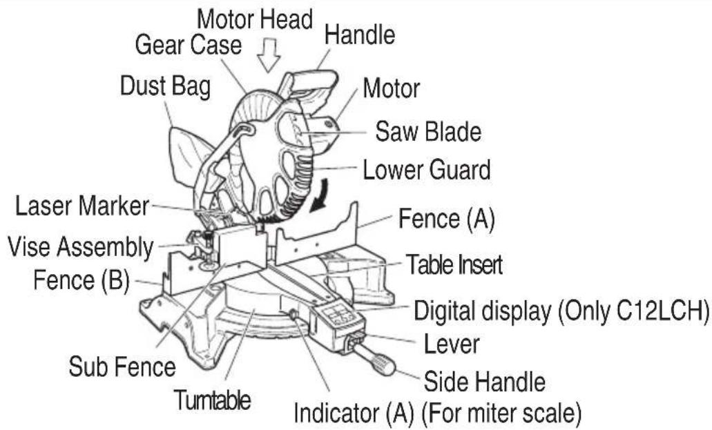
Fig. 1
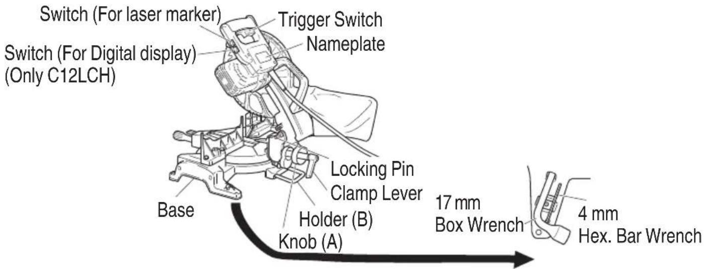
Fig. 2
SPECIFICATIONS
| Max. Cutting Capacity Height × Width | 0° | 63.5 mm × 200 mm or 98 mm × 155 mm | |
| Miter 45° 63.5 mm × 140 mm | |||
| Bevel Left 45° 42 mm × 200 mm | |||
| Compound (Bevel Left 45°, Miter 45°) 42 mm × 140 mm | |||
| Saw Blade Dimensions (oD × iD × Thickness) 305 mm × 25.4 mm × 2.7 mm | |||
| Miter Cutting Angle Right and Left 0° – 52° | |||
| Bevel Cutting Angle Left | -3° – 48° | ||
| Compound Cutting Angle | Miter (Right and Left) 0° – 45° Bevel (Left) 0° – 45° | ||
| Voltage | 220V~ | ||
| Power Input 1520 W | |||
| No-Load Speed 4000 /min | |||
| Machine Dimensions (Width × Depth × Height) 625 mm × 775 mm × 610 mm | |||
| Weight (Net) 19.5 kg (C12LCH) / 19 kg (C12FCH) | |||
| Digital Display (Only Model C12LCH) | Precision ±0.5° | ||
| Laser Marker | Maximum output | Po<3 mW Class II Laser Product | |
| (lambda) 654 nm | |||
| Laser medium | Laser Diode | ||
STANDARD ACCESSORIES
In addition to the main unit (1 unit), the package contains the accessories listed in the below.
| 305 mm TCT Saw blade (mounted on tool) | 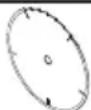 | 1 |
| Dust bag | 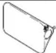 | 1 |
| 17 mm Box wrench | 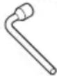 | 1 |
| Vise Assembly | 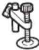 | 1 |
| 4 mm Hex. bar wrench | 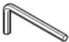 | 1 |
OPTIONAL ACCESSORIES (sold separately)
| (1) Extension Holder and Stopper | 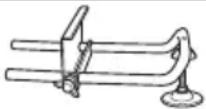 |
| (2) Crown molding Vise Ass'y (Include Crown molding Stopper (L)) |  |
| (3) Crown molding Stopper (L) |  |
| (4) Crown molding Stopper (R) | 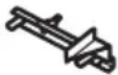 |
APPLICATION
○ Cutting various types of aluminium sash and wood.
UNPACKING
○ Carefully unpack the power tool and all related items (standard accessories).
☐ Check carefully to make certain all related items (standard accessories) are present.
PRIOR TO OPERATION
- Power source
Ensure that the power source to be utilized conforms to the power requirements specified on the product nameplate.
- Power switch
Ensure that the power switch is in the OFF position. If the plug is connected to a receptacle while the trigger switch is in the ON position, the power tool will start operating immediately, inviting serious accident.
- Extension cord
When the work area is removed from the power source, use an extension cord of sufficient thickness and rated capacity. The extension cord should be kept as short as practicable.
- When the power tool is prepared for shipping, its main parts are secured by a locking pin
Move the handle slightly so that the locking pin can be disengaged.
During transport, lock the locking pin into the gear case (Fig. 3).
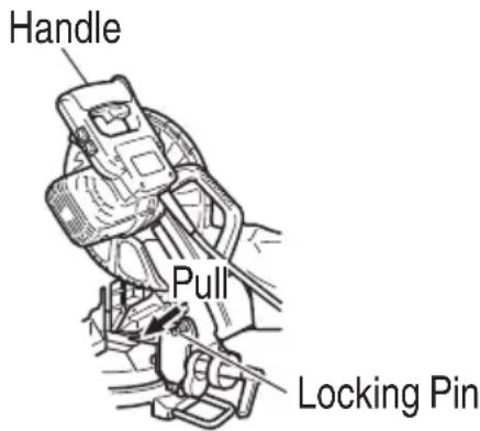
Fig. 3
- Attach the dust bag to the main unit (Fig. 1 on page 38)
(1) When the dust bag has become full of sawdust, dust will be blown out of the dust bag when the saw blade rotates.
Check the dust bag periodically and empty it before it becomes full.
(2) During bevel and compound cutting, attach the dust bag at a right angle to the base surface as shown in Fig. 4.
CAUTION
Empty the dust bag frequently to prevent the duct and the lower guard from becoming clogged.
Sawdust will accumulate more quickly than normal during bevel cutting.
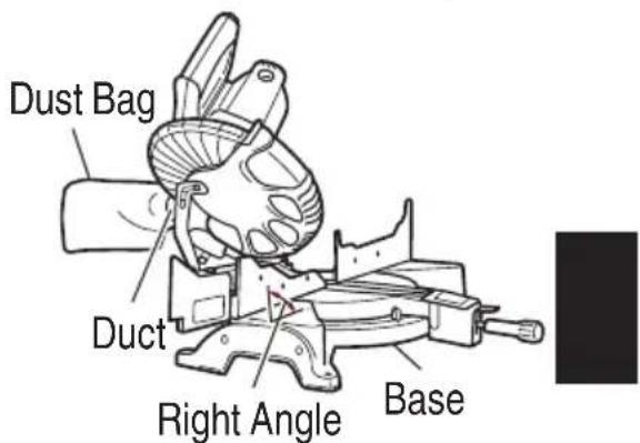
Fig. 4
- Installation
Ensure that the machine is always fixed to bench.
Attach the power tool to a level, horizontal work bench.
Select 8 mm diameter bolts suitable in length for the thickness of the work bench.
Bolt length should be at least 35 mm plus the thickness of the work bench.
For example, use 8 mm × 60 mm bolts for a 25 mm thick work bench.
ADJUSTING THE POWER TOOL PRIOR TO USE
CAUTION
Make all necessary adjustments before inserting the plug in the power source.
- Check to see that the lower guard operates smoothly
PRACTICAL APPLICATIONS
WARNING
○ To avoid personal injury, never remove or place a workpiece on the table while the tool is being operated.
Never place your limbs inside of the line next to warning sign while the tool is being operated. This may cause hazardous conditions (see Fig. 5).

Fig. 5
CAUTION
○ It is dangerous to remove or install the workpiece while the saw blade is turning.
When sawing, clean off the shavings from the turntable.
○ If the shavings accumulate too much, the saw blade from the cutting material will be exposed. Never subject your hand or anything else to go near the exposed blade.
-
Tightly secure the material by vise assembly to be cut so that it does not move during cutting
-
Switch operation Pulling the trigger turns the switch on. Releasing the trigger turns the switch off.
English
3. Holder (B) adjustment (Fig. 6)
Loosen the 6 mm bolt with the supplied 10 mm box wrench. Adjust the holder (B) until its bottom surface contacts the bench or the floor surface.
4. Using the Vise Assembly (Standard accessory) (Fig. 7)
(1) The vise assembly can be mounted on either the left fence {Fence (B)} or the right fence {Fence (A)} by loosening the 6 mm wing bolt (A).
(2) The screw holder can be raised or lowered according to the height of the workpiece by loosening the 6 mm wing bolt (B). After the adjustment, firmly tighten the 6 mm wing bolt (B) and fix the screw holder.
(3) Turn the upper knob and securely fix the workpiece in position.
WARNING
Always firmly clamp or vise to secure the workpiece to the fence; otherwise the workpiece might be thrust from the table and cause bodily harm.
CAUTION
Always confi rm that the motor head does not contact the vise assembly when it is lowered for cutting. If there is any danger that it may do so, loosen the 6 mm wing bolt and move the vise assembly to a position where it will not contact the saw blade.
5. Confirmation for use of sub fence (Fig. 8)
This power tool is equipped with a sub fence. In the case of direct angle cutting use the sub fence. Then, you can realize stable cutting of the material with a wide back face. In the case of left bavel cutting, raise the sub fence up as illustrated in Fig. 8 and then turn it counterclockwise.
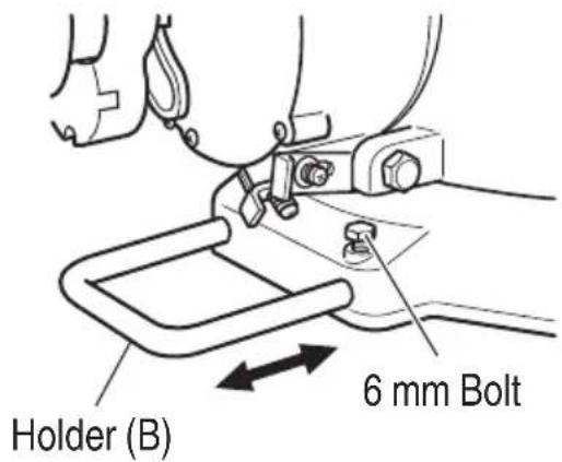
Fig. 6
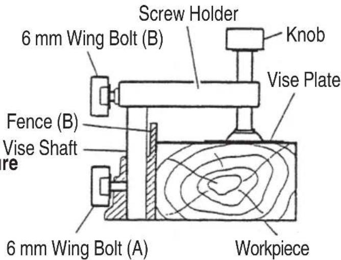
Fig. 7
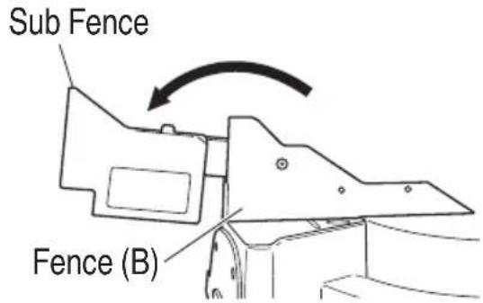
Fig. 8
WARNING
In the case of left bevel cutting, turn the sub fence counterclockwise (Fig. 8).
Unless it is turned counterclockwise, the main body or saw blade may contact the sub fence, resulting in an injury.
6. Using an ink line
Upon lowering the motor section, the lower guard is raised and the saw blade appears.
Align the ink line with the saw blade.
CAUTION
Never lift the lower guard while the saw blade is rotating.
The sub fence will not only make contact and adversely affect cutting accuracy, this could also result in damage to the guard.
7. Position adjustment of laser line
Ink lining can be easily made on this tool to the laser marker. A switch lights up the laser marker (Fig. 9).
Turning on the laser marker switch while the digital display switch is on, light up the laser marker. (On the C12FCH, only the laser marker switch.)
Depending upon your cutting choice, the laser line can be aligned with the left side of the cutting width (saw blade) or the ink line on the right side.
Switch
(For laser marker)
Switch
(For Digital display)
(Only C12LCH)
natural_image
Technical line drawing of a mechanical assembly with no visible text or symbolsFig. 9
The laser line is adjusted to the width of the saw blade at the time of factory shipment.
Adjust the positions of the saw blade and the laser line taking the following steps to suit the use of your choice.
(1) Light up the laser marker and make a groove of about 5 ~mm deep on the workpiece that is about 38 ~mm in height and 89 ~mm in width. Hold the grooved workpiece by vise as it is and do not move it.
(2) Then insert a 4 mm hex. bar wrench in the 12 diameter hole on the side of the gear case, turn the hex. socket set screw to move the laser line. (If you turn the Hex. socket screw clockwise, the laser line will shift to the right and if you turn it counterclockwise, the laser line will shift to the left.) When you work with the ink line aligned with the left side of the saw blade, align the laser line with the left end of the groove (Fig. 10). When you align it with the right side of the saw blade, align the laser line with the right side of the groove.
(3) After adjusting the position of the laser line, draw a right-angle ink line on the workpiece and align the ink line with the laser line. When aligning the ink line, slide the workpiece little by little and secure it by vise at a position where the laser line overlaps with the ink line. Work on the grooving again and check the position of the laser line. If you wish to change the laser line's position, make adjustments again following the steps from (1) to (3).
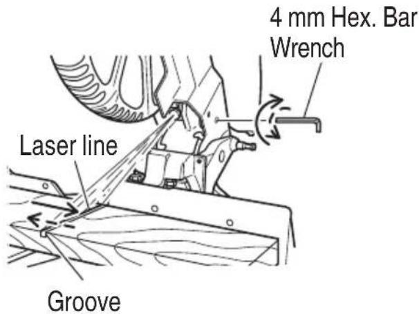
Fig. 10
English
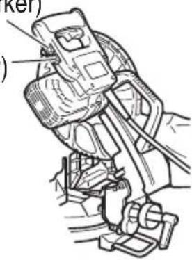
WARNING (Fig. 11 and Fig. 12)
○ Make sure before plugging the power plug into the receptacle that the main body and the laser marker are turned off.
Exercise utmost caution in handling a switch trigger for the position adjustment of the laser line, as the power plug is plugged into the receptacle during operation.
If the switch trigger is pulled inadvertently, the saw blade can rotate and result in unexpected accidents.
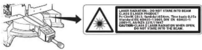
Fig. 11
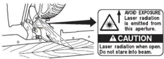
Fig. 12
○ Do not remove the laser marker to be used for other purposes.
CAUTION
○ Laser radiation - Do not stare into beam.
○ Laser radiation on work table. Do not stare into beam. If your eye is exposed directly to the laser beam, it can be hurt.
○ Do not dismantle it.
Do not give strong impact to the laser marker (main body of tool); otherwise, the position of a laser line can go out of order, resulting in the damage of the laser marker as well as a shortened service life.
Keep the laser marker lit only during a cutting operation. Prolonged lighting of the laser marker can result in a shortened service life.
○ Use of controls or adjustments or performance of procedures other than those specified herein may result in hazardous radiation exposure.
NOTE
○ Perform cutting by overlapping the ink line with the laser line.
When the ink line and the laser line are overlapped, the strength and weakness of light will change, resulting in a stable cutting operation because you can easily discern the conformity of lines. This ensures the minimum cutting errors.
☐ In outdoor or near-the-window operations, it may become difficult to observe the laser line due to the sunlight. Under such circumstances, move to a place that is not directly under the sunlight and engage in the operation.
Do not tug on the cord behind the motor head or hook your finger, wood and the like around it; otherwise, the cord may come off and the laser marker may not be lit up.
☐ Check and make sure on a periodic basis if the position of the laser line is in order. As regards the checking method, draw a right-angle ink line on the workpiece with the height of about 38 mm and the width of 89 mm, and check that the laser line is in line with the ink line [The deviation between the ink line and the laser line should be less than the ink line width (0.5 mm)] (Fig. 13).
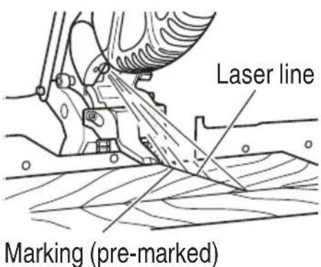
Fig. 13
8. Digital display panel (for C12LCH) (Fig. 14 and Fig. 15)
(1) Turning on the digital display switch shows 0^ for both miter and bevel angle, regardless of main unit angle.
(2) Align the main unit angle with the tilt angle (0°) and miter angle (0°) and hold down their reset buttons for at least 0.2 seconds.
(3) Turning on the laser marker switch while the digital display switch is on, lights up the laser marker (On the C12FCH, only the laser marker switch).
CAUTION
○ When operating the digital panel, have the motor head section at the top limit position and the blade stopped.
If the figure shown on the miter angle digital display is different from the positive stop angle (for example, 45.0^ 45.5^ , 31.6^ 32.0^ )
then the positive stop has probably deviated slightly from its correct position. If this happens, do as follows.
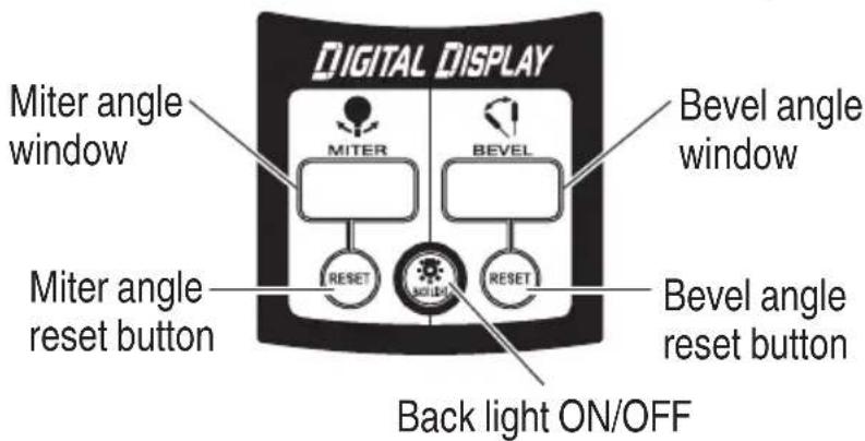
Fig. 14
Switch
(For laser marker)
Switch
(For Digital display)
(Only C12LCH)

natural_image
Technical line drawing of a mechanical component with no visible text or symbolsFig. 15
(1) Move the turntable left and right with the side handle loosened, and set the turntable to the correct position.
(2) If the figures on the display and positive stop still do not match, then return the turntable to the 0^ position. Next move the turntable left and right with the side handle loosened as shown in Fig. 16. After setting it to the correct position 0^ , press the reset button again.
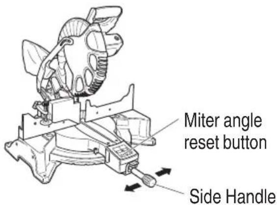
Fig. 16
NOTE
Before starting to cut, align the main unit to the miter angle 0^ and the bevel angle 0^ and hold down the reset buttons for at least
0.2 seconds. If you press the digital display switch to ON without aligning the main unit to 0^ , then the figures appearing on the digital display and the main unit angle will not match.
☐ The laser marker will not light up if the digital display switch is turned off (only on C12LCH).
English
☐ Do not use the main unit near equipment that generates electrical noise such as generators. Electrical noise might cause faulty readings or operation on the digital display.
9. Cutting operation
(1) As shown in Fig. 17 the width of the saw blade is the width of the cut. Therefore, slide the workpiece to the right (viewed from the operator's position) when length ⓑ is desired, or to the left when length ⓐ is desired.
If a laser marker is used, align the laser line with the left side of the saw blade, and then align the ink line with the laser line.
(2) Once the saw blade reaches maximum speed, slowly push down the handle and bring the saw blade in the vicinity of the material to be cut.
(3) Once the saw blade contacts the workpiece, push the handle down gradually to cut into the workpiece.
(4) After cutting the workpiece to the desired depth, turn the power tool OFF and let the saw blade stop completely before raising the handle from the workpiece to return it to the full retract position.
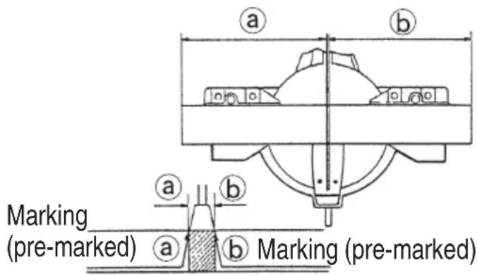
Fig. 17
CAUTION
☐ For maximum dimensions for cutting, refer to “SPECIFICATIONS” table.
○ Increased pressure on the handle will not increase the cutting speed. On the contrary, too much pressure may result in overload of the motor and/or decreased cutting efficiency.
☐ Confirm that the trigger switch is turned OFF and the power plug has been removed from the receptacle whenever the tool is not in use.
Always turn the power off and let the saw blade stop completely before raising the handle from the workpiece. If the handle is raised while the saw blade is still rotating, the cut-off piece may become jammed against the saw blade causing fragments to scatter about dangerously.
Every time one cutting of deep-cutting operation is finished, turn the switch off, and check that the saw blade has stopped. Then raise the handle, and return it to the full retract position.
○ Be absolutely sure to remove the cut material from the top of the turntable, and then proceed to the next step.
- Miter cutting procedures
(1) Loosen the side handle and push the lever for angle stoppers. Then, adjust the turntable until the indicator aligns with desired setting on the miter scale (Fig. 18).
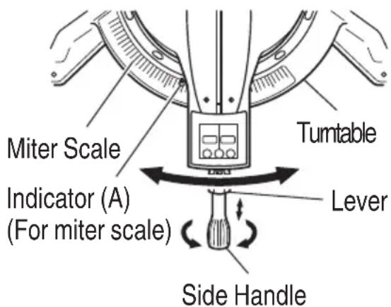
Fig. 18
(2) Re-tighten the side handle to secure the turntable in the desired position.
NOTE
Positive stops are provided at the right and left of the 0^ center setting, at 15^ , 22.5^ , 31.6^ and 45^ settings.
Check that the miter scale and the tip of the indicator are properly aligned.
Operation of the saw with the miter scale and indicator out of alignment, or with the side handle not properly tightened, will result in poor cutting precision.
CAUTION
Never remove the side handle; use of the tool without it would be hazardous. To prevent an accident or personal injury always firmly tighten the miter handle.
- Bevel cutting procedures (Fig. 19)
(1) Loosen the clamp lever and bevel the saw blade to the left.
(2) Adjust the bevel angle to the desired setting while watching the bevel angle scale and indicator, then secure the clamp lever.
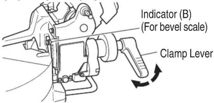
Fig. 19
WARNING
When the workpiece is secured on the left or right side of the blade, the short cut-off portion will come to rest on the right or left side of the saw blade. Always turn the power off and let the saw blade stop completely before raising the handle from the workpiece.
If the handle is raised while the saw blade is still rotating, the cut-off piece may become jammed against the saw blade causing fragments to scatter about dangerously.
When stopping the bevel cutting operation halfway, start cutting after pulling back the motor head to the initial position.
Starting from halfway, without pulling back, causes the lower guard to be caught in the cutting groove of the workpiece and to contact the saw blade.
- Bevel angle fine adjustment (Fig. 20 and Fig. 21)
(1) Grip the handle on the motor head and position it at the bevel angle you need. Temporarily tighten the clamp lever.
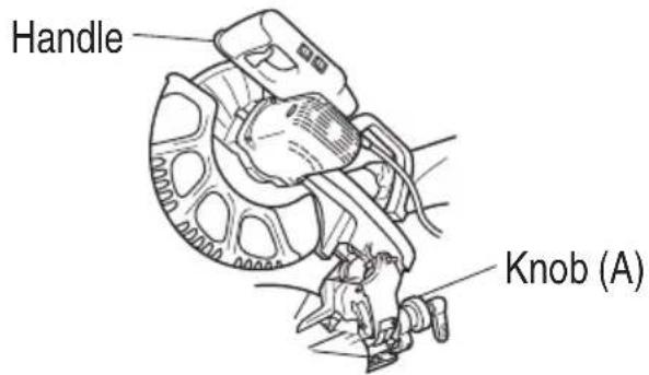
Fig. 20
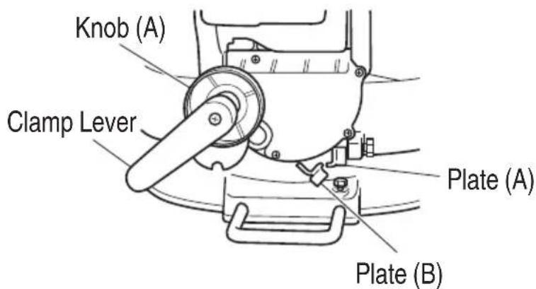
Fig. 21
English
CAUTION
If not tightened firmly enough the motor head might suddenly move or slip, causing injuries. Be sure to tighten the motor head section enough so it will not move.
(2) Make fine adjustments to the bevel angle by gripping the handle and moving the knob (A).
NOTE
Turning knob (A) clockwise, allows fine adjustment of the main unit to the left (as seen from front).
Turning knob (A) counterclockwise, allows fine adjustment of the main unit to the right (as seen from front).
If you tilt the main unit in the direction that does not place a load on plate (A) and pull plate (A), the contact position changes and the right slope angle becomes 3^ .
If you tilt the main unit in the direction that does not place a load on plate (B) and pull plate (B), the contact position changes and the right slope angle becomes 48^ .
(3) After adjusting to the desired angle, tighten the clamp lever and clamp the motor head.
CAUTION
Always check that the clamp lever is secured and the motor head is clamped. If you attempt angle cutting without clamping the motor head, then the motor head might shift unexpectedly causing injuries.
- Compound cutting procedures
Compound cutting can be performed by following the instructions in 10 and 11 above. For maximum dimensions for compound cutting, refer to "SPECIFICATIONS" table.
CAUTION
Always secure the workpiece with the right hand side for compound cutting. Never rotate the table to the right for compound cutting, because the saw blade might then contact the clamp or vise that secures the workpiece, and cause personal injury or damage.
- Installing the holders (Optional accessory)
The holders help keep longer workpieces stable and in place during the cutting operation.
(1) As indicated in Fig. 22, use a steel square for aligning the upper edge of the holders with the base surface.
Loosen the 6 mm wing nut. Turn a height adjustment bolt 6 mm, and adjust the height of the holder.
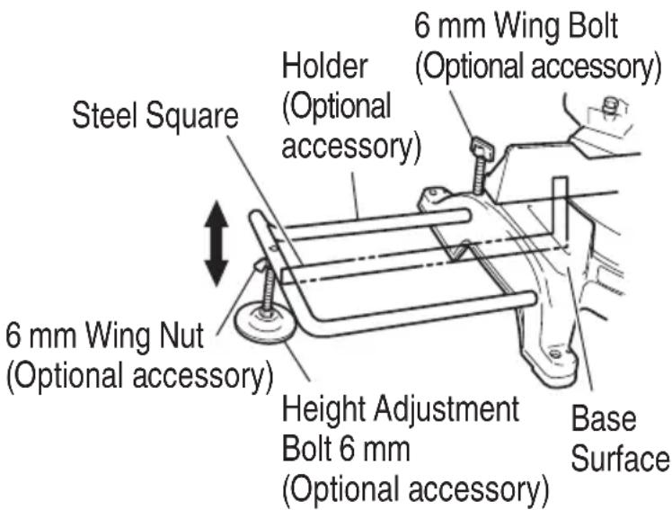
Fig. 22
(2) After adjustment, firmly tighten the wing nut and fasten the holder with the 6 mm knob bolt (optional accessory). If the length of Height Adjustment Bolt 6 mm is insufficient, spread a thin plate beneath. Make sure the end of Height Adjustment Bolt 6 mm does not protrude from the holder.
- Stopper for precision cutting (Stopper and holder are optional accessory)
The stopper facilitates continuous precision cutting in lengths of 280 mm to 450 mm.
To install the stopper, attach it to the holder with the 6 mm wing bolt as shown in Fig. 23.
- Confirmation for use Crown molding vise, Crown molding Stopper (L) and (R) (Optional accessory)
(1) Crown molding Stopper (L) and (R) (optional accessories) allow easier cuts of crown molding without tilting the saw blade. Install them in the base both-sides side to be shown in Fig. 24. After inserting tighten the 6 ~mm knob bolts to secure the Crown molding Stoppers.
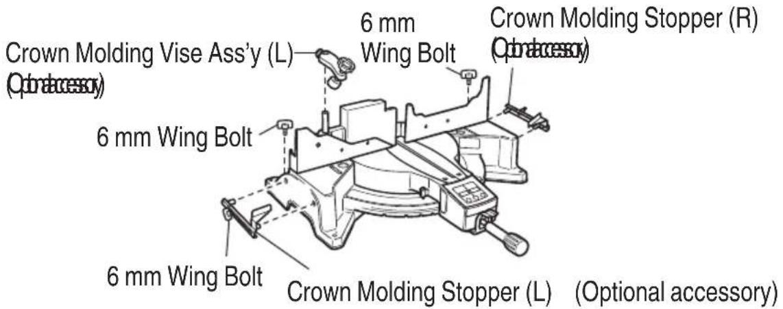
Fig. 24
English
(2) The crown molding vise (B) (Optional accessory) can be mounted on either the left fence (Fence (B)) or the right fence (Fence (A)). It can unite with the slope of the crown molding and vice can be pressed down.
Then turn the upper knob, as necessary, to securely attach the crown molding in position. To raise or lower the vise assembly, first loosen the 6 mm wing bolt.
After adjusting the height, firmly tighten the 6 mm wing bolt; then turn the upper knob, as necessary, to securely attach the crown molding in position (See Fig. 25).
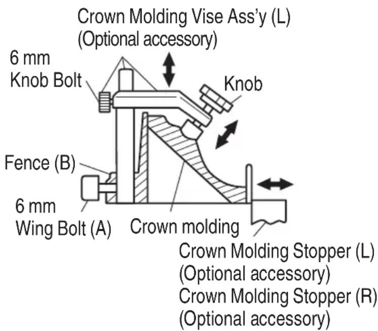
Fig. 25
Position crown molding with its WALL CONTACT EDGE against the guide fence and its CEILING CONTACT EDGE against the Crown molding Stoppers as shown in Fig. 25. Adjust the Crown molding Stoppers according to the size of the crown molding.
Tighten the 6 mm wing bolt to secure the Crown molding Stoppers.
WARNING
Always firmly clamp or vise to secure the crown molding to the fence; otherwise the crown molding might be thrust from the table and cause bodily harm.
Do not bevel cutting. The main body or saw blade may contact the sub fence, resulting in an injury.
CAUTION
Always confirm that the motor head (see Fig. 1 on page 38) does not contact the crown molding vise assembly when it is lowered for cutting. If there is any danger that it may do so, loosen the 6 mm knob bolt and move the crown molding vise assembly to a position where it will not contact the saw blade.
MOUNTING AND DISMOUNTING SAW BLADE
WARNING
To prevent an accident or personal injury, always turn off the trigger switch and disconnect the power plug from the receptacle before removing or installing a blade. If cutting work is done in a state where the bolt is not sufficiently tightened, the bolt can get loose, the blade can come off, and the lower guard can get damaged, resulting in injuries.
Also, check that the bolts are properly tightened before plugging the power plug into the receptacle.
☐ If the bolts are attached or detached using tools other than the 17 mm box wrench (standard accessory), excessive or improperly tightening occurs, resulting in injury.
- Mounting the saw blade (Fig. 26, Fig. 27 and Fig. 28)
(1) Rotate the lower guard (plastic) to the top position.
(2) Press in spindle lock and loosen bolt with 17 mm box wrench (standard accessory).
Since the bolt is left-hand threaded, loosen by turning it to the right as show in Fig. 27.
NOTE
If the spindle lock cannot be easily pressed in to lock the spindle, turn the bolt with 17 mm box wrench (standard accessory) while applying pressure on the spindle lock.
The saw blade spindle is locked when the spindle lock is pressed inward.
(4) Remove the bolt and washer (B).
(5) Lift the lower guard and mount the saw blade.
WARNING
When mounting the saw blade, confi rm that the rotation indicator mark on the saw blade and the rotation direction of the gear case (see Fig. 1 on page 38) are properly matched.
(6) Thoroughly clean washer (B) and the bolt, and install them onto the saw blade spindle.
(7) Press in the spindle lock and tighten the bolt by turning it to the left by standard accessories wrench (17 mm box wrench) as indicated in Fig. 27.
Spindle Lock

natural_image
Line drawing of a mechanical device with no visible text or symbolsFig. 26
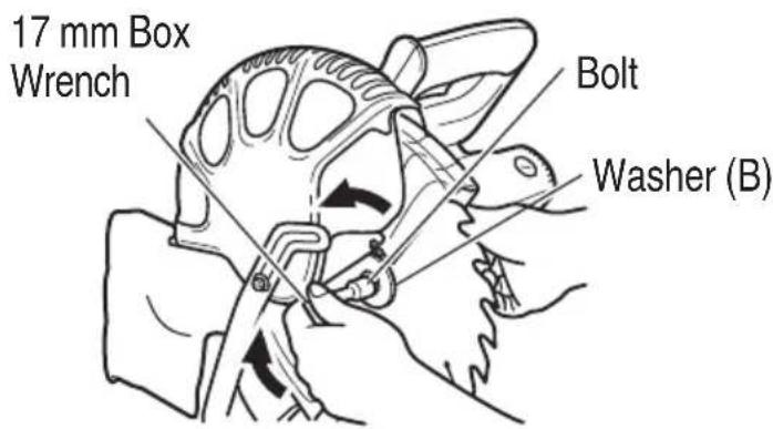
Fig. 27
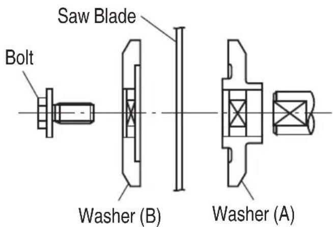
Fig. 28
CAUTION
○ Confirm that the spindle lock has returned to the retract position after installing or removing the saw blade.
○ Tighten the bolt so it does not come loose during operation.
○ Confirm that the bolt has been properly tightened before the power tool is started.
2. Dismounting the saw blade
Dismount the saw blade by reversing the mounting procedures described in paragraph 1 above. The saw blade can easily be removed after lifting the lower guard.
MAINTENANCE AND INSPECTION
WARNING
To avoid an accident or personal injury, always confirm the trigger switch is turned OFF and that the power plug has been disconnected from the receptacle before performing any maintenance or inspection of this tool.
- Inspecting the saw blade
Always replace the saw blade immediately upon the first sign of deterioration or damage. A damaged saw blade can cause personal injury and a worn saw blade can cause ineffic active operation and possible overload to the motor.
CAUTION
Never use a dull saw blade. When a saw blade is dull, its resistance to the hand pressure applied by the tool handle tends to increase, making it unsafe to operate the power tool.
- Inspecting the lever (Fig. 29 and Fig. 30)
If the M8 hexagonal head bolts (2) are loose, align the sides of the fence and saw blade with the steel square. After adjusting the saw blade and fence to a ninety-degree angle, tighten the lever securing hexagonal head bolts (2).
- Inspecting the carbon brushes (Fig. 31 and Fig. 32)
The carbon brushes in the motor are expendable parts.
If the carbon brushes become excessively worn, motor trouble might occur.
Therefore, inspect the carbon brushes periodically and replace them when they have become worn to the wear limit line as shown in Fig. 31.
Also, keep the carbon brushes clean so that they will slide smoothly within the brush holders.
The carbon brushes can easily be removed after removal of the brush caps (see Fig. 32) with a slotted (minus) screwdriver.
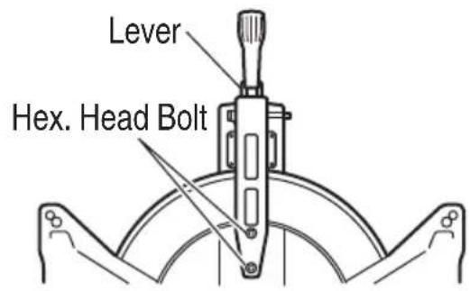
Fig. 29
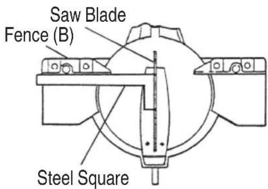
Fig. 30
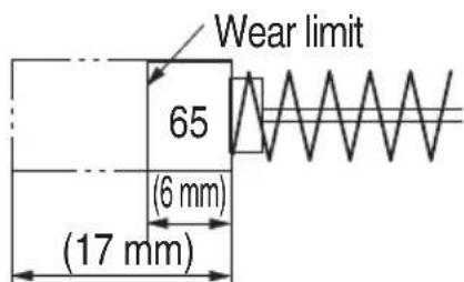
Fig. 31

Fig. 32
4. About Handling the Motor (see Fig. 1 on page 38)
Winding of the motor is said to be the heart of this tool. Exercise utmost caution not to damage the winding by exposing it to wash oil or water.
NOTE
Accumulation of dust and the like inside the motor can result in a malfunction.
After using the motor for 50 hours or so, carry out no-load running, and blow in the dry air from a wind hole at the motor's rear. Such action is effective to discharge dust and the like.
5. Inspecting the screws
Regularly inspect each component of the power tool for looseness.
Re-tighten screws on any loose part.
WARNING
To prevent personal injury, never operate the power tool if any components are loose.
6. Inspecting the lower guard for proper operation
Before each use of the tool, test the lower guard (see Fig. 1 on page 38) to assure that it is in good condition and that it moves smoothly.
Never use the tool unless the lower guard operates properly and it is in good mechanical condition.
7. Storage
After operation of the tool has been completed, check that the following has been performed:
(1) Trigger switch is in OFF position,
(2) Power plug has been removed from the receptacle,
When the tool is not in use, keep it stored in a dry place out of the reach of children.
8. Lubrication
Lubricate the following sliding surfaces once a month to keep the power tool in good operating condition for a long time (Fig. 1 on page 38 and Fig. 2 on page 38).
Use of machine oil is recommended.
Oil supply points:
* Rotary portion of hinge
* Rotary portion of vise assembly
9. Cleaning
Periodically remove chips, dust and other waste material from the surface of the power tool, especially from the inside of the lower guard with a damp, soapy cloth. To avoid a malfunction of the motor, protect it from contact with oil or water.
If the laser line becomes invisible due to chips and the like adhered onto the window of the laser marker's light-emitting section, wipe and clean the window with a dry cloth or a soft cloth moistened with soapy water, etc.
English
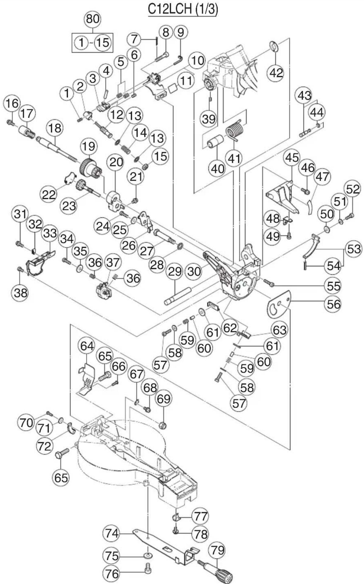
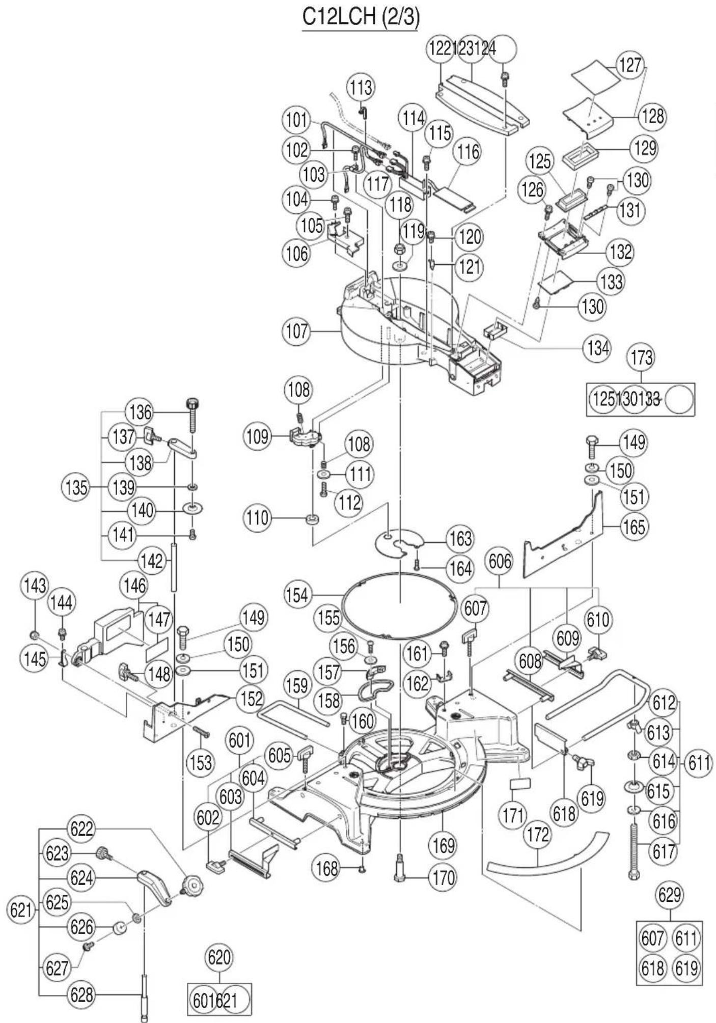
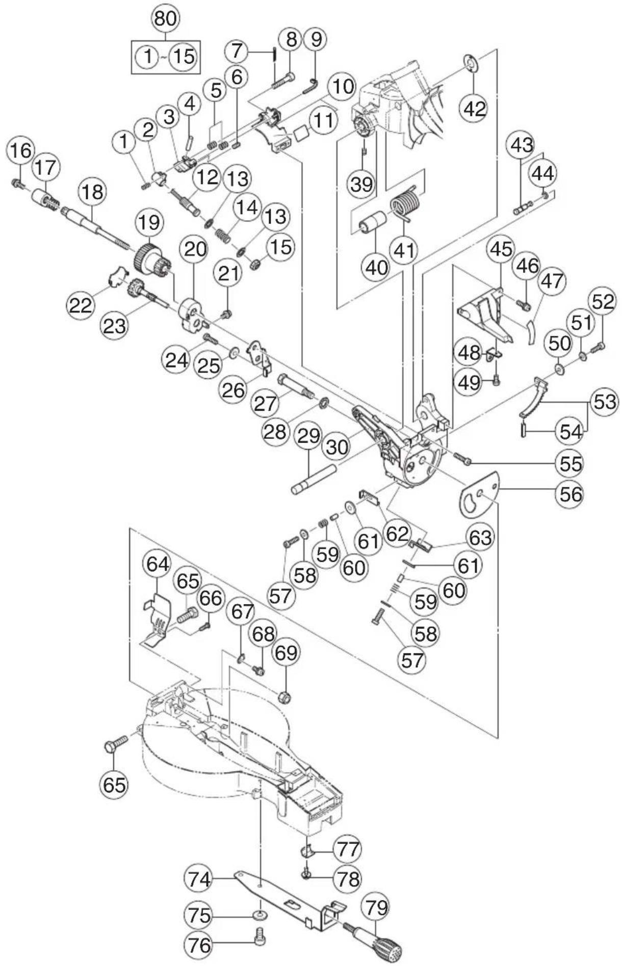
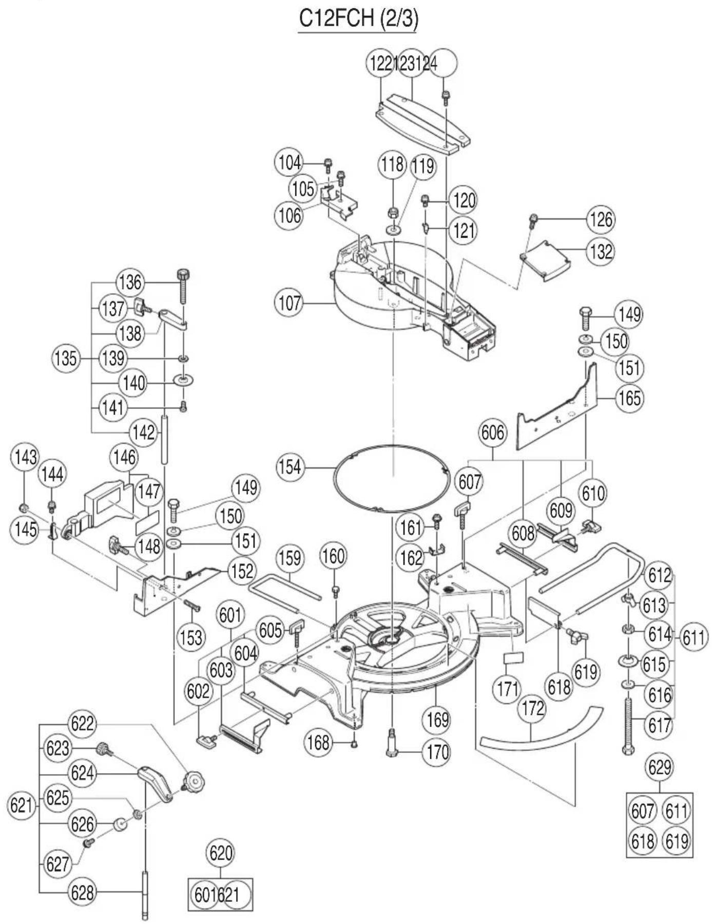
10. Service parts list
CAUTION
Repair, modification and inspection of HiKOKI Power Tools must be carried out by a HiKOKI Authorized Service Center.
Especially laser device should be maintained by the authorised agent by laser manufacturer.
Always assign the repair of laser device to HiKOKI Authorised Service Center.
This Parts List will be helpful if presented with the tool to the HiKOKI Authorized Service Center when requesting repair or other maintenance.
In the operation and maintenance of power tools, the safety regulations and standards prescribed in each country must be observed.
SERVICE PARTS LIST
English
| Item No. | Code No. | No. Used | Remarks |
| 1 | 323-141 | 1 | |
| 2 | 323-137 | 1 | |
| 3 | 323-138 | 1 | |
| 4 | 949-900 | 1 D3 × 14 | |
| 5 | 323-142 | 2 | |
| 6 | 962-782 | 1 M5 × 6 | |
| 7 | 949-531 | 1 D2 × 12 | |
| 8 | 323-144 | 1 M5 | |
| 9 | 975-144 | 1 | |
| 10 | 323-139 | 1 “11” | |
| 11 | 1 | ||
| 12 | 323-647 | 1 | |
| 13 | 323-143 | 2 | |
| 14 | 323-140 | 1 | |
| 15 | 323-136 | 1 | |
| 16 | 323-208 | 1 M6 × 20 | |
| 17 | 322-935 | 1 | |
| 18 | 323-665 | 1 M10 | |
| 19 | 323-666 | 1 | |
| 20 | 323-597 | 1 | |
| 21 | 304-043 | 1 M4 × 10 | |
| 22 | 323-598 | 1 | |
| 23 | 323-599 | 1 | |
| 24 | 949-821 | 1 M5 × 16 | |
| 25 | 949-454 | 1 | |
| 26 | 323-596 | 1 | |
| 27 | 322-933 | 1 | |
| 28 | 322-934 | 1 M16 | |
| 29 | 323-593 | 1 | |
| 30 | 323-663 | 1 | |
| 31 | 993-539 | 1 M4 × 16 | |
| 32 | 980-523 | 1 | |
| 33 | 323-600 | 1 | |
| 34 | 949-241 | 1 M5 × 20 | |
| 35 | 949-432 | 1 M6 | |
| 36 | 323-142 | 2 | |
| 37 | 323-619 | 1 | |
| 38 | 949-216 | 4 M4 × 10 | |
| 39 | 307-956 | 1 M6 × 10 | |
| 40 | 323-594 | 1 |
| Item No. | Code No. | No. Used | Remarks |
| 41 | 323-595 | 1 | |
| 42 | 323-684 | 1 | |
| 43 | 302-518 | 1 “44” | |
| 44 | 984-528 | 1 P-6 | |
| 45 | 323-601 | 1 “47-49” | |
| 46 | 990-541 | 2 M5 × 16 | |
| 47 | 323-602 | 1 | |
| 48 | 322-963 | 1 | |
| 49 | 949-214 | 1 M4 × 6 | |
| 50 | 949-431 | 1 M5 | |
| 51 | 949-454 | 1 M5 | |
| 52 | 949-821 | 1 M5 × 16 | |
| 53 | 323-664 | 1 “54” | |
| 54 | 949-900 | 1 D3 × 14 | |
| 55 | 949-660 | 2 M6 × 20 | |
| 56 | 323-683 | 1 | |
| 57 | 949-221 | 2 M4 × 20 | |
| 58 | 949-423 | 2 M4 | |
| 59 | 323-142 | 2 | |
| 60 | 303-006 | 2 D4 × 10 | |
| 61 | 949-432 | 2 M6 | |
| 62 | 323-662 | 1 | |
| 63 | 323-661 | 1 | |
| 64 | 323-659 | 1 | |
| 65 | 303-409 | 2 M8 × 25 | |
| 66 | 935-196 | 2 M4 × 12 | |
| 67 | 322-893 | 1 | |
| 68 | 304-043 | 1 M4 × 10 | |
| 69 | 680-418 | 1 M12 | |
| 70 | 949-217 | 2 M4 × 12 | |
| 71 | 949-423 | 2 M4 | |
| 72 | 323-607 | 1 | |
| 74 | 323-627 | 1 | |
| 75 | 949-457 | 2 M8 | |
| 76 | 949-655 | 2 M8 × 16 | |
| 77 | 323-609 | 1 | |
| 78 | 307-635 | 2 M4 × 10 | |
| 79 | 323-680 | 1 | |
| 80 | 323-646 | 1 “1-10,12-15” |
English
| Item No. | Code No. | No. Used | Remarks | Item No. | Code No. | No. Used | Remarks |
| 101 | 323-658 | 1 380MM | 141 | 949-216 | 1 M4 × 10 | ||
| 102 | 993-539 | 1 M4 × 16 | 142 | 322-954 | 1 | ||
| 103 | 973-313 | 1 | 143 | 311-144 | 1 M6 | ||
| 104 | 304-043 | 1 M4 × 10 | 144 | 304-043 | 1 M4 × 10 | ||
| 105 | 993-539 | 1 M4 × 16 | 145 | 323-631 | 1 | ||
| 106 | 323-650 | 1 | 146 | 323-630 | 1 “147” | ||
| 107 | 323-624 | 1 | 147——— | 1 | |||
| 108 | 323-142 | 2 | 148 | 301-806 | 1 M6 × 15 | ||
| 109 | 323-619 | 1 | 149 | 949-678 | 4 M8 × 35 | ||
| 110 | 323-622 | 1 | 150 | 949-457 | 4 M8 | ||
| 111 | 949-432 | 1 M6 | 151 | 949-433 | 4 M8 | ||
| 112 | 949-241 | 1 M5 × 20 | 152 | 323-629 | 1 | ||
| 113 | 975-144 | 1 | 153 | 323-685 | 1 M6 × 30 | ||
| 114 | 323-621 | 1 | 154 | 323-625 | 3 | ||
| 115 | 993-539 | 1 M4 × 16 | 155 | 302-317 | 2 M5 × 16 | ||
| 116 | 323-617 | 1 | 156 | 949-431 | 2 M5 | ||
| 117 | 323-620 | 1 160MM | 157 | 323-604 | 1 | ||
| 118 | 975-348 | 1 M8 | 158 | 323-603 | 1 | ||
| 119 | 318-929 | 1 | 159 | 322-910 | 1 | ||
| 120 | 304-043 | 1 M4 × 10 | 160 | 949-610 | 1 M6 × 10 | ||
| 121 | 318-927 | 1 | 161 | 987-512 | 1 M5 × 16 | ||
| 122 | 323-648 | 1 | 162 | 323-605 | 1 | ||
| 123 | 323-649 | 1 | 163 | 323-623 | 1 | ||
| 124 | 990-541 | 4 M5 × 16 | 164 | 949-215 | 1 M4X × 8 | ||
| 125 | 323-612 | 1 | 165 | 323-628 | 1 | ||
| 126 | 993-539 | 4 M4 × 16 | 168 | 323-606 | 4 | ||
| 127 | 323-616 | 1 | 169———“168,171,172” | ||||
| 128 | 323-615 | 1 “127” | 170 | 323-626 | 1 | ||
| 129 | 323-608 | 1 | 171——— | 1 | |||
| 130 | 321-672 | 10 D2 × 6 | 172 | 323-656 | 1 | ||
| 131 | 323-613 | 1 | 173 | 323-610 | 1 “125,130-133” | ||
| 132 | 323-611 | 1 | 601 | 323-546 | 1 “602-605” | ||
| 133 | 323-614 | 1 | 602 | 301-806 | 1 M6 × 15 | ||
| 134 | 323-618 | 1 | 603——— | 1 | |||
| 135 | 323-677 | 1 “136-142” | 604 | 321-390 | 1 | ||
| 136 | 323-678 | 1 | 605 | 323-682 | 1 M6 × 85 | ||
| 137 | 301-806 | 1 M6 × 15 | 606 | 323-547 | 1 “607-610” | ||
| 138——— | 1 | 607 | 323-682 | 2 M6 × 85 | |||
| 139 | 949-432 | 1 M6 | 608 | 321-390 | 1 | ||
| 140 | 302-532 | 1 | 609——— | 1 | |||
| Item No. | Code No. | No. Used | Remarks |
610 301-806 1 M6 × 15
611 323-657 1 "612-617"
612 321-549 1
613 949-313 1 M6
614 949-556 1 M6
615 322-047 1
616 949-425 1 M6
617 323-681 1 M6 × 105
618 974-561 1
619 949-404 1 M6X × 20
620 323-545 1 "601,621"
621 322-957 1 "622-628"
622 321-551 1 M10 × 54
623 998-836 1 M6 × 11
624—1
625 306-985 1
626 964-851 1
627 304-043 1 M4 × 10
628 318-967 1
629 323-523 1 "607,611,618,619"
English
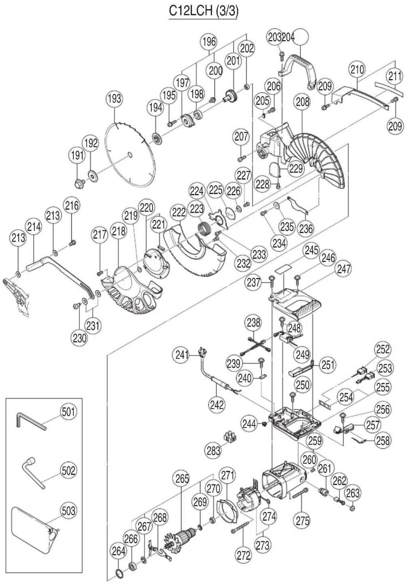
| Item No. | Code No. | No. Used | Remarks |
| 191 | 988-101 | 1 M10 | |
| 192 | 323-652 | 1 | |
| 193 | 305MM-D25.4-NT120 | ||
| 194 | 323-651 | 1 | |
| 195 | 323-208 | 2 M6 × 20 | |
| 196 | 323-639 | 1 “197,198,200-202” | |
| 197 | 323-641 | 1 | |
| 198 | 320-3VV | 1 6203VVCMPS2L | |
| 200 | 304-043 | 2 M4 × 10 | |
| 201 | 323-640 | 1 | |
| 202 | 608-VVM | 1 608VVC2PS2L | |
| 203 | 323-208 | 2 M6 × 20 | |
| 204 | 322-924 | 1 | |
| 205 | 980-523 | 1 | |
| 206 | 935-196 | 1 M4 × 12 | |
| 207 | 949-755 | 1 M6 × 16 | |
| 208 | 323-638 | 1 | |
| 209 | 993-539 | 2 M4 × 16 | |
| 210 | 323-653 | 1 “211” | |
| 211 | 323-654 | 1 | |
| 213 | 322-948 | 2 M7 | |
| 214 | 323-674 | 1 | |
| 216 | 322-950 | 1 M6 | |
| 217 | 318-363 | 1 M4 × 10 | |
| 218 | 323-668 | 1 | |
| 219 | 949-454 | 1 M5 | |
| 220 | 323-672 | 1 “221” | |
| 221 | 323-673 | 1 | |
| 222 | 323-667 | 1 | |
| 223 | 323-671 | 1 | |
| 224 | 323-669 | 1 | |
| 225 | 323-670 | 1 | |
| 226 | 949-454 | 1 M5 | |
| 227 | 949-236 | 1 M5 × 10 | |
| 228 | 949-216 | 1 M4 × 10 | |
| 229 | 322-926 | 1 | |
| 230 | 322-947 | 1 M5 | |
| 231 | 322-938 | 2 M10 | |
| 232 | 949-215 | 3 M4 × 8 | |
| 233 | 323-040 | 3 M5 × 10 | |
| 234 | 323-040 | 2 M5 × 10 | |
| 235 | 949-431 | 1 M5 | |
| 236 | 323-675 | 1 |
| Item No. | Code No. | No. Used | Remarks |
| 237 | 307-028 | 2 D4 × 25 | |
| 238 | 323-632 | 1 | |
| 239 | 984-750 | 2 D4 × 16 | |
| 240 | 937-631 | 1 | |
| 241 | 1 | ||
| 242 | 940-778 | 1 D10.7 | |
| 244 | 319-349 | 1 | |
| 245 | 1 | ||
| 246 | 301-653 | 4 D4 × 20 | |
| 247 | 323-642 | 1 | |
| 248 | 984-750 | 1 D4 × 16 | |
| 249 | 322-911 | 1 | |
| 250 | 301-653 | 2 D4 × 20 | |
| 251 | 323-645 | 1 | |
| 252 | 323-634 | 1 | |
| 253 | 323-635 | 1 | |
| 254 | 323-644 | 1 | |
| 255 | 323-643 | 1 “254” | |
| 256 | 984-750 | 1 D4 × 16 | |
| 257 | 320-950 | 1 | |
| 258 | 323-633 | 1 | |
| 259 | 322-914 | 1 “260,261” | |
| 260 | 938-477 | 2 M5 × 8 | |
| 261 | 938-241 | 2 | |
| 262 | 999-065 | 2 | |
| 263 | 945-161 | 2 | |
| 264 | 303-792 | 1 | |
| 265 | 1 “266,267,269,270” | ||
| 266 | 620-2VV | 1 6202VVCMPS2L | |
| 267 | 980-700 | 1 | |
| 268 | 323-637 | 1 | |
| 269 | 302-428 | 1 | |
| 270 | 600-0VV | 1 6000VVCMPS2L | |
| 271 | 322-915 | 1 | |
| 272 | 953-174 | 2 D5 × 55 | |
| 273 | 1 “274” | ||
| 274 | 937-623 | 2 | |
| 275 | 322-123 | 4 M5 × 40 | |
| 283 | 958-308Z | 1 | |
| 501 | 944-458 | 1 4MM | |
| 502 | 985-051 | 1 17MM | |
| 503 | 322-955 | 1 |
C12FCH (1/3)
| Item No. | Code No. | No. Used | Remarks |
| 1 | 323-141 1 | ||
| 2 | 323-137 1 | ||
| 3 | 323-138 1 | ||
| 4 | 949-900 1 | D3 × 14 | |
| 5 | 323-142 2 | ||
| 6 | 962-782 1 | M5 × 6 | |
| 7 | 949-531 1 | D2 × 12 | |
| 8 | 323-144 1 | M5 | |
| 9 | 975-144 1 | ||
| 10 | 323-139 1 | "11" | |
| 11 | 1 | ||
| 12 | 323-647 1 | ||
| 13 | 323-143 2 | ||
| 14 | 323-140 1 | ||
| 15 | 323-136 1 | ||
| 16 | 323-208 1 | M6 × 20 | |
| 17 | 322-935 1 | ||
| 18 | 323-665 1 | M10 | |
| 19 | 323-666 1 | ||
| 20 | 323-597 1 | ||
| 21 | 304-043 1 | M4 × 10 | |
| 22 | 323-598 1 | ||
| 23 | 323-599 1 | ||
| 24 | 949-821 1 | M5 × 16 | |
| 25 | 949-454 1 | ||
| 26 | 323-596 1 | ||
| 27 | 322-933 1 | ||
| 28 | 322-934 1 | M16 | |
| 29 | 323-593 1 | ||
| 30 | 323-663 1 | ||
| 39 | 307-956 1 | M6 × 10 | |
| 40 | 323-594 1 | ||
| 41 | 323-595 1 | ||
| 42 | 323-684 1 | ||
| 43 | 302-518 1 | "44" | |
| 44 | 984-528 1 | P-6 | |
| 45 | 323-719 1 | "47-49" | |
| 46 | 990-541 2 | M5 × 16 | |
| 47 | 323-697 1 | ||
| 48 | 322-963 1 |
| Item No. | Code No. | No. Used | Remarks |
| 49 | 949-214 | 1 M4 × 6 | |
| 50 | 949-431 | 1 M5 | |
| 51 | 949-454 | 1 M5 | |
| 52 | 949-821 | 1 M5 × 16 | |
| 53 | 323-664 | 1 “54” | |
| 54 | 949-900 | 1 D3 × 14 | |
| 55 | 949-660 | 2 M6 × 20 | |
| 56 | 323-683 | 1 | |
| 57 | 949-221 | 2 M4 × 20 | |
| 58 | 949-423 | 2 M4 | |
| 59 | 323-142 | 2 | |
| 60 | 303-006 | 2 D4 × 10 | |
| 61 | 949-432 | 2 M6 | |
| 62 | 323-662 | 1 | |
| 63 | 323-661 | 1 | |
| 64 | 323-659 | 1 | |
| 65 | 303-409 | 2 M8 × 25 | |
| 66 | 935-196 | 2 M4 × 12 | |
| 67 | 322-893 | 1 | |
| 68 | 304-043 | 1 M4 × 10 | |
| 69 | 680-418 | 1 M12 | |
| 74 | 323-627 | 1 | |
| 75 | 949-457 | 2 M8 | |
| 76 | 949-655 | 2 M8 × 16 | |
| 77 | 323-609 | 1 | |
| 78 | 307-635 | 2 M4 × 10 | |
| 79 | 323-680 | 1 | |
| 80 | 323-646 | 1 “1-10,12-15” |
English
| Item No. | Code No. | No. Used | Remarks |
| 104 | 949-216 | 1 M4 × 10 | |
| 105 | 954-878 | 1 M4 × 16 | |
| 106 | 323-650 | 1 | |
| 107 | 323-624 | 1 | |
| 118 | 975-348 | 1 M8 | |
| 119 | 318-929 | 1 | |
| 120 | 304-043 | 1 M4 × 10 | |
| 121 | 318-927 | 1 | |
| 122 | 323-648 | 1 | |
| 123 | 323-649 | 1 | |
| 124 | 990-541 | 4 M5 × 16 | |
| 126 | 993-539 | 4 M4 × 16 | |
| 132 | 323-693 | 1 | |
| 135 | 323-677 | 1 “136-142” | |
| 136 | 323-678 | 1 | |
| 137 | 301-806 | 1 M6 × 15 | |
| 138 | 1 | ||
| 139 | 949-432 | 1 M6 | |
| 140 | 302-532 | 1 | |
| 141 | 949-216 | 1 M4 × 10 | |
| 142 | 322-954 | 1 | |
| 143 | 311-144 | 1 M6 | |
| 144 | 304-043 | 1 M4 × 10 | |
| 145 | 323-631 | 1 | |
| 146 | 323-630 | 1 “147” | |
| 147 | 1 | ||
| 148 | 301-806 | 1 M6 × 15 | |
| 149 | 949-678 | 4 M8 × 35 | |
| 150 | 949-457 | 4 M8 | |
| 151 | 949-433 | 4 M8 | |
| 152 | 323-629 | 1 | |
| 153 | 323-685 | 1 M6 × 30 | |
| 154 | 323-625 | 3 | |
| 159 | 322-910 | 1 | |
| 160 | 949-610 | 1 M6 × 10 | |
| 161 | 987-512 | 1 M5 × 16 | |
| 162 | 323-605 | 1 | |
| 165 | 323-628 | 1 | |
| 168 | 323-606 | 4 | |
| 169 | 1 “168,171,172” |
| Item No. | Code No. | No. Used | Remarks |
| 170 | 323-626 | 1 | |
| 171 | 1 | ||
| 172 | 323-692 | 1 | |
| 601 | 323-546 | 1 “602-605” | |
| 602 | 301-806 | 1 M6 × 15 | |
| 603 | 1 | ||
| 604 | 321-390 | 1 | |
| 605 | 323-682 | 1 M6 × 85 | |
| 606 | 323-547 | 1 “607-610” | |
| 607 | 323-682 | 2 M6 × 85 | |
| 608 | 321-390 | 1 | |
| 609 | 1 | ||
| 610 | 301-806 | 1 M6 × 15 | |
| 611 | 323-657 | 1 “612-617” | |
| 612 | 321-549 | 1 | |
| 613 | 949-313 | 1 M6 | |
| 614 | 949-556 | 1 M6 | |
| 615 | 322-047 | 1 | |
| 616 | 949-425 | 1 M6 | |
| 617 | 323-681 | 1 M6 × 105 | |
| 618 | 974-561 | 1 | |
| 619 | 949-404 | 1 M6X × 20 | |
| 620 | 323-545 | 1 “601,621” | |
| 621 | 322-957 | 1 “622-628” | |
| 622 | 321-551 | 1 M10 × 54 | |
| 623 | 998-836 | 1 M6 × 11 | |
| 624 | 1 | ||
| 625 | 306-985 | 1 | |
| 626 | 964-851 | 1 | |
| 627 | 304-043 | 1 M4 × 10 | |
| 628 | 318-967 | 1 | |
| 629 | 323-523 | 1 “607,611,618,619” |
English
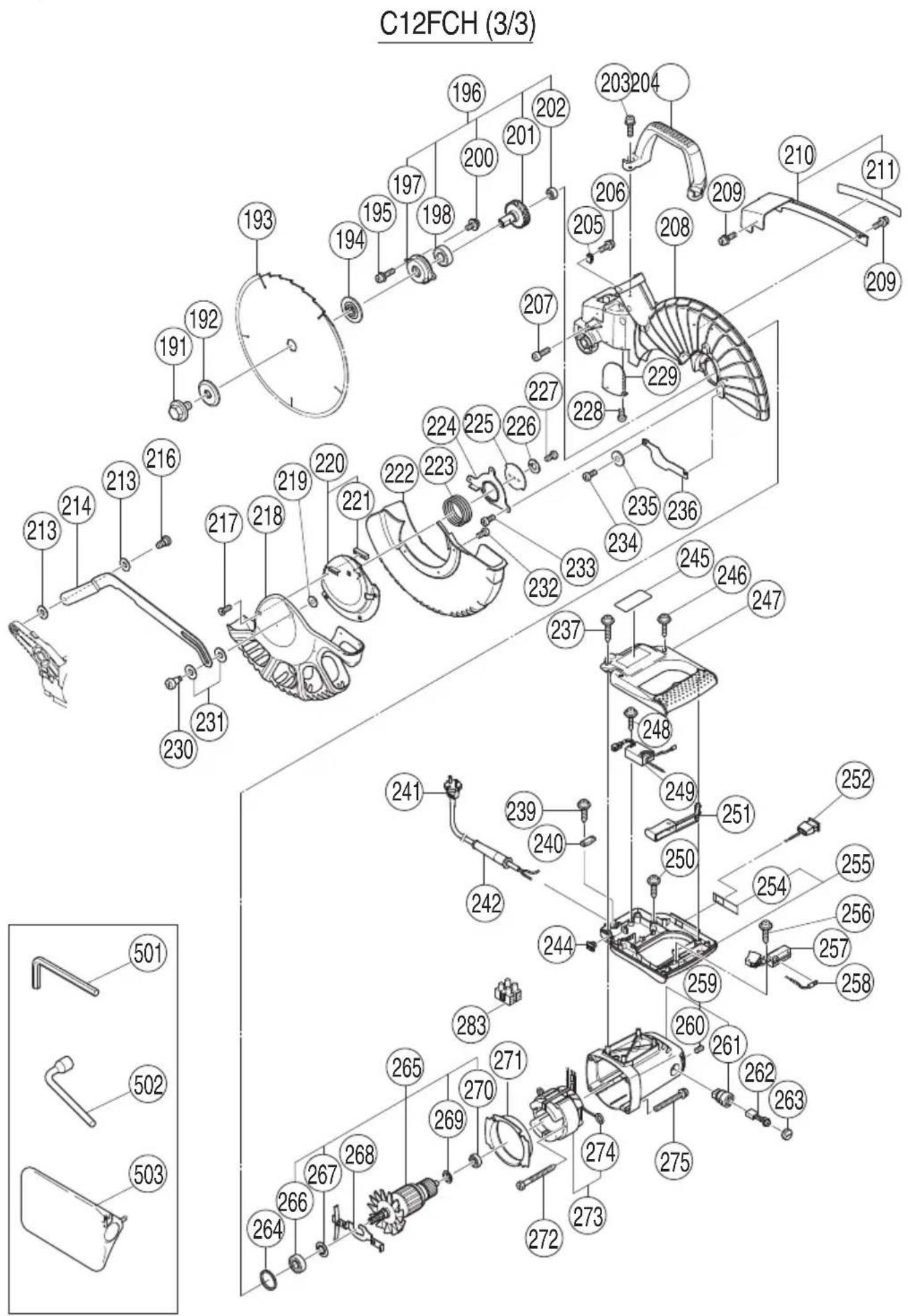
Item No. Code No. No. Remarks Used
191988-1011M10
192323-6521
193 305MM-D25.4-NT120
194323-6511
195 323-208 2 M6 × 20
196323-6391"197,198,200-202"
197323-6411
198620-3VV16203VVCMPS2L
200 304-043 2 M4 × 10
201323-6401
202608-VVM1608VVC2PS2L
203 323-208 2 M6 × 20
204322-9241
205980-5231
Item No. Code No. No. Remarks Used
236323-6751
237 307-028 2 D4 × 25
239 984-750 2 D4 × 16
240937-6311
241 1
242940-7781D10.7
244319-3491
245 1
246 301-653 4 D4 × 20
247323-6421
248 984-750 1 D4 × 16
249322-9111
250 301-653 2 D4 × 20
251323-6451
252323-6341
254323-6951
255323-6941"254"
256 984-750 1 D4 × 16
257320-9501
258323-6331
259322-9141"260,261"
260 938-477 2 M5 × 8
261938-2412
262999-0652
263945-1612
264303-7921
265——1“266,267,269,270”
266620-2VV16202VVC MPS2L
267980-7001
268323-6371
269302-4281
270600-0VV16000VVCMPS2L
271322-9151
272 953-174 2 D5 × 55
273——1“274”
274937-6232
275 322-123 4 M5 × 40
283958-308Z1
501944-45814MM
502985-051117MM
503322-9551
服务中心
工机商业(中国)有限公司