
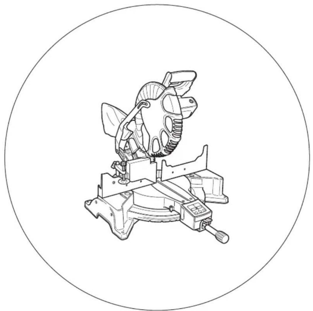
C12LCH - Scie HiKOKI - Notice d'utilisation et mode d'emploi gratuit
Retrouvez gratuitement la notice de l'appareil C12LCH HiKOKI au format PDF.

| Type de produit | Scie à onglet composée |
| Marque | HiKOKI |
| Modèle | C12LCH / C12FCH |
| Dimensions (L x l x H) | 625 mm x 775 mm x 610 mm |
| Poids | 19,5 kg (C12LCH) / 19 kg (C12FCH) |
| Alimentation | 220 V ~ 50/60 Hz |
| Puissance absorbée | 1520 W |
| Vitesse à vide | 4000 tr/min |
| Diamètre de lame | 305 mm (maxi 305 mm, mini 290 mm) |
| Alésage de lame | 25,4 mm |
| Épaisseur de lame | 2,7 mm |
| Capacité de coupe à 0° (H x L) | 63,5 mm x 200 mm ou 98 mm x 155 mm |
| Capacité de coupe à onglet 45° (H x L) | 63,5 mm x 140 mm |
| Capacité de coupe à biseau gauche 45° (H x L) | 42 mm x 200 mm |
| Capacité de coupe composée (biseau 45°, onglet 45°) | 42 mm x 140 mm |
| Plage d'angle d'onglet | 0° – 52° à droite et à gauche |
| Plage d'angle de biseau | -3° – 48° à gauche |
| Affichage numérique | Oui, précis à ±0,5° (modèle C12LCH) |
| Marquage laser | Oui, classe II, 654 nm, < 3 mW |
| Accessoires fournis | Lame TCT 305 mm, sac à poussière, clé à douille 17 mm, étau, clé hexagonale 4 mm |
| Entretien et nettoyage | Lubrification mensuelle des surfaces coulissantes ; nettoyage régulier du carter inférieur ; remplacer les balais de charbon usés ; confier les réparations à un centre agréé HiKOKI |
| Sécurité | Carter inférieur mobile, arrêt du moteur, verrouillage de la gâchette, coupe-circuit |
FOIRE AUX QUESTIONS - C12LCH HiKOKI
Questions des utilisateurs sur C12LCH HiKOKI
0 question sur cet appareil. Repondez a celles que vous connaissez ou posez la votre.
Poser une nouvelle question sur cet appareil
Téléchargez la notice de votre Scie au format PDF gratuitement ! Retrouvez votre notice C12LCH - HiKOKI et reprennez votre appareil électronique en main. Sur cette page sont publiés tous les documents nécessaires à l'utilisation de votre appareil C12LCH de la marque HiKOKI.
MODE D'EMPLOI C12LCH HiKOKI
复合式斜口锯
Compound Miter Saw
C 12LCH · C 12FCH
natural_image
Technical line drawing of a mechanical device with a circular frame (no text or symbols)保留备用
Keep for future reference

使用说明书
Handling instructions

目次
作业上的一般注意事项....2
使用复合锯须知....3
符号....5
部件名称....5
规格....6
标准附件....7
选购件(另售)....7
用途....7
打开包装....7
作业之前....7
使用前调节电动工具....8
实际应用....9
锯条的安装和拆卸....17
维护和检查....19
维修零部件一览表....21
作业上的一般注意事项
警告!
当使用电动工具时,为了减少造成火灾、电击和人身伤害,必须时刻遵守基本注意事项,以及下述操作注意事项。
在操作本机之前,请通读本说明书,并予以妥善保管。
安全操作注意事项:
- 工作场所应打扫干净,清理妥当,杂乱无章将导致事故。
-
确保妥适的作业环境。电动工具不可任其风吹雨打。不得在潮湿的地方作业。工作场所需保持充分的亮度。
请勿在有可能造成火灾或爆炸的地方使用电动工具。 -
谨防触电事故。应避免身体同大地或接地表面接触不可让访客触摸电动工具或延伸线缆(例如:管道、散热器、炉灶、冰箱等)。
-
不可让孩童和体弱人士靠近工作场所。请勿让访客触摸工具或延伸线缆。与作业无关的访客也必须保持安全距离。
-
不使用的电动工具应存放到干燥而孩童和体弱人士伸手不及的高处,并加锁保管。
-
不得使劲用力推压。电动工具需按设计条件才能有效而安全地工作,绝不可勉强。
-
妥选使用工具。不可用小型工具或附件去干重活。不可用于规定外的作业。举例说,用圆锯进行伐木打枝或原木锯切作业。
-
工作时衣服穿戴要合适。不要让松散的衣角和宝石类卷入转动部份。屋外作业时,最好手戴橡胶手套,脚穿防滑胶鞋。同时要戴上能够罩笼长发的工作帽。
-
绝大多数的电动工具作业时,均需戴安全眼镜。进行粉尘飞扬的切削作业时,需戴防尘面罩。
-
连接除尘设备。
如果提供连击除尘和集尘的设备,请确认是否已经连接好并且使用正常。
-
不要拿电线提起电动工具,也不得拉扯电线从电源插座拆除插头。电线需从热源和油液隔开,并避免与锐利的边缘接触。
-
作业以安全第一为原则。工件要用夹具或台钳卡紧。这样做,比用手按压更为可靠,也能够让双手专心操作。
-
作业时脚步要站稳,身体姿势要保持平衡。
-
工具应维护妥善,经常保持锋利、清洁才能充分发挥性能,落实作业安全的要求。应按规定加注润滑脂、更换附件。线缆应定期检查,如发现损伤应即委托专业性的服务单位加以修复。延伸电缆如有损伤应予更换。手柄要保持干燥,并防止沾附油脂类。
-
不使用时、维修前以及更换附件(如:刀具、钻头、锯具等)之前,都必须拆卸电源插头才行。
-
开动前务必把调整用键和扳手类拆除下来。这一点与安全有关。应养成习惯,严格遵守。
-
谨防误开动。插头一插上电源插座,指头就不可随便接触电源开关。插接电源之前,应先确认:开关是否切断。
-
室外延伸线缆的使用。室外作业时,必须使用专用的延伸线缆。
-
保持高度警觉,充分掌握情况,以正常的判断力从事作业。疲惫时切不可开动电动工具。
-
检查损坏部件。在继续使用电动工具之前,应详细检查各部零件以及防护装置有无损坏,以便判断工具能否正常工作、能否发挥正常效能。检查转动部份的对准、空转、各零件有无异常、安装是否妥善以及其它足以给工作带来不良影响的情况。如防护以及其它零件损伤了。除非本说明书中已有记载否则应即委托服务中心进行妥善修理或更换。开关一发现缺陷,应即委托服务中心加以更换。如开关不能正常地接通或切断,绝不可使用该电动工具。
-
警告
使用非本说明书中的推荐的附件可能有发生人身损害的危险。
- 本工具必须委托有资格的维修人员进行维修。
本电动工具满足相关的安全要求。维修必须由专业人员使用纯正配件来进行。否则有可能会给用户造成人身损害。
使用复合锯须知
-
机器周围的地面应保持水平,维护良好且无松散的物料,如碎屑与切片。
-
保证充足的总体或局部照明。
-
请勿将本电动工具用于使用说明书中所规定之外的其他用途。
-
维修仅能由有资格的维修人员进行。制造厂商对因非专业维修人员进行维修及使用不当而造成的损坏和损伤概不负责。
-
为了保证设计的完整性,电动工具的盖罩和螺钉类不可随便拆除。
-
除非电线插头已从电源插座拆下,绝不可接触转动部分或附件。
-
应以低于铭牌上的额定输入功率进行作业。否则电动机将过载而影响工作精度,并降低效率。
中文
-
不可使用溶剂擦拭塑料零件。因为:汽油、冲淡剂、轻质汽油、四氯化碳、酒精等都会使塑料损伤或发生龟裂,所以应避免使用。擦拭塑料制品,可以使用稍微沾湿了肥皂水的柔布。
-
只能使用HiKOKI指定的更换零件。
-
本电动工具只在更换炭刷时才可拆解。
-
本使用说明书中的组装分解图仅用于经授权的维修店。
-
切勿切割铁金属或砖瓦材料。
-
提供充足的总体或局部照明。原料与成品工件应位于操作员的正常工作位置附近。
-
必要时应使用适当的个人保护设备,可包括:
听力保护,以减少听力受损的风险。
眼部保护,以减少眼睛受伤的风险。
呼吸保护,以减少吸入有害灰尘的风险。
手套,用于操作锯条(移动锯条时应尽可能把锯条放在支架中)以及粗糙材料。
-
操作员应接受机器使用、调节与操作方面的充分培训。
-
在机器运行且锯头未处于停止位置时,不得从切割区域移去工件的任何切片或其他部分。
-
复合锯的下护罩锁定在开启位置时,切勿使用复合锯。
-
确保下护罩能够平滑地移动。
-
安全罩未处于正常位置时请勿使用复合锯,要在其工作状态良好且得到正确的维护的情况下使用。
-
使用经过正确磨快的锯条。注意锯条上标注的最大速度。
-
锯条破损或变形时请勿使用。
-
不要使用以高速钢材制造的锯条。
-
请仅使用HiKOKI公司所推荐的锯条。
-
锯条的外径应在 290 mm 至 305 mm 以内。
-
须根据要切割的材料来选择锯条。
-
请勿在锯条转向前面或转向侧面的状态下使用复合锯。
-
确保工件上无任何异物(如铁钉等)。
-
导板磨损时请予更换。
-
请勿使用锯条切割铝材、木材或类似材料以外的材料。
-
请仅使用制造商所推荐的复合锯切割材料。
-
锯条更换程序,包括重置方法以及关于务必正确进行此程序的警告。
-
在切割时,将复合锯与吸尘装置相连接。
-
开槽时要小心。
-
在搬运此电动工具时,请勿抓住其支架。应抓住手柄而不要抓住支架。
-
须在电动机达到最大转速时才开始切割。
-
发现异常情况时应迅速断开开关。
-
在切断电源并等到锯条停止之后,方可对工具进行维修或调整。
-
在进行斜接切割或斜角切割中,在锯条完全停止转动之后,方能升高锯条。
-
务必考虑切割操作中所有可能产生的遗留风险,如激光辐射对眼睛的伤害、无意中接触机器滑动机械部分的运动部件等等。
符号
警告!
如下所示的符号用于本机。使用前请务必理解其含意。

为降低伤害风险,用户必须阅读使用说明书
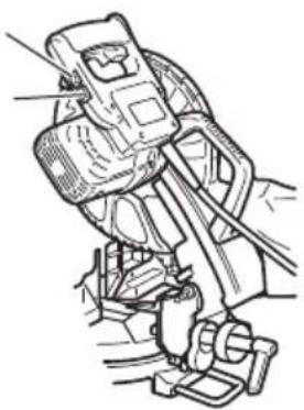
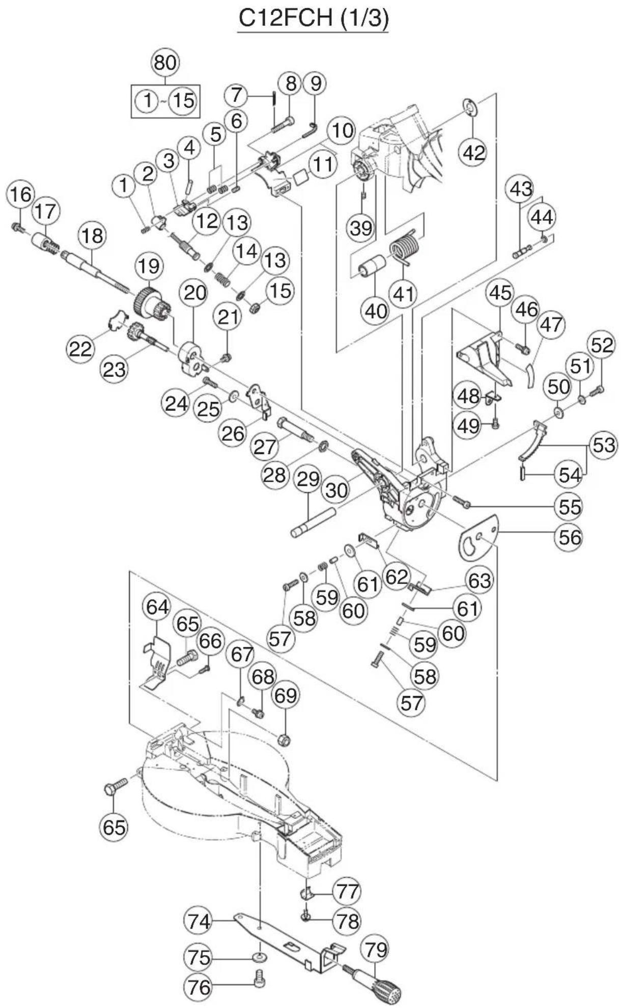
部件名称
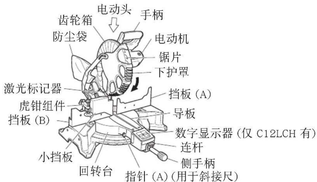
图 1
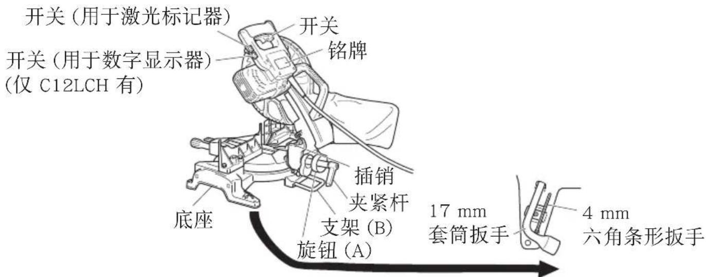
图2
规格
| 最大切割容量高×宽 | 0° | 63.5 mm×200 mm或98 mm×155 mm |
| 斜接45° | 63.5 mm×140 mm | |
| 斜角左45° | 42 mm×200 mm | |
| 复合(斜角左45°,斜接45°) | 42 mm×140 mm | |
| 锯条尺寸(外径×内径×厚度)305 mm×25.4mm×2.7 mm | ||
| 斜接切割角右与左0 | °~52° | |
| 斜面切割角左-3 | °~48° | |
| 复合切割角 | 斜接(右与左)0°~45°斜角(左)0°~45° | |
| 电压220 V | ~ | |
| 输入功率1520 W | ||
| 空载转速4000/min | ||
| 机器尺寸(宽度×深度×高度)625 mm×775 mm×610 mm | ||
| 重量(净重)19.5 kg(C12LCH)/19 kg(C12FCH) | ||
| 数字显示器(仅型号C12LCH有)精度 | ±0.5° | |
| 激光标记器 | 最大输出Po<3 mW | II级激光产品 |
| (Iambda) 654 nm | ||
| 激光介质激光二极管 | ||
标准附件
除了主机(1 台)外,产品包中还包括表中所列的附件。
| 305 mm TCT 锯条(安装在工具上)1 |  | ||
| 防尘袋 | 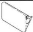 | 1 | |
| 17 mm 套筒扳手 | 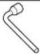 | 1 | |
| 虎钳组件 | 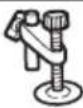 | 1 | |
| 4 mm 六角条形扳手 | 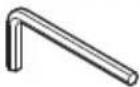 | 1 |
选购件(另售)
| (1) 扩展支架和止动片 | 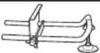 |
| (2) 冠状模塑虎钳组件 (包括冠状模塑止动片(左)) |  |
| (3) 冠状模塑止动片 (左) |  |
| (4) 冠状模塑止动片 (右) |  |
用途
○ 切割各种类型的铝制框架和木材。
打开包装
○ 请小心打开电动工具和所有相关物品(标准附件)的包装。
○ 请仔细核对所有相关物品(标准附件)齐备无误。
作业之前
1. 电源
确认所使用的电源与工具铭牌上标示的规格是否相符。
中文
2. 电源开关
确认电源开关是否切断。若电源开关接通,则插头插入电源插座时电动工具将出其不意地立刻转动,从而招致严重事故。
3. 延伸线缆
若作业场所移到离开电源的地点,应使用容量足够、铠装合适的延伸线缆,并且要尽可能地短些。
4. 当准备运输电动工具时,其主要部件须用锁定插销固定
稍稍移动手柄,可使锁定插销脱落。
在运输过程中,将锁定插销锁在齿轮箱内(图 3)。
5. 将防尘袋安装在电动工具上(第 5 页的图 1)
(1) 防尘袋装满锯末后,锯条旋转时锯末会被吹出防尘袋。
定期检查防尘袋,并在装满前清空。
(2) 在斜角与复合切割时,按照图 4 所示,将防尘袋与底座面成直角安装。
注意!
经常清空防尘袋,以避免管道及下护罩被堵塞。
斜角切割时,锯末的积累速度比正常情况下更快。
6. 安装
保证机器始终固定在工作台上。
请将电动工具安装在水平的工作台上。
选择长度适合工作台厚度的 8 mm 直径螺栓。
螺栓长度至少为 35 mm 加工作台厚度。
例如,在 25 mm 厚度工作台上使用 8 mm×60 mm 螺栓。
手柄
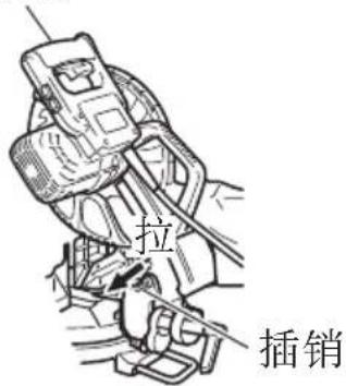
图 3
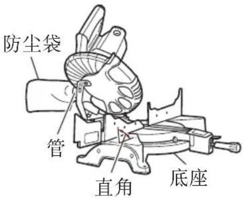
图4
使用前调节电动工具
注意!
在插入电源插头之前,请完成所有必需的调节。
1. 确认下护罩操作顺畅
实际应用
警告!
○ 为避免人员受伤,使用工具时切勿从台上移走工件或把工件放在台上。
○ 使用工具时切勿使四肢进入警告标志旁边的线内,否则可能发生危险(见图 5)。
注意!
○ 在锯条转动时取下或安装工件非常危险。
○ 在进行切割作业时,请从回转台上清除刨花。
○ 如果刨花堆积太多,切割材料的锯条便会暴露。切勿让您的手或其他任何东西靠近暴露的锯条。
- 用虎钳组件紧紧固定要切割的材料,使其在切割中不会移动
- 开关操作
拉动触发器打开开关。松开触发器便可关闭开关。
- 支架 (B) 调节 (图 6)
用所提供的 10 mm 套筒扳手松开 6 mm 螺栓。调节支架(B)直至其底面接触工作台或地面。
- 使用虎钳组件(标准附件)(图 7)
(1) 可拧松 6 mm 翼栓 (A),将虎钳组件安装在左挡板〔挡板 (B)〕或右挡板〔挡板 (A)〕。
(2) 根据工件的高度, 可拧松 6 ~mm 翼栓 (B) 来升高或降低螺栓支架。调节结束后, 须拧紧 6 ~mm 翼栓 (B) 并固定螺栓支架。
(3) 转动上旋钮并将工件固定于适当位置。
警告!
须始终夹紧夹具或虎钳以确保工件固定在挡板上,否则工件可能会从导板上飞出并造成人身伤害。
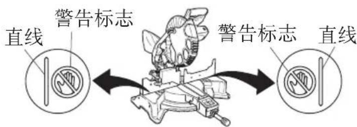
图 5
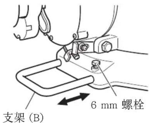
图6
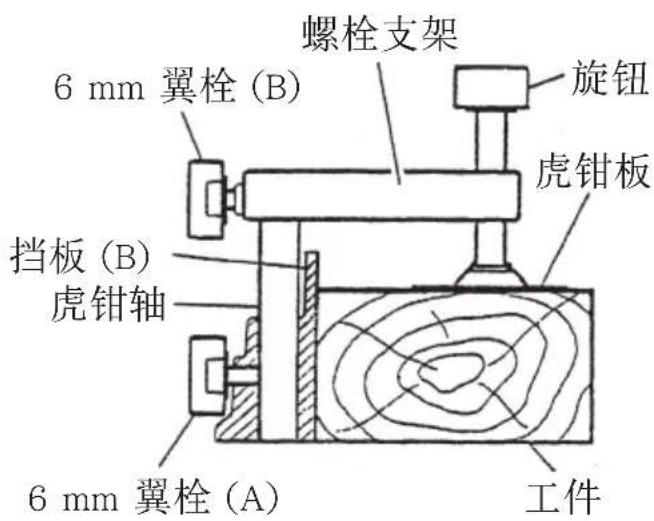
图 7
中文
注意!
须确保虎钳降低进行切割时不会与电动头接触。如果有可能碰到,请松开 6 ~mm 翼栓 (B) 并将虎钳组件移到不会碰到锯片的位置。
5. 确认使用副挡板(图 8)
这个电动工具配备有副挡板。在直接角度切割中,请使用副挡板,这样就可以实现对具有宽大背面的材料进行稳定的切割。在左斜角切割中,请将副挡板升高,如图8所示,然后逆时针旋转。
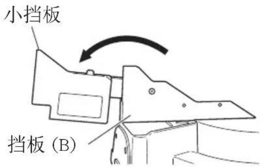
图8
警告!
在左斜角切割中,请逆时针旋转副挡板(图 8)。如果不是逆时针旋转,主体或锯条可能与副挡板接触,从而引起伤害。
6. 使用墨线
在降低电动机部分时,下护罩升起,而出现锯条。
将墨线与锯条对齐。
注意!
在锯条旋转时切勿提起下护罩。
不仅会接触副挡板并影响切割精度,还可能损坏安全罩。
7. 激光线的位置调节
可以方便地在本工具上画墨线以进行激光标记器。通过一个开关点亮激光标记器(图 9)。
在数字显示器开关处在开位置时打开激光标记器开关,点亮激光标记器(C12FCH上只有激光标记器开关)。
根据您所选择的切割方式,激光
开关(用于激光标记器)
开关(用于数字显示器) (仅 C12LCH 有)
natural_image
Technical line drawing of a mechanical assembly with no visible text or symbols图9
线可与切割宽度(锯条)的左侧或位于右侧的墨线对齐。
出厂时激光线被调节至锯条宽度。请按照您的使用选择,进行下列步骤以调节锯条及激光线的位置。
(1) 点亮激光标记器,并在工件上刻出一条约 5 mm 深的凹槽,其高度约为 38 mm ,宽度约 89 mm 。用虎钳把刻有凹槽的工件固定在原位,不要移动。
(2) 然后把 4 mm 六角条形扳手插入齿轮箱侧面的 12 直径孔中, 转动六角套筒固定螺丝以移动激光线。(如顺时针转动六角套筒螺丝, 激光线将向右侧移动, 如逆时针转动, 激光线将向左侧移动。) 如使用时墨线与锯条的左侧对齐, 则将激光线与凹槽的左端对齐 (图 10)。如墨线与锯条的右侧对齐, 则将激光线与凹槽的右侧对齐。
(3) 调节激光线的位置之后,在工件上
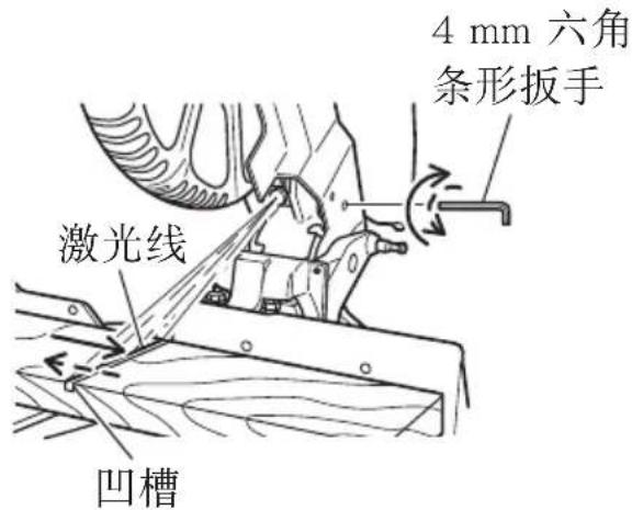
图 10
画出一条直角墨线,并将墨线与激光线对齐。对齐墨线时,应一点一点地滑动工件,并在激光线与墨线重叠的位置将其用虎钳固定。再次进行凹槽操作,并检查激光线的位置。如需改变激光线的位置,则按照第(1)至(3)步再次进行调节。
警告!(图 11与图 12)
○ 在将电源插头插入插座之前,确保主体与激光标记器均关闭。
○ 在使用开关调节激光线的位置时应极为小心,因为操作时电源插头已插入插座。
如在无意中拉动了开关,则锯条会旋转,并造成事故。
○ 不要卸下激光标记器用于其他目的。
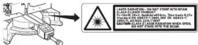
图11
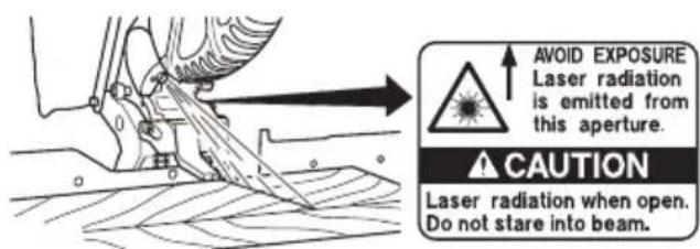
图12
注意!
○ 激光辐射 — 切勿直视光束。
☐ 工作台上有激光辐射。切勿直视光束。眼睛直接暴露于激光束时可能受伤。
○ 切勿拆卸。
☐ 不要猛烈撞击激光标记器(工具主体);否则激光线的位置可能错乱,从而损坏激光标记器并缩短使用寿命。
○ 仅在切割操作中点亮激光标记器。激光标记器点亮时间过长可导致缩短使用寿命。
☐ 如采用本处未说明的控制或调节或执行未说明的其他程序,则可引起有害的辐射暴露。
注:
○ 将墨线与激光线重叠以进行切割。
○ 当墨线与激光线重叠时,光的强弱会发生变化,使切割操作稳定。因为这样可以方便地分辨线的一致性。这确保了最小的切割误差。
中文
○ 在室外或靠近窗户的操作中,可能由于日光的原因而难以看清激光线。此时应移至不直接暴露于日光的地点,并进行操作。
○ 不要拖动电动头后方的电线或用手指、木头等钩住,否则电线可能脱落,使激光标记器不能点亮。
○ 定期检查并确认激光线的位置是否正确。检查方法:在工件上画出一条直角墨线,其高度约 38 mm、宽度约 89 mm,并检查激光线是否与墨线对齐 [墨线与激光线之间的偏离应小于墨线的宽度 (0.5 mm)](图13)。
8. 数字显示器面板 (适用于 C12LCH) (图 14 与图 15)
(1) 打开数字显示器开关,显示斜接和斜角角度均为 ^ ,而不管电动工具的角度为多少。
(2) 将电动工具角度与倾斜角度 ( 0^ ) 和斜接角度 ( 0^ ) 对准,并按住它们的复位按钮至少 0.2 秒。
(3) 在数字显示器开关处在开位置时打开激光标记器开关,点亮激光标记器 (C12FCH 上只有激光标记器开关)。
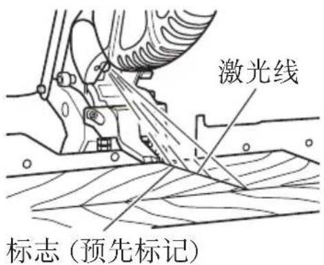
图 13
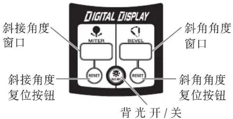
图 14
开关 (用于激光显示器) (仅 C12LCH 有)

natural_image
Technical line drawing of a mechanical component with no visible text or symbols图15
注意!
操作数字显示器面板时,请使电动头部分处在高度上限位置并使锯条停止。
☐ 如果斜接角度数字显示器上显示的数字与前挡板角度不同(例如, 45.0 45.5^ , 31.6^ 32.0^ ),则前挡板可能已经稍微偏离了其正确位置。此时,请执行以下步骤。
(1) 松开侧手柄, 左右移动回转台, 将回转台设置在正确的位置。
(2) 如果显示器上的数字与前挡板角度仍然不匹配,则使回转台回到 0^ 位置。然后松开侧手柄,左右移动回转台,如图 16 所示。在将回转台设置在正确位置 0^ 之后,再按复位按钮。
注:
○ 开始切割前,请将电动工具与斜接角度 (0^) 和斜角角度 (0^) 对准,并按住它们的复位按钮至少0.2秒。
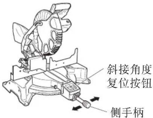
图16
如果在没有将电动工具对准到 0^ 时按下数字显示器的开关,则数字显示器上显示的数字与电动工具角度将不匹配。
○ 如果数字显示器开关关闭,激光标记器将不会亮起。(仅 C12LCH 有)
☐ 请勿在会产生电气噪声的设备,如发电机等附近使用电动工具。电气噪声可能引起数字显示器读数或操作错误。
9. 切割操作
(1) 如图 17 所示, 锯条的宽度为切割宽度。因此, 在需要长度 b 时将工件向右侧滑动 (从操作员的位置看去), 或在需要长度 a 时向左侧滑动。
如使用激光标记器,则将激光线与锯条的左侧对齐,然后将墨线与激光线对齐。
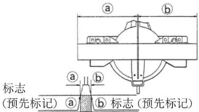
图 17
(2) 锯条达到最大速度后,缓慢地压下手柄,使锯条接近所要切割的材料。
(3) 锯条接触工件后,逐渐压下手柄,以切入工件。
(4) 切人工件至所需的深度后, 关闭电动工具, 让锯条完全停止, 再从工件中提起手柄, 使其回到完全收回位置。
注意!
○ 关于最大切割尺寸,参见“规格”表。
☐ 在手柄上加大压力并不能提高切割速度。相反,压力过大可能使电动机过载与 / 或降低切割效率。
○ 不使用工具时,确认开关已关闭,且电源插头从插座中拔出。
☐ 在从工件中提起手柄前,务必关闭电源并让锯条完全停止。如在锯条仍旋转时提起手柄,则切除的碎片可能卡住锯条,使碎片飞散,造成危险。
每次完成深切割操作后,关闭开关,检查锯条是否停止。然后提起手柄,并使其回到完全收回位置。
☐ 务必从回转台上清除切割材料,然后进行下一步。
中文
- 斜接切割程序
(1) 松开侧手柄,并推动角度止动片的连杆。然后调节回转台,直至指针与斜接尺上的所需设定对齐(图 18)。
(2) 重新拧紧侧手柄,确保回转台处于所需位置。
注:
○ 在 0^ 中心设定的右侧与左侧, 15^ 、 22.5^ 、 31.6^ 与 45^ 设定的位置,回转台均会停止转动。
检查斜接尺与指针的尖端是否对齐。
○ 在斜接尺与指针未对齐、或侧手柄未正确拧紧的情况下使用复合锯,会造成切割精度低下。
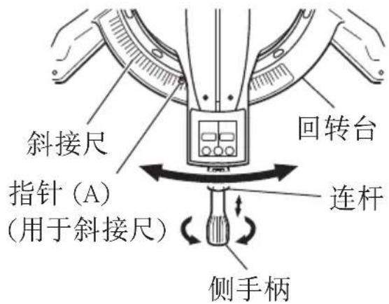
图18
注意!
切勿拆下侧手柄,在无侧手柄的状态下使用此电动工具可能会发生危险。为了防止事故或人体伤害,必须切实拧紧斜面手柄。
- 斜角切割步骤 (图 19)
(1) 拧松夹紧杆并使锯条向左侧倾斜。
(2) 看着角尺和指针将斜角调整为所需设定,然后再固定夹紧杆。
警告!
☐ 工件固定于锯条左侧时,短小的切除部分会停留在锯条右侧。在从工件上抬起手柄之前,必须先切断电源并让锯条完全停止转动。
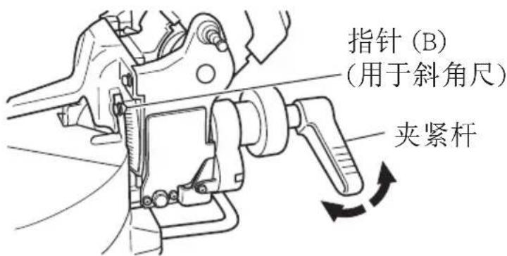
图 19
如果在锯条仍在转动时抬起手柄,被切除的碎片可能会卡住锯条,导致碎片撒开,非常危险。
中途停止斜角切割时,应把电动头拉回初始位置,再开始切割。
如未拉回而从中途开始切割,则可能造成下护罩卡在工件的切割凹槽中,并接触到锯条。
- 斜角角度微调 (图 20 与图 21)
(1) 握紧电动头上的手柄,将它定位在所需的斜角角度。临时紧固夹紧杆。
注意!
如果紧固得不够牢,电动头可能突然移动或滑落,从而引起伤害。请务必牢牢地紧固电动头,使它不会移动。
(2) 握紧手柄并移动旋钮 (A),对斜角角度进行微调。
注:
顺时针转动旋钮(A)将使电动工具向左微调(从前方看)。
逆时针转动旋钮(A)将使电动工具向右微调(从前方看)。
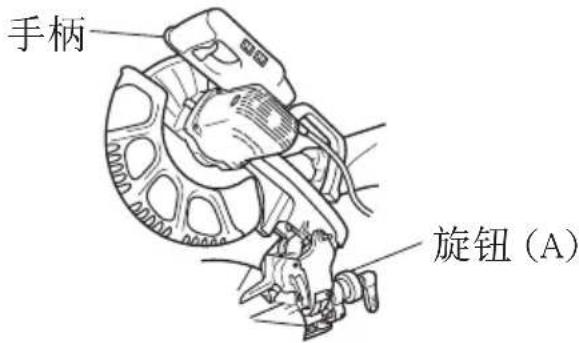
图 20
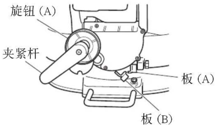
图 21
如果沿不会在板(A)上放置载荷并拉动板(A)的方向上倾斜电动工具, 接触位置将改变, 并且右斜面角度将变成 3^ 。
如果沿不会在板 (B) 上放置载荷并拉动板 (B) 的方向上倾斜电动工具, 接触位置将改变, 并且右斜面角度将变成 48^ 。
(3) 调整到所需角度后,紧固夹紧杆并夹紧电动头。
注意!
须始终检查夹紧杆是否紧固以及电动头是否夹紧。如果没有夹紧电动头就试图进行角度切割,则电动头可能发生意想不到的偏移,从而引起伤害。
- 复合切割步骤
您可以按照以上第 10 和第 11 步的说明进行复合切割。关于复合切割的最大尺寸,参见 “规格” 表。
注意!
在进行复合切割时,必须用右手柄侧来固定工件。在进行复合切割时,切勿将回转台转向右侧,因为锯条可能会接触到固定工件的夹具或虎钳,从而导致人体受伤或工具损坏。
中文
14. 安装支架 (选购件)
在切割操作中,支架可用于延长工件台并使之保持正确位置。
(1) 如图 22 所示, 使用方钢来对齐支架的上缘与底座面。松开 6 ~mm 翼状螺母。旋转高度调节螺栓 6 ~mm , 并调节支架的高度。
(2) 调节后, 旋紧翼状螺母并用 6 ~mm 旋钮螺栓 (选购件) 固定支架。如高度调节螺栓 6 ~mm 的长度不足, 则在其下方放置一块薄板。高度调节螺栓 6 ~mm 的末端不得从支架中突出。
15. 精密切割的止动片(止动片与支架为选购件)
止动片有助于长度为 280 mm 至 450 mm 的连续精密切割。安装止动片时,按照图 23 所示,用 6 mm 翼栓将其与支架连接。
- 确认使用冠状模塑虎钳、冠状模塑止动片(左)与(右)(选购件)
(1) 通过冠状模塑止动片(左)与(右)(选购件),可以方便地切割冠状模塑,而无需倾斜锯条。将其安装在
底座两侧,如图 24 所示。插入后旋紧 6 mm 旋钮螺栓,以固定冠状模塑止动片。
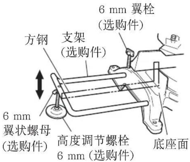
图 22
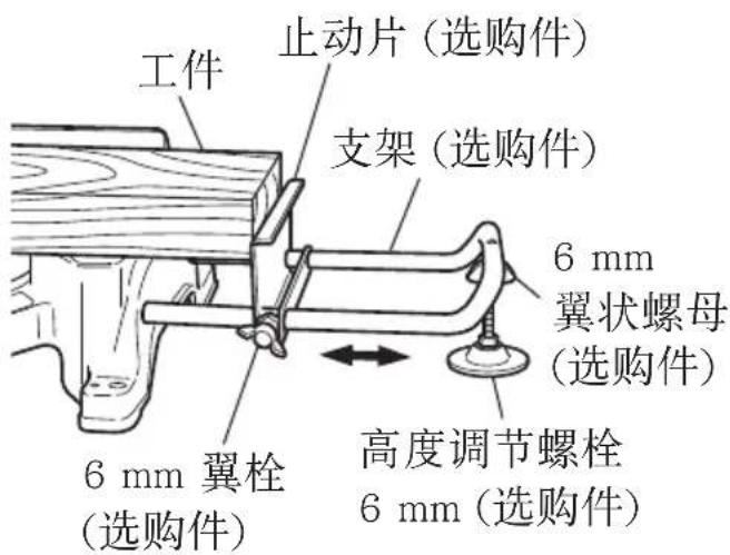
图 23
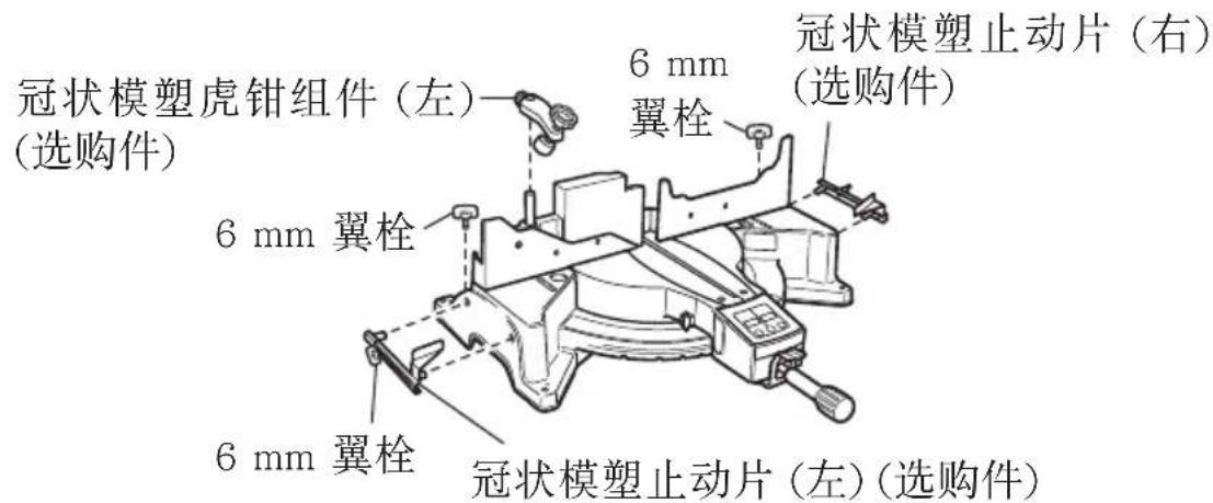
图24
(2) 冠状模塑虎钳 (B) (选购件) 可安装在左挡板 (挡板 (B)) 或右挡板 (挡板 (A)) 上。它可与冠状模塑的斜角结合,并可按下虎钳。
然后按照需要转动上部旋钮,以可靠地连接冠状模塑。如需升高或降低虎钳组件,首先应松开 6 mm 翼栓。
调节高度后,旋紧6 mm翼栓, 然后按照需要旋转上部旋钮, 以可靠地连接冠状模塑(见 图 25)。
放置冠状模塑时,使其壁接触
冠状模塑虎钳组件(左)(选购件)
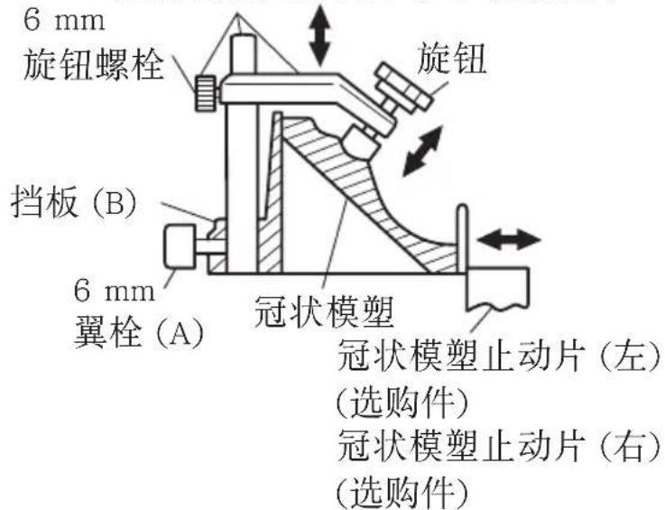
图25
缘贴紧导引挡板,而其顶接触缘贴紧冠状模塑止动片,如图 25 所示。根据冠状模塑的大小来调节冠状模塑止动片。
旋紧 6 mm 翼栓以固定冠状模塑止动片。
警告!
务必夹紧或用虎钳将冠状模塑固定在挡板上,否则冠状模塑可能从台上冲出,而造成人身伤害。
不要进行斜角切割。主体或锯条可能与副挡板接触,从而引起伤害。
注意!
务必确认电动头(见第 5 页的图 1)在降低进行切割时不会接触冠状模塑虎钳组件。如有发生接触的危险,则松开6 mm旋钮螺栓,并移动冠状模塑虎钳组件至不会接触锯条的位置。
锯条的安装和拆卸
警告!
☐ 为了防止事故或人体伤害的发生,在拆卸或安装锯条之前必须首先关闭开关并从电源插座拔下插头。
如进行切割时螺栓未充分旋紧,则螺栓可能松动,锯条可能脱落,而下护罩可能受损,从而引起伤害。
此外,在将电源插头插入插座前,应检查螺栓是否正确旋紧。
☐ 如使用 17 mm 套筒扳手以外的其他工具来连接或拆除螺栓,则会过度或错误地旋紧,从而引起伤害。
中文
- 安装锯条(图 26, 图 27 与图 28)
(1) 旋转下护罩 (塑料) 至上部位置。
(2) 按下主轴锁并用 17 mm 套筒扳手 (标准件) 松开螺栓。
由于螺栓为左侧螺纹,需向右旋转将其松开,如图 27 所示。
注:
如难以按下主轴锁以锁定主轴,则在于主轴锁上施加压力的同时用17 mm套筒扳手(标准件)转动螺栓。
向内按下主轴锁时,锯条主轴被锁定。
(4) 取下螺栓与垫圈 (B)。
(5) 提起下护罩并安装锯条。
警告!
安装锯条时,确认锯条上的旋转指针标志与齿轮箱(见第 5 页的图 1)的转动方向一致。
(6) 仔细清洗垫圈 (B) 与螺栓,并将其安装在锯条主轴上。
(7) 按下主轴锁,并用标准件扳手 (17 mm 套筒扳手) 将螺栓向左转动以旋紧,如图 27 所示。
注意!
○ 安装或取下锯条后,确认主轴锁回到收回位置。
○ 旋紧螺栓,使其在操作中不会松开。
○ 起动电动工具前,确认螺栓已被拧紧。
2. 拆卸锯条
按照上述第 1 段所述安装程序的相反顺序拆卸锯条。
提起下护罩后可方便地拆下锯条。
注意!
切勿试图安装直径在 290 mm - 305 mm 范围以外的锯条。
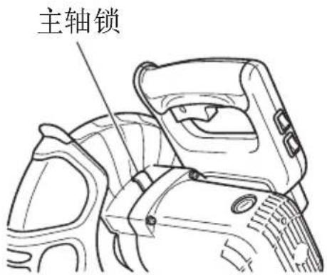
图26
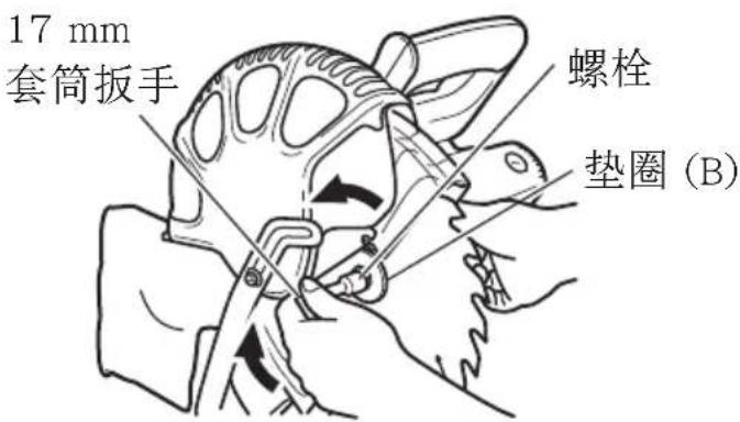
图27
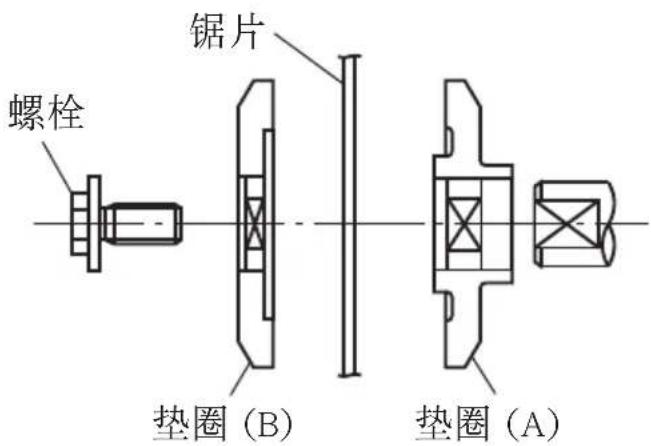
图28
维护和检查
警告!
为了避免发生事故和人体伤害,在对本电动工具进行任何维修和检查之前,必须先确认已关闭开关及已从电源插座拔下电源插头。
1. 检查锯条
发现变质或损坏后应立即更换锯条。
损坏的锯条可引起人身伤害,而磨损的锯条则可导致无效的操作,并可能使电动机过载。
注意!
切勿使用不锋利的锯条。锯条不锋利时,它对于由工具手柄所施加的手部压力的阻力会增加,使电动工具的使用变得不安全。
2. 检查连杆 (图 29 与图 30)
如 M8 六角头螺栓 (2) 松动, 用方钢对齐挡板与锯条的侧面。将锯条与挡板调整至 90 度角后, 旋紧连杆以固定六角头螺栓 (2)。
3. 检查炭刷 (图 31 与图 32)
电动机中的炭刷为消耗品。
如炭刷极度磨损,则可能发生电动机故障。
因此,应定期检查炭刷,并在其磨损至图 31 所示的磨损极限线时予以更换。
此外还应保持炭刷清洁,以保证其在刷握内滑动自如。
用槽口(负号)螺丝起子拆下炭刷盖(见图32),即可方便地拆下炭刷。
- 关于电动机的维护(见第 5 页的图 1) 电动机绕线是本工具的核心。切勿使其暴露于清洗油或水而令绕线受损。
注:
灰尘等在电动机内的积累可引起故障。
使用电动机约 50 小时后,应进行无负载运行,并从电动机后部的风孔中吹入干
燥的空气。此操作对于排除灰尘等较为有效。
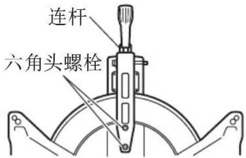
图29
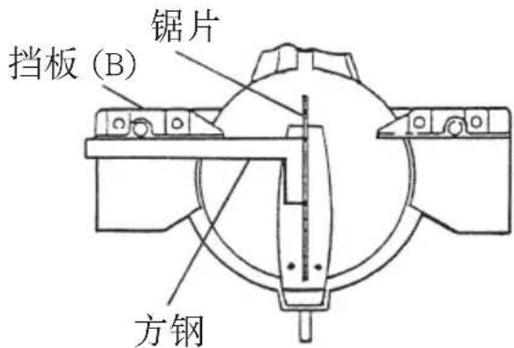
图30
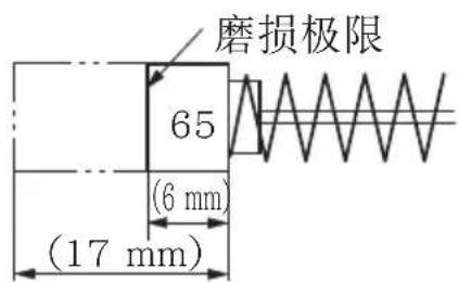
图31
用于起子的凹槽

图32
中文
5. 检查螺丝
定期检查电动工具的各个部件是否存在松动情况。
重新旋紧任何松动的零件。
警告!
为了避免人身伤害,切勿在有松动部件时使用电动工具。
6. 检查下护罩是否操作无误
在每次使用工具之前,测试下护罩(见第 5 页的图 1)以确保其状态良好且运动自如。
除非下护罩操作正常、且机械状态良好,否则切勿使用工具。
7. 储藏
工具使用后,应进行下列各项的检查:
(1) 开关处于关闭 (OFF) 位置。
(2) 电源插座从插座中拔出。
不使用工具时,将其储藏在儿童无法接触的干燥场所。
8. 润滑油
每月应润滑以下滑动面一次,以使电动工具长时间保持良好的工作状态(第5页的图1与第5页的图2)。
请使用推荐的机油。
注油位置:
* 回转支架的转动部分
* 虎钳组件的转动部分
9. 清洁
定期用蘸有肥皂水的湿布除去电动工具表面上(尤其是下护罩内)的碎屑、灰尘以及其他废料。为了避免电动机发生故障,切勿使其接触油或水。
如由于碎屑等粘在激光标记器发光部分的窗口上而无法看清激光线,则用干布或以肥皂水等蘸湿的软布擦拭并清洁窗口。
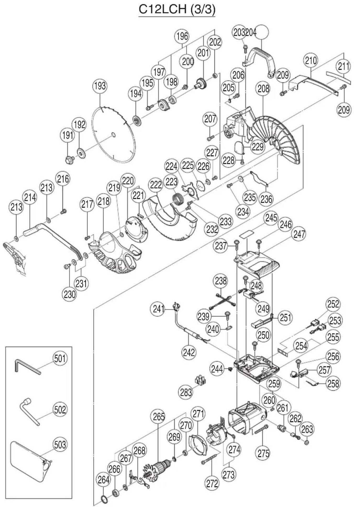
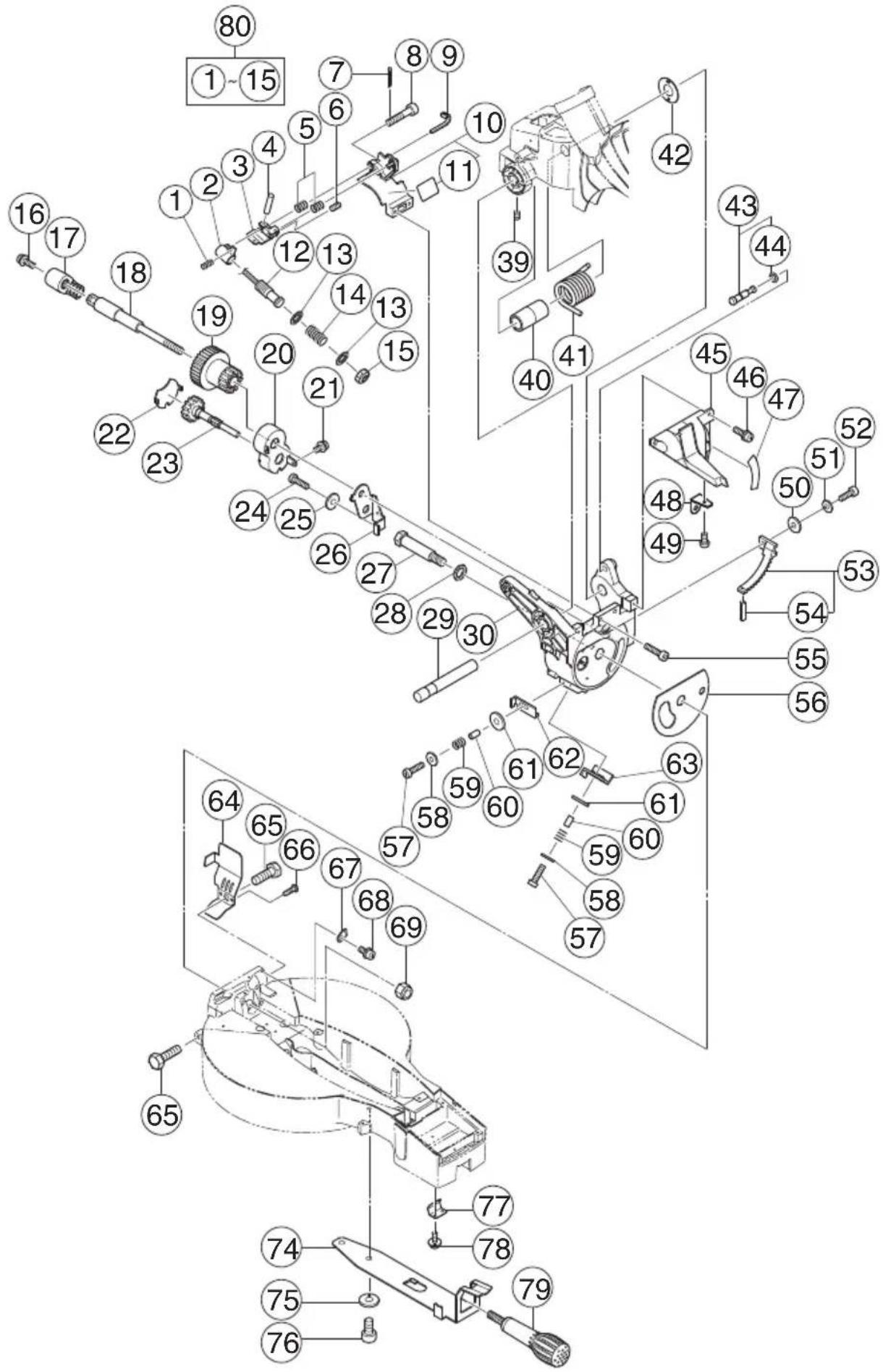
10. 维修零部件一览表
注意!
HiKOKI牌电动工具的修理、更改与检查必须由取得HiKOKI授权的维修中心进行。
特别是激光装置必须由取得激光制造商授权的代理商进行维护。
务必把激光装置的修理交由HiKOKI授权的维修中心进行。
在要求修理或其他维护服务时,最好把本零件清单与工具一同交付HiKOKI授权的维修中心。
在电动工具的操作与维护中,务必遵守各个国家的安全规定与标准。
维修零部件一览表
中文
项目号 代码号 使用数 备注
| 1 323-141 1 | |
| 2 323-137 1 | |
| 3 323-138 1 | |
| 4 949-900 1 D3 × 14 | |
| 5 323-142 2 | |
| 6 962-782 1 M5 × 6 | |
| 7 949-531 1 D2 × 12 | |
| 8 323-144 1 M5 | |
| 9 975-144 1 | |
| 10 323-139 1 “11” | |
| 11——— | 1 |
| 12 323-647 1 | |
| 13 323-143 2 | |
| 14 323-140 1 | |
| 15 323-136 1 | |
| 16 323-208 1 M6 × 20 | |
| 17 322-935 1 | |
| 18 323-665 1 M10 | |
| 19 323-666 1 | |
| 20 323-597 1 | |
| 21 304-043 1 M4 × 10 | |
| 22 323-598 1 | |
| 23 323-599 1 | |
| 24 949-821 1 M5 × 16 | |
| 25 949-454 1 | |
| 26 323-596 1 | |
| 27 322-933 1 | |
| 28 322-934 1 M16 | |
| 29 323-593 1 | |
| 30 323-663 1 | |
| 31 993-539 1 M4 × 16 | |
| 32 980-523 1 | |
| 33 323-600 1 | |
| 34 949-241 1 M5 × 20 | |
| 35 949-432 1 M6 | |
| 36 323-142 2 | |
| 37 323-619 1 | |
| 38 949-216 4 M4 × 10 | |
| 39 307-956 1 M6 × 10 | |
| 40 323-594 1 | |
| 41 323-595 1 |
项目号 代码号 使用数 备注
| 42 323-684 1 |
| 43 302-518 1 “44” |
| 44 984-528 1 P-6 |
| 45 323-601 1 “47-49” |
| 46 990-541 2 M5 × 16 |
| 47 323-602 1 |
| 48 322-963 1 |
| 49 949-214 1 M4 × 6 |
| 50 949-431 1 M5 |
| 51 949-454 1 M5 |
| 52 949-821 1 M5 × 16 |
| 53 323-664 1 “54” |
| 54 949-900 1 D3 × 14 |
| 55 949-660 2 M6 × 20 |
| 56 323-683 1 |
| 57 949-221 2 M4 × 20 |
| 58 949-423 2 M4 |
| 59 323-142 2 |
| 60 303-006 2 D4 × 10 |
| 61 949-432 2 M6 |
| 62 323-662 1 |
| 63 323-661 1 |
| 64 323-659 1 |
| 65 303-409 2 M8 × 25 |
| 66 935-196 2 M4 × 12 |
| 67 322-893 1 |
| 68 304-043 1 M4 × 10 |
| 69 680-418 1 M12 |
| 70 949-217 2 M4 × 12 |
| 71 949-423 2 M4 |
| 72 323-607 1 |
| 74 323-627 1 |
| 75 949-457 2 M8 |
| 76 949-655 2 M8 × 16 |
| 77 323-609 1 |
| 78 307-635 2 M4 × 10 |
| 79 323-680 1 |
| 80 323-646 1 “1-10,12-15” |
项目号 代码号 使用数 备注
| 101 323-658 1 380MM |
| 102 993-539 1 M4 × 16 |
| 103 973-313 1 |
| 104 304-043 1 M4 × 10 |
| 105 993-539 1 M4 × 16 |
| 106 323-650 1 |
| 107 323-624 1 |
| 108 323-142 2 |
| 109 323-619 1 |
| 110 323-622 1 |
| 111 949-432 1 M6 |
| 112 949-241 1 M5 × 20 |
| 113 975-144 1 |
| 114 323-621 1 |
| 115 993-539 1 M4 × 16 |
| 116 323-617 1 |
| 117 323-620 1 160MM |
| 118 975-348 1 M8 |
| 119 318-929 1 |
| 120 304-043 1 M4 × 10 |
| 121 318-927 1 |
| 122 323-648 1 |
| 123 323-649 1 |
| 124 990-541 4 M5 × 16 |
| 125 323-612 1 |
| 126 993-539 4 M4 × 16 |
| 127 323-616 1 |
| 128 323-615 1 “127” |
| 129 323-608 1 |
| 130 321-672 10 D2 × 6 |
| 131 323-613 1 |
| 132 323-611 1 |
| 133 323-614 1 |
| 134 323-618 1 |
| 135 323-677 1 “136-142” |
| 136 323-678 1 |
| 137 301-806 1 M6 × 15 |
| 138——1 |
| 139 949-432 1 M6 |
| 140 302-532 1 |
| 141 949-216 1 M4 × 10 |
项目号 代码号 使用数 备注
| 142 322-954 1 |
| 143 311-144 1 M6 |
| 144 304-043 1 M4 × 10 |
| 145 323-631 1 |
| 146 323-630 1 “147” |
| 147——1 |
| 148 301-806 1 M6 × 15 |
| 149 949-678 4 M8 × 35 |
| 150 949-457 4 M8 |
| 151 949-433 4 M8 |
| 152 323-629 1 |
| 153 323-685 1 M6 × 30 |
| 154 323-625 3 |
| 155 302-317 2 M5 × 16 |
| 156 949-431 2 M5 |
| 157 323-604 1 |
| 158 323-603 1 |
| 159 322-910 1 |
| 160 949-610 1 M6 × 10 |
| 161 987-512 1 M5 × 16 |
| 162 323-605 1 |
| 163 323-623 1 |
| 164 949-215 1 M4X × 8 |
| 165 323-628 1 |
| 168 323-606 4 |
| 169——1“168,171,172” |
| 170 323-626 1 |
| 171——1 |
| 172 323-656 1 |
| 173 323-610 1 “125,130-133” |
| 601 323-546 1 “602-605” |
| 602 301-806 1 M6 × 15 |
| 603——1 |
| 604 321-390 1 |
| 605 323-682 1 M6 × 85 |
| 606 323-547 1 “607-610” |
| 607 323-682 2 M6 × 85 |
| 608 321-390 1 |
| 609——1 |
| 610 301-806 1 M6 × 15 |
| 611 323-657 1 “612-617” |
项目号 代码号 使用数 备注
| 612 321-549 1 | |
| 613 949-313 1 M6 | |
| 614 949-556 1 M6 | |
| 615 322-047 1 | |
| 616 949-425 1 M6 | |
| 617 323-681 1 M6 × 105 | |
| 618 974-561 1 | |
| 619 949-404 1 M6X × 20 | |
| 620 323-545 1 “601,621” | |
| 621 322-957 1 “622-628” | |
| 622 321-551 1 M10 × 54 | |
| 623 998-836 1 M6 × 11 | |
| 624——1 | |
| 625 306-985 1 | |
| 626 964-851 1 | |
| 627 304-043 1 M4 × 10 | |
| 628 318-967 1 | |
| 629 323-523 1 | “607,611,618,619” |
中文
项目号 代码号 使用数 备注
| 191 988-101 1 M10 | |
| 192 323-652 1 | |
| 193—— | $05MM-D25.4-NT120 |
| 194 323-651 1 | |
| 195 323-208 2 M6 × 20 | |
| 196 323-639 1 | “197,198,200-202” |
| 197 323-641 1 | |
| 198 320-3VV 1 | 6203VVCMPS2L |
| 200 304-043 2 M4 × 10 | |
| 201 323-640 1 | |
| 202 608-VVM 1 | 608VVC2PS2L |
| 203 323-208 2 M6 × 20 | |
| 204 322-924 1 | |
| 205 980-523 1 | |
| 206 935-196 1 M4 × 12 | |
| 207 949-755 1 M6 × 16 | |
| 208 323-638 1 | |
| 209 993-539 2 M4 × 16 | |
| 210 323-653 1 | “211” |
| 211 323-654 1 | |
| 213 322-948 2 M7 | |
| 214 323-674 1 | |
| 216 322-950 1 M6 | |
| 217 318-363 1 M4 × 10 | |
| 218 323-668 1 | |
| 219 949-454 1 M5 | |
| 220 323-672 1 | “221” |
| 221 323-673 1 | |
| 222 323-667 1 | |
| 223 323-671 1 | |
| 224 323-669 1 | |
| 225 323-670 1 | |
| 226 949-454 1 M5 | |
| 227 949-236 1 M5 × 10 | |
| 228 949-216 1 M4 × 10 | |
| 229 322-926 1 | |
| 230 322-947 1 M5 | |
| 231 322-938 2 M10 | |
| 232 949-215 3 M4 × 8 | |
| 233 323-040 3 M5 × 10 | |
| 234 323-040 2 M5 × 10 | |
| 235 949-431 1 M5 |
项目号 代码号 使用数 备注
| 236 323-675 1 | |
| 237 307-028 2 D4 × 25 | |
| 238 323-632 1 | |
| 239 984-750 2 D4 × 16 | |
| 240 937-631 1 | |
| 241____ | 1 |
| 242 940-778 1 D10.7 | |
| 244 319-349 1 | |
| 245____ | 1 |
| 246 301-653 4 D4 × 20 | |
| 247 323-642 1 | |
| 248 984-750 1 D4 × 16 | |
| 249 322-911 1 | |
| 250 301-653 2 D4 × 20 | |
| 251 323-645 1 | |
| 252 323-634 1 | |
| 253 323-635 1 | |
| 254 323-644 1 | |
| 255 323-643 1 | “254” |
| 256 984-750 1 D4 × 16 | |
| 257 320-950 1 | |
| 258 323-633 1 | |
| 259 322-914 1 | “260,261” |
| 260 938-477 2 M5 × 8 | |
| 261 938-241 2 | |
| 262 999-065 2 | |
| 263 945-161 2 | |
| 264 303-792 1 | |
| 265____ | “266,267,269,270” |
| 266 620-2VV 1 | 6202VVCMPS2L |
| 267 980-700 1 | |
| 268 323-637 1 | |
| 269 302-428 1 | |
| 270 600-0VV 1 | 6000VVCMPS2L |
| 271 322-915 1 | |
| 272 953-174 2 D5 × 55 | |
| 273____ | “274” |
| 274 937-623 2 | |
| 275 322-123 4 M5 × 40 | |
| 283 958-308Z 1 | |
| 501 944-458 1 4MM | |
| 502 985-051 1 17MM | |
| 503 322-955 1 |
中文
项目号 代码号 使用数 备注
| 1 323-141 1 |
| 2 323-137 1 |
| 3 323-138 1 |
| 4 949-900 1 D3 × 14 |
| 5 323-142 2 |
| 6 962-782 1 M5 × 6 |
| 7 949-531 1 D2 × 12 |
| 8 323-144 1 M5 |
| 9 975-144 1 |
| 10 323-139 1 "11" |
| 11____1 |
| 12 | 323-647 | 1 |
| 13 | 323-143 | 2 |
| 14 | 323-140 | 1 |
| 15 | 323-136 | 1 |
| 16 | 323-208 | 1 | M6 × 20 |
| 17 | 322-935 | 1 |
| 18 | 323-665 | 1 | M10 |
| 19 | 323-666 | 1 |
| 20 | 323-597 | 1 |
| 21 | 304-043 | 1 | M4 × 10 |
| 22 | 323-598 | 1 |
| 23 | 323-599 | 1 |
| 24 | 949-821 | 1 | M5 × 16 |
| 25 | 949-454 | 1 |
| 26 | 323-596 | 1 |
| 27 | 322-933 | 1 |
| 28 | 322-934 | 1 | M16 |
| 29 | 323-593 | 1 |
| 30 | 323-663 | 1 |
| 39 | 307-956 | 1 | M6 × 10 |
| 40 | 323-594 | 1 |
| 41 | 323-595 | 1 |
| 42 | 323-684 | 1 |
| 43 302-518 1 "44" |
| 44 | 984-528 | 1 | P-6 |
| 45 | 323-719 | 1 | "47-49" |
| 46 | 990-541 | 2 | M5 × 16 |
| 47 | 323-697 | 1 |
| 48 | 322-963 | 1 |
| 49 | 949-214 | 1 | M4 × 6 |
项目号 代码号 使用数 备注
| 50 949-431 1 M5 |
| 51 949-454 1 M5 |
| 52 949-821 1 M5 × 16 |
| 53 323-664 1 “54” |
| 54 949-900 1 D3 × 14 |
| 55 949-660 2 M6 × 20 |
| 56 323-683 1 |
| 57 949-221 2 M4 × 20 |
| 58 949-423 2 M4 |
| 59 323-142 2 |
| 60 303-006 2 D4 × 10 |
| 61 949-432 2 M6 |
| 62 323-662 1 |
| 63 323-661 1 |
| 64 323-659 1 |
| 65 303-409 2 M8 × 25 |
| 66 935-196 2 M4 × 12 |
| 67 322-893 1 |
| 68 304-043 1 M4 × 10 |
| 69 680-418 1 M12 |
| 74 323-627 1 |
| 75 949-457 2 M8 |
| 76 949-655 2 M8 × 16 |
| 77 323-609 1 |
| 78 307-635 2 M4 × 10 |
| 79 323-680 1 |
| 80 323-646 1 “1-10,12-15” |
中文
项目号 代码号 使用数 备注
| 104 949-216 1 M4 × 10 |
| 105 954-878 1 M4 × 16 |
| 106 323-650 1 |
| 107 323-624 1 |
| 118 975-348 1 M8 |
| 119 318-929 1 |
| 120 304-043 1 M4 × 10 |
| 121 318-927 1 |
| 122 323-648 1 |
| 123 323-649 1 |
| 124 990-541 4 M5 × 16 |
| 126 993-539 4 M4 × 16 |
| 132 323-693 1 |
| 135 323-677 1 “136-142” |
| 136 323-678 1 |
| 137 301-806 1 M6 × 15 |
| 138——— 1 |
| 139 949-432 1 M6 |
| 140 302-532 1 |
| 141 949-216 1 M4 × 10 |
| 142 322-954 1 |
| 143 311-144 1 M6 |
| 144 304-043 1 M4 × 10 |
| 145 323-631 1 |
| 146 323-630 1 “147” |
| 147——— 1 |
| 148 301-806 1 M6 × 15 |
| 149 949-678 4 M8 × 35 |
| 150 949-457 4 M8 |
| 151 949-433 4 M8 |
| 152 323-629 1 |
| 153 323-685 1 M6 × 30 |
| 154 323-625 3 |
| 159 322-910 1 |
| 160 949-610 1 M6 × 10 |
| 161 987-512 1 M5 × 16 |
| 162 323-605 1 |
| 165 323-628 1 |
| 168 323-606 4 |
| 169——— 1 “168,171,172” |
| 170 323-626 1 |
项目号 代码号 使用数 备注
| 171 | 1 |
| 172 323-692 1 | |
| 601 323-546 1 “602-605” | |
| 602 301-806 1 M6 × 15 | |
| 603 | 1 |
| 604 321-390 1 | |
| 605 323-682 1 M6 × 85 | |
| 606 323-547 1 “607-610” | |
| 607 323-682 2 M6 × 85 | |
| 608 321-390 1 | |
| 609 | 1 |
| 610 301-806 1 M6 × 15 | |
| 611 323-657 1 “612-617” | |
| 612 321-549 1 | |
| 613 949-313 1 M6 | |
| 614 949-556 1 M6 | |
| 615 322-047 1 | |
| 616 949-425 1 M6 | |
| 617 323-681 1 M6 × 105 | |
| 618 974-561 1 | |
| 619 949-404 1 M6X × 20 | |
| 620 323-545 1 “601,621” | |
| 621 322-957 1 “622-628” | |
| 622 321-551 1 M10 × 54 | |
| 623 998-836 1 M6 × 11 | |
| 624 | 1 |
| 625 306-985 1 | |
| 626 964-851 1 | |
| 627 304-043 1 M4 × 10 | |
| 628 318-967 1 | |
| 629 323-523 1 | “607,611,618,619” |
中文
项目号 代码号 使用数 备注
| 191988-1011M10 | |
| 192323-6521 | |
| 193—— | 1305MM-D25.4-NT120 |
| 194323-6511 | |
| 195 323-208 2 M6 × 20 | |
| 196323-6391 | “197,198,200-202” |
| 197323-6411 | |
| 198620-3VV1 | 6203VVCMPS2L |
| 200 304-043 2 M4 × 10 | |
| 201323-6401 | |
| 202608-VVM1 | 608VVC2PS2L |
| 203 323-208 2 M6 × 20 | |
| 204322-9241 | |
| 205980-5231 | |
| 206 935-196 1 M4 × 12 | |
| 207 949-755 1 M6 × 16 | |
| 208323-6381 | |
| 209 993-539 2 M4 × 16 | |
| 210323-6531“211” | |
| 211323-6541 | |
| 213322-9482M7 | |
| 214323-6741 | |
| 216322-9501M6 | |
| 217 318-363 1 M4 × 10 | |
| 218323-6981 | |
| 219949-4541M5 | |
| 220323-6721“221” | |
| 221323-6731 | |
| 222323-6671 | |
| 223323-6711 | |
| 224323-6691 | |
| 225323-6701 | |
| 226949-4541M5 | |
| 227 949-236 1 M5 × 10 | |
| 228 304-043 1 M4 × 10 | |
| 229322-9261 | |
| 230322-9471M5 | |
| 231322-9382M10 | |
| 232 949-215 3 M4 × 8 | |
| 233 323-040 3 M5 × 10 | |
| 234 323-040 2 M5 × 10 |
项目号 代码号 使用数 备注
| 235949-4311M5 | |
| 236323-6751 | |
| 237 307-028 2 D4 × 25 | |
| 239 984-750 2 D4 × 16 | |
| 240937-6311 | |
| 241______ | 1 |
| 242940-7781D10.7 | |
| 244319-3491 | |
| 245______ | 1 |
| 246 301-653 4 D4 × 20 | |
| 247323-6421 | |
| 248 984-750 1 D4 × 16 | |
| 249322-9111 | |
| 250 301-653 2 D4 × 20 | |
| 251323-6451 | |
| 252323-6341 | |
| 254323-6951 | |
| 255323-6941“254” | |
| 256 984-750 1 D4 × 16 | |
| 257320-9501 | |
| 258323-6331 | |
| 259322-9141“260,261” | |
| 260 938-477 2 M5 × 8 | |
| 261938-2412 | |
| 262999-0652 | |
| 263945-1612 | |
| 264303-7921 | |
| 265______ | 1‘266,267,269,270” |
| 266620-2VV1 | 6202VVCMPS2L |
| 267980-7001 | |
| 268323-6371 | |
| 269302-4281 | |
| 270600-0VV1 | 6000VVCMPS2L |
| 271322-9151 | |
| 272 953-174 2 D5 × 55 | |
| 273______1 “274” | |
| 274937-6232 | |
| 275 322-123 4 M5 × 40 | |
| 283958-308Z1 | |
| 501944-45814MM | |
| 502985-051117MM | |
| 503322-9551 |
CONTENTS
GENERAL OPERATIONAL PRECAUTIONS ....34
PRECAUTIONS ON USING COMPOUND MITER SAW 36
SYMBOL....37
NAME OF PARTS....38
SPECIFICATIONS....39
STANDARD ACCESSORIES 39
OPTIONAL ACCESSORIES (sold separately)......40
APPLICATION 40
UNPACKING 40
PRIOR TO OPERATION 40
ADJUSTING THE POWER TOOL PRIOR TO USE 41
PRACTICAL APPLICATIONS 41
MOUNTING AND DISMOUNTING SAW BLADE ....50
MAINTENANCE AND INSPECTION 52
SERVICE PARTS LIST 55
GENERAL OPERATIONAL PRECAUTIONS
WARNING!
When using electric tools, basic safety precautions should always be followed to reduce the risk of fire, electric shock and personal injury, including the following.
Read all these instructions before operating this product and save these instructions. For safe operations:
-
Keep work area clean. Cluttered areas and benches invite injuries.
-
Consider work area environment. Do not expose power tools to rain. Do not use power tools in damp or wet locations. Keep work area well lit. Do not use power tools where there is risk to cause fire or explosion.
-
Guard against electric shock. Avoid body contact with earthed or grounded surfaces (e.g. pipes, radiators, ranges, refrigerators).
-
Keep children and infirm persons away. Do not let visitors touch the tool or extension cord. All visitors should be kept away from work area.
-
Store idle tools. When not in use, tools should be stored in a dry, high or locked up place, out of reach of children and infi rm persons.
-
Do not force the tool. It will do the job better and safer at the rate for which it was intended.
-
Use the right tool. Do not force small tools or attachments to do the job of a heavy duty tool. Do not use tools for purposes not intended; for example, do not use circular saw to cut tree limbs or logs.
-
Dress properly. Do not wear loose clothing or jewelry, they can be caught in moving parts. Rubber gloves and non-skid footwear are recommended when working outdoors. Wear protecting hair covering to contain long hair.
-
Use eye protection. Also use face or dust mask if the cutting operation is dusty.
-
Connect dust extraction equipment.
Cutting operation by this compound miter saw may produce considerable amount of dust from extraction duct on fi xed guard.
(Dust material: Wood or Aluminium)
If devices are provided for the connection of dust extraction and collection facilities ensure these are connected and properly used.
-
Do not abuse the cord. Never carry the tool by the cord or yank it to disconnect it from the receptacle. Keep the cord away from heat, oil and sharp edges.
-
Secure work. Use clamps or a vise to hold the work. It is safer than using your hand and it frees both hands to operate tool.
-
Do not overreach. Keep proper footing and balance at all times.
-
Maintain tools with care. Keep cutting tools sharp and clean for better and safer performance. Follow instructions for lubrication and changing accessories. Inspect tool cords periodically and if damaged, have it repaired by authorized service center. Inspect extension cords periodically and replace, if damaged. Keep handles dry, clean, and free from oil and grease.
-
Disconnect tools. When not in use, before servicing, and when changing accessories such as blades, bits and cutters.
-
Remove adjusting keys and wrenches. Form the habit of checking to see that keys and adjusting wrenches are removed from the tool before turning it on.
-
Avoid unintentional starting. Do not carry a plugged-in tool with a finger on the switch. Ensure switch is off when plugging in.
-
Use outdoor extension leads. When tool is used outdoors, use only extension cords intended for outdoor use.
-
Stay alert. Watch what you are doing. Use common sense. Do not operate tool when you are tired.
-
Check damaged parts. Before further use of the tool, a guard or other part that is damaged should be carefully checked to determine that it will operate properly and perform its intended function. Check for alignment of moving parts, free running of moving parts, breakage of parts, mounting and any other conditions that may affect its operation. A guard or other part that is damaged should be properly repaired or replaced by an authorized service center unless otherwise indicated in this handling instructions. Have defective switches replaced by an authorized service center. Do not use the tool if the switch does not turn it on and off.
-
Warning
The use of any accessory or attachment, other than those recommended in this handling instructions, may present a risk of personal injury.
- Have your tool repaired by a qualified person.
This electric tool is in accordance with the relevant safety requirements. Repairs should only be carried out by qualified persons using original spare parts. Otherwise this may result in considerable danger to the user.
PRECAUTIONS ON USING COMPOUND MITER SAW
- Keep the floor area around the machine level. Well maintained and free of loose materials e.g. chips and cut-off s.
- Provide adequate general or localized lighting.
- Do not use power tools for applications other than those specified in the handling instructions.
- Repairing must be done only by authorized service facility. Manufacturer is not responsible for any damages and injuries due to the repair by the unauthorized persons as well as the mishandling of the tool.
- To ensure the designed operational integrity of power tools, do not remove installed covers or screws.
- Do not touch movable parts or accessories unless the power source has been disconnected.
- Use your tool at lower input than specified on the nameplate; otherwise, the finish may be spoiled and working efficiency reduced due to motor overload.
- Do not wipe plastic parts with solvent. Solvents such as gasoline, thinner, benzine, carbon tetrachloride, alcohol, may damage and crack plastic parts. Do not wipe them with such solvent. Clean plastic parts with a soft cloth lightly dampened with soapy water.
- Use only original HiKOKI replacement parts.
- This tool should only be disassembled for replacement of carbon brushes.
- The exploded assembly drawing on this handling instructions should be used only for authorized service facility.
- Never cut ferrous metals or masonry.
- Adequate general or localized lighting is provided. Stock and finished workpieces are located close to the operators normal working position.
- Wear suitable personal protective equipment when necessary, this could include:
Hearing protection to reduce the risk of induced hearing loss.
Eye protection to reduce the risk of injuring an eye.
Respiratory protection to reduce the risk of inhalation of harmful dust.
Gloves for handling saw blades (saw blades shall be carried in a holder wherever practicable) and rough material. - The operator is adequately trained in the use, adjustment and operation of the machine.
- Refrain from removing any cut-offs or other parts of the workpiece from the cutting area whilst the machine is running and the saw head is not in the rest position.
- Never use the compound miter saw with its lower guard locked in the open position.
- Ensure that the lower guard moves smoothly.
- Do not use the saw without guards in position, in good working order and properly maintained.
- Use correctly sharpened saw blades. Observe the maximum speed marked on the saw blade.
-
Do not use saw blades which are damaged or deformed.
-
Do not use saw blades manufactured from high speed steel.
-
Use only saw blades recommended by HiKOKI.
-
The saw blades should be from 290 mm to 305 mm external diameter ranges.
-
Select the correct saw blade for the material to be cut.
-
Never operate the compound miter saw with the saw blade turned upward or to the side.
-
Ensure that the workpiece is free of foreign matter such as nails.
-
Replace the table insert when worn.
-
Do not use the saw to cut other than aluminium, wood or similar materials.
-
Do not use the saw to cut other materials than those recommended by the manufacturer.
-
Blade replacement procedure, including the method for repositioning and a warning that this must be carried out correctly.
-
Connect the compound miter saw to a dust collecting device when sawing wood.
-
Take care when slotting.
-
When transporting or carrying the tool, do not grasp the holder. Grasp the handle instead of the holder.
-
Start cutting only after motor revolution reaches maximum speed.
-
Promptly cut OFF the switch when abnormality observed.
-
Shut off power and wait for saw blade to stop before servicing or adjusting tool.
-
During a miter or bevel cut the blade should not be lifted until it has stopped rotation completely.
-
Take all the possibility of residual risks in cutting operation into your consideration, such as the laser radiation to your eyes, the inadvertent access to moving parts on slide mechanical parts on machine and so on.
SYMBOL
WARNING
The following show symbols used for the machine. Be sure that you understand their meaning before use.

To reduce the risk of injury, user must read instruction manual.
NAME OF PARTS
Fig. 1
Fig. 2
SPECIFICATIONS
| Max. Cutting Capacity Height × Width | 0° | 63.5 mm × 200 mm or 98 mm × 155 mm | |
| Miter 45° 63.5 mm × 140 mm | |||
| Bevel Left 45° 42 mm × 200 mm | |||
| Compound (Bevel Left 45°, Miter 45°) 42 mm × 140 mm | |||
| Saw Blade Dimensions (oD × iD × Thickness) 305 mm × 25.4 mm × 2.7 mm | |||
| Miter Cutting Angle Right and Left 0° – 52° | |||
| Bevel Cutting Angle Left | -3° – 48° | ||
| Compound Cutting Angle | Miter (Right and Left) 0° – 45° Bevel (Left) 0° – 45° | ||
| Voltage | 220V~ | ||
| Power Input 1520 W | |||
| No-Load Speed 4000 /min | |||
| Machine Dimensions (Width × Depth × Height) 625 mm × 775 mm × 610 mm | |||
| Weight (Net) 19.5 kg (C12LCH) / 19 kg (C12FCH) | |||
| Digital Display (Only Model C12LCH) | Precision ±0.5° | ||
| Laser Marker | Maximum output | Po<3 mW Class II Laser Product | |
| (lambda) 654 nm | |||
| Laser medium | Laser Diode | ||
STANDARD ACCESSORIES
In addition to the main unit (1 unit), the package contains the accessories listed in the below.
| 305 mm TCT Saw blade (mounted on tool) |  | 1 |
| Dust bag |  | 1 |
| 17 mm Box wrench | 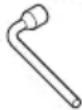 | 1 |
| Vise Assembly | 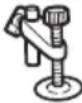 | 1 |
| 4 mm Hex. bar wrench | 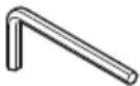 | 1 |
OPTIONAL ACCESSORIES (sold separately)
| (1) Extension Holder and Stopper | 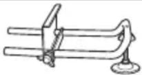 |
| (2) Crown molding Vise Ass'y (Include Crown molding Stopper (L)) |  |
| (3) Crown molding Stopper (L) |  |
| (4) Crown molding Stopper (R) |  |
APPLICATION
○ Cutting various types of aluminium sash and wood.
UNPACKING
○ Carefully unpack the power tool and all related items (standard accessories).
☐ Check carefully to make certain all related items (standard accessories) are present.
PRIOR TO OPERATION
- Power source
Ensure that the power source to be utilized conforms to the power requirements specified on the product nameplate.
- Power switch
Ensure that the power switch is in the OFF position. If the plug is connected to a receptacle while the trigger switch is in the ON position, the power tool will start operating immediately, inviting serious accident.
- Extension cord
When the work area is removed from the power source, use an extension cord of sufficient thickness and rated capacity. The extension cord should be kept as short as practicable.
- When the power tool is prepared for shipping, its main parts are secured by a locking pin
Move the handle slightly so that the locking pin can be disengaged.
During transport, lock the locking pin into the gear case (Fig. 3).
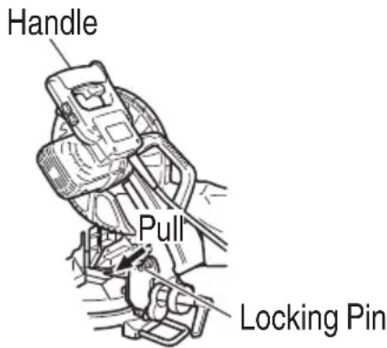
Fig. 3
- Attach the dust bag to the main unit (Fig. 1 on page 38)
(1) When the dust bag has become full of sawdust, dust will be blown out of the dust bag when the saw blade rotates.
Check the dust bag periodically and empty it before it becomes full.
(2) During bevel and compound cutting, attach the dust bag at a right angle to the base surface as shown in Fig. 4.
CAUTION
Empty the dust bag frequently to prevent the duct and the lower guard from becoming clogged.
Sawdust will accumulate more quickly than normal during bevel cutting.
Fig. 4
- Installation
Ensure that the machine is always fixed to bench.
Attach the power tool to a level, horizontal work bench.
Select 8 mm diameter bolts suitable in length for the thickness of the work bench.
Bolt length should be at least 35 mm plus the thickness of the work bench.
For example, use 8 mm × 60 mm bolts for a 25 mm thick work bench.
ADJUSTING THE POWER TOOL PRIOR TO USE
CAUTION
Make all necessary adjustments before inserting the plug in the power source.
- Check to see that the lower guard operates smoothly
PRACTICAL APPLICATIONS
WARNING
○ To avoid personal injury, never remove or place a workpiece on the table while the tool is being operated.
Never place your limbs inside of the line next to warning sign while the tool is being operated. This may cause hazardous conditions (see Fig. 5).

Fig. 5
CAUTION
○ It is dangerous to remove or install the workpiece while the saw blade is turning.
When sawing, clean off the shavings from the turntable.
○ If the shavings accumulate too much, the saw blade from the cutting material will be exposed. Never subject your hand or anything else to go near the exposed blade.
-
Tightly secure the material by vise assembly to be cut so that it does not move during cutting
-
Switch operation Pulling the trigger turns the switch on. Releasing the trigger turns the switch off.
English
3. Holder (B) adjustment (Fig. 6)
Loosen the 6 mm bolt with the supplied 10 mm box wrench. Adjust the holder (B) until its bottom surface contacts the bench or the floor surface.
4. Using the Vise Assembly (Standard accessory) (Fig. 7)
(1) The vise assembly can be mounted on either the left fence {Fence (B)} or the right fence {Fence (A)} by loosening the 6 mm wing bolt (A).
(2) The screw holder can be raised or lowered according to the height of the workpiece by loosening the 6 mm wing bolt (B). After the adjustment, firmly tighten the 6 mm wing bolt (B) and fix the screw holder.
(3) Turn the upper knob and securely fix the workpiece in position.
WARNING
Always firmly clamp or vise to secure the workpiece to the fence; otherwise the workpiece might be thrust from the table and cause bodily harm.
CAUTION
Always confi rm that the motor head does not contact the vise assembly when it is lowered for cutting. If there is any danger that it may do so, loosen the 6 mm wing bolt and move the vise assembly to a position where it will not contact the saw blade.
5. Confirmation for use of sub fence (Fig. 8)
This power tool is equipped with a sub fence. In the case of direct angle cutting use the sub fence. Then, you can realize stable cutting of the material with a wide back face. In the case of left bavel cutting, raise the sub fence up as illustrated in Fig. 8 and then turn it counterclockwise.
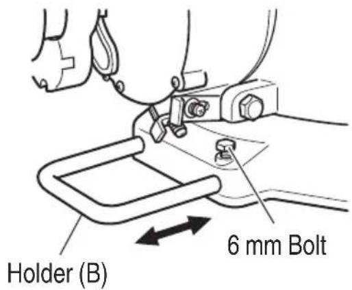
Fig. 6
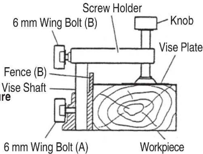
Fig. 7
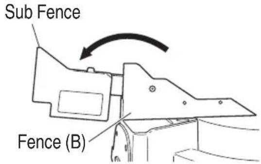
Fig. 8
WARNING
In the case of left bevel cutting, turn the sub fence counterclockwise (Fig. 8).
Unless it is turned counterclockwise, the main body or saw blade may contact the sub fence, resulting in an injury.
6. Using an ink line
Upon lowering the motor section, the lower guard is raised and the saw blade appears.
Align the ink line with the saw blade.
CAUTION
Never lift the lower guard while the saw blade is rotating.
The sub fence will not only make contact and adversely affect cutting accuracy, this could also result in damage to the guard.
7. Position adjustment of laser line
Ink lining can be easily made on this tool to the laser marker. A switch lights up the laser marker (Fig. 9).
Turning on the laser marker switch while the digital display switch is on, light up the laser marker. (On the C12FCH, only the laser marker switch.)
Depending upon your cutting choice, the laser line can be aligned with the left side of the cutting width (saw blade) or the ink line on the right side.
Switch
(For laser marker)
Switch
(For Digital display)
(Only C12LCH)
natural_image
Technical line drawing of a mechanical assembly with no visible text or symbolsFig. 9
The laser line is adjusted to the width of the saw blade at the time of factory shipment.
Adjust the positions of the saw blade and the laser line taking the following steps to suit the use of your choice.
(1) Light up the laser marker and make a groove of about 5 ~mm deep on the workpiece that is about 38 ~mm in height and 89 ~mm in width. Hold the grooved workpiece by vise as it is and do not move it.
(2) Then insert a 4 mm hex. bar wrench in the 12 diameter hole on the side of the gear case, turn the hex. socket set screw to move the laser line. (If you turn the Hex. socket screw clockwise, the laser line will shift to the right and if you turn it counterclockwise, the laser line will shift to the left.) When you work with the ink line aligned with the left side of the saw blade, align the laser line with the left end of the groove (Fig. 10). When you align it with the right side of the saw blade, align the laser line with the right side of the groove.
(3) After adjusting the position of the laser line, draw a right-angle ink line on the workpiece and align the ink line with the laser line. When aligning the ink line, slide the workpiece little by little and secure it by vise at a position where the laser line overlaps with the ink line. Work on the grooving again and check the position of the laser line. If you wish to change the laser line's position, make adjustments again following the steps from (1) to (3).
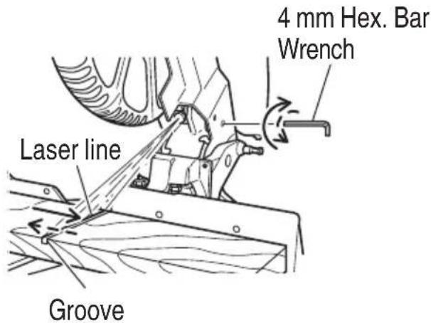
Fig. 10
English
WARNING (Fig. 11 and Fig. 12)
○ Make sure before plugging the power plug into the receptacle that the main body and the laser marker are turned off.
Exercise utmost caution in handling a switch trigger for the position adjustment of the laser line, as the power plug is plugged into the receptacle during operation.
If the switch trigger is pulled inadvertently, the saw blade can rotate and result in unexpected accidents.
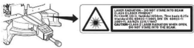
Fig. 11
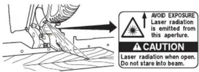
Fig. 12
○ Do not remove the laser marker to be used for other purposes.
CAUTION
○ Laser radiation - Do not stare into beam.
○ Laser radiation on work table. Do not stare into beam. If your eye is exposed directly to the laser beam, it can be hurt.
○ Do not dismantle it.
Do not give strong impact to the laser marker (main body of tool); otherwise, the position of a laser line can go out of order, resulting in the damage of the laser marker as well as a shortened service life.
Keep the laser marker lit only during a cutting operation. Prolonged lighting of the laser marker can result in a shortened service life.
○ Use of controls or adjustments or performance of procedures other than those specified herein may result in hazardous radiation exposure.
NOTE
○ Perform cutting by overlapping the ink line with the laser line.
When the ink line and the laser line are overlapped, the strength and weakness of light will change, resulting in a stable cutting operation because you can easily discern the conformity of lines. This ensures the minimum cutting errors.
☐ In outdoor or near-the-window operations, it may become difficult to observe the laser line due to the sunlight. Under such circumstances, move to a place that is not directly under the sunlight and engage in the operation.
Do not tug on the cord behind the motor head or hook your finger, wood and the like around it; otherwise, the cord may come off and the laser marker may not be lit up.
☐ Check and make sure on a periodic basis if the position of the laser line is in order. As regards the checking method, draw a right-angle ink line on the workpiece with the height of about 38 mm and the width of 89 mm, and check that the laser line is in line with the ink line [The deviation between the ink line and the laser line should be less than the ink line width (0.5 mm)] (Fig. 13).
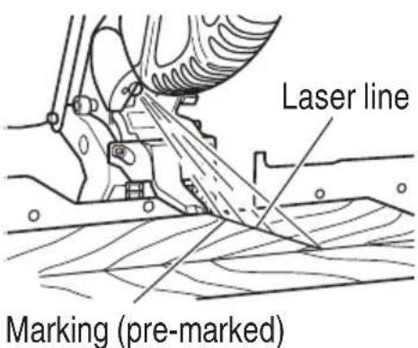
Fig. 13
8. Digital display panel (for C12LCH) (Fig. 14 and Fig. 15)
(1) Turning on the digital display switch shows 0^ for both miter and bevel angle, regardless of main unit angle.
(2) Align the main unit angle with the tilt angle (0°) and miter angle (0°) and hold down their reset buttons for at least 0.2 seconds.
(3) Turning on the laser marker switch while the digital display switch is on, lights up the laser marker (On the C12FCH, only the laser marker switch).
CAUTION
○ When operating the digital panel, have the motor head section at the top limit position and the blade stopped.
If the figure shown on the miter angle digital display is different from the positive stop angle (for example, 45.0^ 45.5^ , 31.6^ 32.0^ )
then the positive stop has probably deviated slightly from its correct position. If this happens, do as follows.
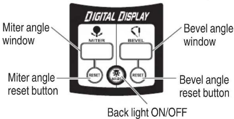
Fig. 14
Switch
(For laser marker)
Switch
(For Digital display)
(Only C12LCH)

natural_image
Technical line drawing of a mechanical component with no visible text or symbolsFig. 15
(1) Move the turntable left and right with the side handle loosened, and set the turntable to the correct position.
(2) If the figures on the display and positive stop still do not match, then return the turntable to the 0^ position. Next move the turntable left and right with the side handle loosened as shown in Fig. 16. After setting it to the correct position 0^ , press the reset button again.
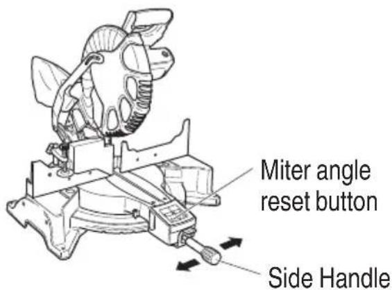
Fig. 16
NOTE
Before starting to cut, align the main unit to the miter angle 0^ and the bevel angle 0^ and hold down the reset buttons for at least
0.2 seconds. If you press the digital display switch to ON without aligning the main unit to 0^ , then the figures appearing on the digital display and the main unit angle will not match.
☐ The laser marker will not light up if the digital display switch is turned off (only on C12LCH).
English
☐ Do not use the main unit near equipment that generates electrical noise such as generators. Electrical noise might cause faulty readings or operation on the digital display.
9. Cutting operation
(1) As shown in Fig. 17 the width of the saw blade is the width of the cut. Therefore, slide the workpiece to the right (viewed from the operator's position) when length ⓑ is desired, or to the left when length ⓐ is desired.
If a laser marker is used, align the laser line with the left side of the saw blade, and then align the ink line with the laser line.
(2) Once the saw blade reaches maximum speed, slowly push down the handle and bring the saw blade in the vicinity of the material to be cut.
(3) Once the saw blade contacts the workpiece, push the handle down gradually to cut into the workpiece.
(4) After cutting the workpiece to the desired depth, turn the power tool OFF and let the saw blade stop completely before raising the handle from the workpiece to return it to the full retract position.
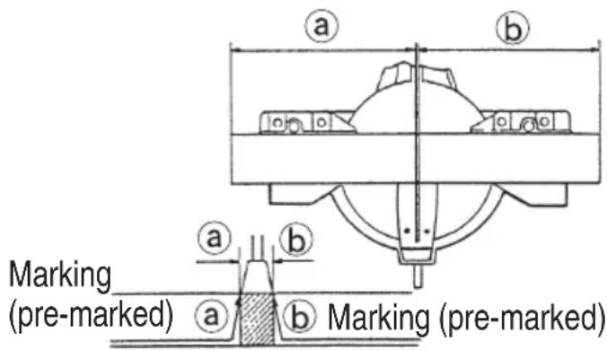
Fig. 17
CAUTION
☐ For maximum dimensions for cutting, refer to “SPECIFICATIONS” table.
○ Increased pressure on the handle will not increase the cutting speed. On the contrary, too much pressure may result in overload of the motor and/or decreased cutting efficiency.
☐ Confirm that the trigger switch is turned OFF and the power plug has been removed from the receptacle whenever the tool is not in use.
Always turn the power off and let the saw blade stop completely before raising the handle from the workpiece. If the handle is raised while the saw blade is still rotating, the cut-off piece may become jammed against the saw blade causing fragments to scatter about dangerously.
Every time one cutting of deep-cutting operation is finished, turn the switch off, and check that the saw blade has stopped. Then raise the handle, and return it to the full retract position.
○ Be absolutely sure to remove the cut material from the top of the turntable, and then proceed to the next step.
- Miter cutting procedures
(1) Loosen the side handle and push the lever for angle stoppers. Then, adjust the turntable until the indicator aligns with desired setting on the miter scale (Fig. 18).
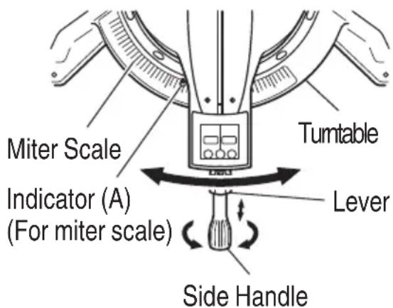
Fig. 18
(2) Re-tighten the side handle to secure the turntable in the desired position.
NOTE
Positive stops are provided at the right and left of the 0^ center setting, at 15^ , 22.5^ , 31.6^ and 45^ settings.
Check that the miter scale and the tip of the indicator are properly aligned.
Operation of the saw with the miter scale and indicator out of alignment, or with the side handle not properly tightened, will result in poor cutting precision.
CAUTION
Never remove the side handle; use of the tool without it would be hazardous. To prevent an accident or personal injury always firmly tighten the miter handle.
- Bevel cutting procedures (Fig. 19)
(1) Loosen the clamp lever and bevel the saw blade to the left.
(2) Adjust the bevel angle to the desired setting while watching the bevel angle scale and indicator, then secure the clamp lever.
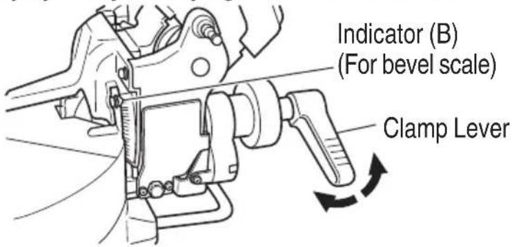
Fig. 19
WARNING
When the workpiece is secured on the left or right side of the blade, the short cut-off portion will come to rest on the right or left side of the saw blade. Always turn the power off and let the saw blade stop completely before raising the handle from the workpiece.
If the handle is raised while the saw blade is still rotating, the cut-off piece may become jammed against the saw blade causing fragments to scatter about dangerously.
When stopping the bevel cutting operation halfway, start cutting after pulling back the motor head to the initial position.
Starting from halfway, without pulling back, causes the lower guard to be caught in the cutting groove of the workpiece and to contact the saw blade.
- Bevel angle fine adjustment (Fig. 20 and Fig. 21)
(1) Grip the handle on the motor head and position it at the bevel angle you need. Temporarily tighten the clamp lever.
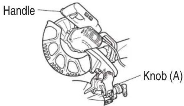
Fig. 20
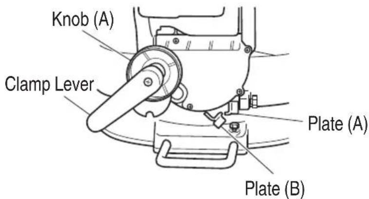
Fig. 21
English
CAUTION
If not tightened firmly enough the motor head might suddenly move or slip, causing injuries. Be sure to tighten the motor head section enough so it will not move.
(2) Make fine adjustments to the bevel angle by gripping the handle and moving the knob (A).
NOTE
Turning knob (A) clockwise, allows fine adjustment of the main unit to the left (as seen from front).
Turning knob (A) counterclockwise, allows fine adjustment of the main unit to the right (as seen from front).
If you tilt the main unit in the direction that does not place a load on plate (A) and pull plate (A), the contact position changes and the right slope angle becomes 3^ .
If you tilt the main unit in the direction that does not place a load on plate (B) and pull plate (B), the contact position changes and the right slope angle becomes 48^ .
(3) After adjusting to the desired angle, tighten the clamp lever and clamp the motor head.
CAUTION
Always check that the clamp lever is secured and the motor head is clamped. If you attempt angle cutting without clamping the motor head, then the motor head might shift unexpectedly causing injuries.
- Compound cutting procedures
Compound cutting can be performed by following the instructions in 10 and 11 above. For maximum dimensions for compound cutting, refer to "SPECIFICATIONS" table.
CAUTION
Always secure the workpiece with the right hand side for compound cutting. Never rotate the table to the right for compound cutting, because the saw blade might then contact the clamp or vise that secures the workpiece, and cause personal injury or damage.
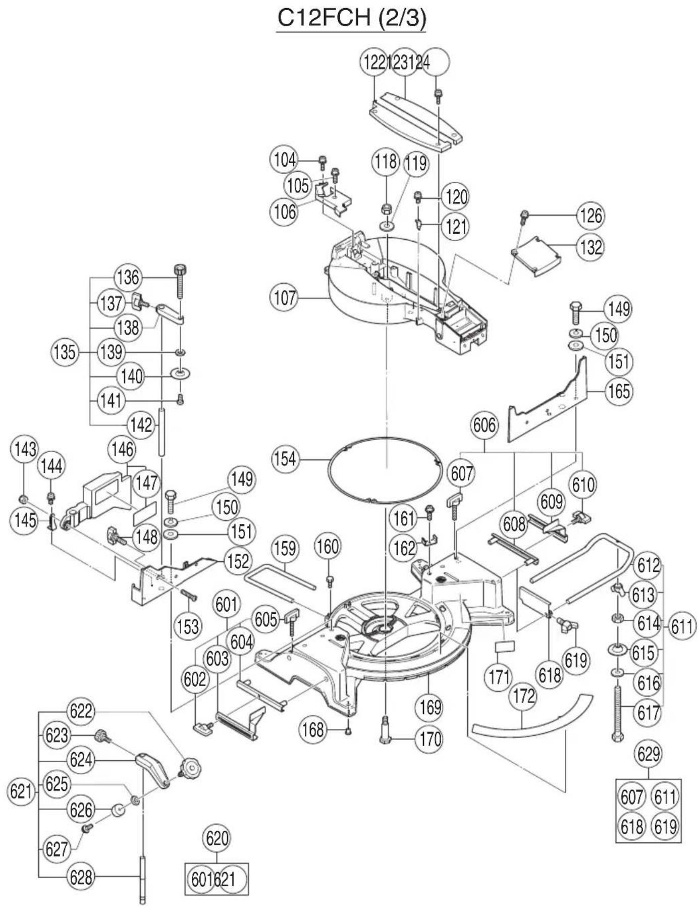
- Installing the holders (Optional accessory)
The holders help keep longer workpieces stable and in place during the cutting operation.
(1) As indicated in Fig. 22, use a steel square for aligning the upper edge of the holders with the base surface.
Loosen the 6 mm wing nut. Turn a height adjustment bolt 6 mm, and adjust the height of the holder.
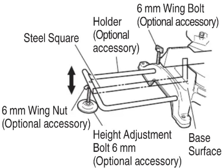
Fig. 22
(2) After adjustment, firmly tighten the wing nut and fasten the holder with the 6 mm knob bolt (optional accessory). If the length of Height Adjustment Bolt 6 mm is insufficient, spread a thin plate beneath. Make sure the end of Height Adjustment Bolt 6 mm does not protrude from the holder.
- Stopper for precision cutting (Stopper and holder are optional accessory)
The stopper facilitates continuous precision cutting in lengths of 280 mm to 450 mm.
To install the stopper, attach it to the holder with the 6 mm wing bolt as shown in Fig. 23.
- Confirmation for use Crown molding vise, Crown molding Stopper (L) and (R) (Optional accessory)
(1) Crown molding Stopper (L) and (R) (optional accessories) allow easier cuts of crown molding without tilting the saw blade. Install them in the base both-sides side to be shown in Fig. 24. After inserting tighten the 6 ~mm knob bolts to secure the Crown molding Stoppers.
Fig. 24
English
(2) The crown molding vise (B) (Optional accessory) can be mounted on either the left fence (Fence (B)) or the right fence (Fence (A)). It can unite with the slope of the crown molding and vice can be pressed down.
Then turn the upper knob, as necessary, to securely attach the crown molding in position. To raise or lower the vise assembly, first loosen the 6 mm wing bolt.
After adjusting the height, firmly tighten the 6 mm wing bolt; then turn the upper knob, as necessary, to securely attach the crown molding in position (See Fig. 25).
Fig. 25
Position crown molding with its WALL CONTACT EDGE against the guide fence and its CEILING CONTACT EDGE against the Crown molding Stoppers as shown in Fig. 25. Adjust the Crown molding Stoppers according to the size of the crown molding.
Tighten the 6 mm wing bolt to secure the Crown molding Stoppers.
WARNING
Always firmly clamp or vise to secure the crown molding to the fence; otherwise the crown molding might be thrust from the table and cause bodily harm.
Do not bevel cutting. The main body or saw blade may contact the sub fence, resulting in an injury.
CAUTION
Always confirm that the motor head (see Fig. 1 on page 38) does not contact the crown molding vise assembly when it is lowered for cutting. If there is any danger that it may do so, loosen the 6 mm knob bolt and move the crown molding vise assembly to a position where it will not contact the saw blade.
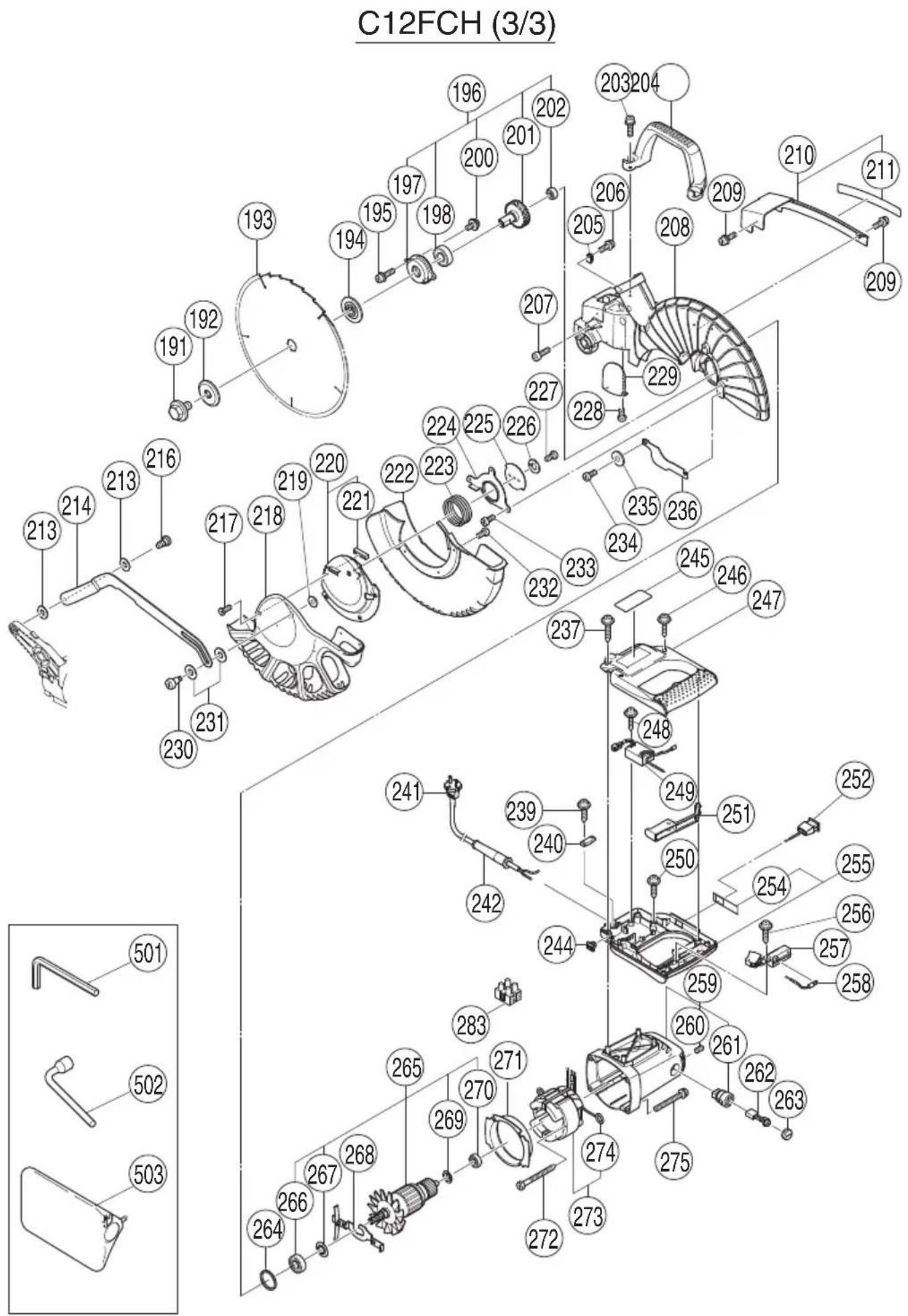
MOUNTING AND DISMOUNTING SAW BLADE
WARNING
To prevent an accident or personal injury, always turn off the trigger switch and disconnect the power plug from the receptacle before removing or installing a blade. If cutting work is done in a state where the bolt is not sufficiently tightened, the bolt can get loose, the blade can come off, and the lower guard can get damaged, resulting in injuries.
Also, check that the bolts are properly tightened before plugging the power plug into the receptacle.
☐ If the bolts are attached or detached using tools other than the 17 mm box wrench (standard accessory), excessive or improperly tightening occurs, resulting in injury.
- Mounting the saw blade (Fig. 26, Fig. 27 and Fig. 28)
(1) Rotate the lower guard (plastic) to the top position.
(2) Press in spindle lock and loosen bolt with 17 mm box wrench (standard accessory).
Since the bolt is left-hand threaded, loosen by turning it to the right as show in Fig. 27.
NOTE
If the spindle lock cannot be easily pressed in to lock the spindle, turn the bolt with 17 mm box wrench (standard accessory) while applying pressure on the spindle lock.
The saw blade spindle is locked when the spindle lock is pressed inward.
(4) Remove the bolt and washer (B).
(5) Lift the lower guard and mount the saw blade.
WARNING
When mounting the saw blade, confi rm that the rotation indicator mark on the saw blade and the rotation direction of the gear case (see Fig. 1 on page 38) are properly matched.
(6) Thoroughly clean washer (B) and the bolt, and install them onto the saw blade spindle.
(7) Press in the spindle lock and tighten the bolt by turning it to the left by standard accessories wrench (17 mm box wrench) as indicated in Fig. 27.
Spindle Lock

natural_image
Line drawing of a mechanical device with no visible text or symbolsFig. 26
Fig. 27
Fig. 28
CAUTION
○ Confirm that the spindle lock has returned to the retract position after installing or removing the saw blade.
○ Tighten the bolt so it does not come loose during operation.
○ Confirm that the bolt has been properly tightened before the power tool is started.
2. Dismounting the saw blade
Dismount the saw blade by reversing the mounting procedures described in paragraph 1 above. The saw blade can easily be removed after lifting the lower guard.
MAINTENANCE AND INSPECTION
WARNING
To avoid an accident or personal injury, always confirm the trigger switch is turned OFF and that the power plug has been disconnected from the receptacle before performing any maintenance or inspection of this tool.
- Inspecting the saw blade
Always replace the saw blade immediately upon the first sign of deterioration or damage. A damaged saw blade can cause personal injury and a worn saw blade can cause ineffic active operation and possible overload to the motor.
CAUTION
Never use a dull saw blade. When a saw blade is dull, its resistance to the hand pressure applied by the tool handle tends to increase, making it unsafe to operate the power tool.
- Inspecting the lever (Fig. 29 and Fig. 30)
If the M8 hexagonal head bolts (2) are loose, align the sides of the fence and saw blade with the steel square. After adjusting the saw blade and fence to a ninety-degree angle, tighten the lever securing hexagonal head bolts (2).
- Inspecting the carbon brushes (Fig. 31 and Fig. 32)
The carbon brushes in the motor are expendable parts.
If the carbon brushes become excessively worn, motor trouble might occur.
Therefore, inspect the carbon brushes periodically and replace them when they have become worn to the wear limit line as shown in Fig. 31.
Also, keep the carbon brushes clean so that they will slide smoothly within the brush holders.
The carbon brushes can easily be removed after removal of the brush caps (see Fig. 32) with a slotted (minus) screwdriver.
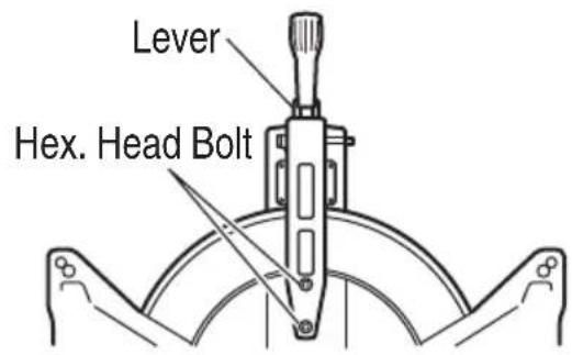
Fig. 29
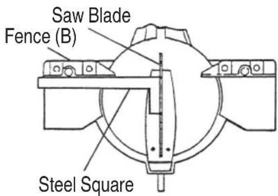
Fig. 30
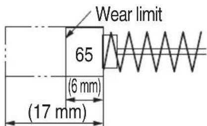
Fig. 31

Fig. 32
4. About Handling the Motor (see Fig. 1 on page 38)
Winding of the motor is said to be the heart of this tool. Exercise utmost caution not to damage the winding by exposing it to wash oil or water.
NOTE
Accumulation of dust and the like inside the motor can result in a malfunction.
After using the motor for 50 hours or so, carry out no-load running, and blow in the dry air from a wind hole at the motor's rear. Such action is effective to discharge dust and the like.
5. Inspecting the screws
Regularly inspect each component of the power tool for looseness.
Re-tighten screws on any loose part.
WARNING
To prevent personal injury, never operate the power tool if any components are loose.
6. Inspecting the lower guard for proper operation
Before each use of the tool, test the lower guard (see Fig. 1 on page 38) to assure that it is in good condition and that it moves smoothly.
Never use the tool unless the lower guard operates properly and it is in good mechanical condition.
7. Storage
After operation of the tool has been completed, check that the following has been performed:
(1) Trigger switch is in OFF position,
(2) Power plug has been removed from the receptacle,
When the tool is not in use, keep it stored in a dry place out of the reach of children.
8. Lubrication
Lubricate the following sliding surfaces once a month to keep the power tool in good operating condition for a long time (Fig. 1 on page 38 and Fig. 2 on page 38).
Use of machine oil is recommended.
Oil supply points:
* Rotary portion of hinge
* Rotary portion of vise assembly
9. Cleaning
Periodically remove chips, dust and other waste material from the surface of the power tool, especially from the inside of the lower guard with a damp, soapy cloth. To avoid a malfunction of the motor, protect it from contact with oil or water.
If the laser line becomes invisible due to chips and the like adhered onto the window of the laser marker's light-emitting section, wipe and clean the window with a dry cloth or a soft cloth moistened with soapy water, etc.
English
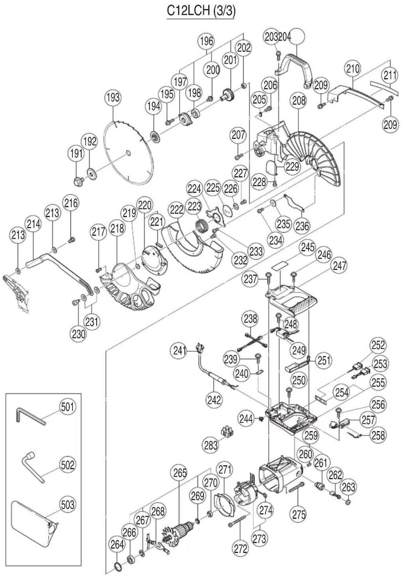
10. Service parts list
CAUTION
Repair, modification and inspection of HiKOKI Power Tools must be carried out by a HiKOKI Authorized Service Center.
Especially laser device should be maintained by the authorised agent by laser manufacturer.
Always assign the repair of laser device to HiKOKI Authorised Service Center.
This Parts List will be helpful if presented with the tool to the HiKOKI Authorized Service Center when requesting repair or other maintenance.
In the operation and maintenance of power tools, the safety regulations and standards prescribed in each country must be observed.
SERVICE PARTS LIST

English
| Item No. | Code No. | No. Used | Remarks |
| 1 | 323-141 | 1 | |
| 2 | 323-137 | 1 | |
| 3 | 323-138 | 1 | |
| 4 | 949-900 | 1 D3 × 14 | |
| 5 | 323-142 | 2 | |
| 6 | 962-782 | 1 M5 × 6 | |
| 7 | 949-531 | 1 D2 × 12 | |
| 8 | 323-144 | 1 M5 | |
| 9 | 975-144 | 1 | |
| 10 | 323-139 | 1 “11” | |
| 11 | 1 | ||
| 12 | 323-647 | 1 | |
| 13 | 323-143 | 2 | |
| 14 | 323-140 | 1 | |
| 15 | 323-136 | 1 | |
| 16 | 323-208 | 1 M6 × 20 | |
| 17 | 322-935 | 1 | |
| 18 | 323-665 | 1 M10 | |
| 19 | 323-666 | 1 | |
| 20 | 323-597 | 1 | |
| 21 | 304-043 | 1 M4 × 10 | |
| 22 | 323-598 | 1 | |
| 23 | 323-599 | 1 | |
| 24 | 949-821 | 1 M5 × 16 | |
| 25 | 949-454 | 1 | |
| 26 | 323-596 | 1 | |
| 27 | 322-933 | 1 | |
| 28 | 322-934 | 1 M16 | |
| 29 | 323-593 | 1 | |
| 30 | 323-663 | 1 | |
| 31 | 993-539 | 1 M4 × 16 | |
| 32 | 980-523 | 1 | |
| 33 | 323-600 | 1 | |
| 34 | 949-241 | 1 M5 × 20 | |
| 35 | 949-432 | 1 M6 | |
| 36 | 323-142 | 2 | |
| 37 | 323-619 | 1 | |
| 38 | 949-216 | 4 M4 × 10 | |
| 39 | 307-956 | 1 M6 × 10 | |
| 40 | 323-594 | 1 |
| Item No. | Code No. | No. Used | Remarks |
| 41 | 323-595 | 1 | |
| 42 | 323-684 | 1 | |
| 43 | 302-518 | 1 “44” | |
| 44 | 984-528 | 1 P-6 | |
| 45 | 323-601 | 1 “47-49” | |
| 46 | 990-541 | 2 M5 × 16 | |
| 47 | 323-602 | 1 | |
| 48 | 322-963 | 1 | |
| 49 | 949-214 | 1 M4 × 6 | |
| 50 | 949-431 | 1 M5 | |
| 51 | 949-454 | 1 M5 | |
| 52 | 949-821 | 1 M5 × 16 | |
| 53 | 323-664 | 1 “54” | |
| 54 | 949-900 | 1 D3 × 14 | |
| 55 | 949-660 | 2 M6 × 20 | |
| 56 | 323-683 | 1 | |
| 57 | 949-221 | 2 M4 × 20 | |
| 58 | 949-423 | 2 M4 | |
| 59 | 323-142 | 2 | |
| 60 | 303-006 | 2 D4 × 10 | |
| 61 | 949-432 | 2 M6 | |
| 62 | 323-662 | 1 | |
| 63 | 323-661 | 1 | |
| 64 | 323-659 | 1 | |
| 65 | 303-409 | 2 M8 × 25 | |
| 66 | 935-196 | 2 M4 × 12 | |
| 67 | 322-893 | 1 | |
| 68 | 304-043 | 1 M4 × 10 | |
| 69 | 680-418 | 1 M12 | |
| 70 | 949-217 | 2 M4 × 12 | |
| 71 | 949-423 | 2 M4 | |
| 72 | 323-607 | 1 | |
| 74 | 323-627 | 1 | |
| 75 | 949-457 | 2 M8 | |
| 76 | 949-655 | 2 M8 × 16 | |
| 77 | 323-609 | 1 | |
| 78 | 307-635 | 2 M4 × 10 | |
| 79 | 323-680 | 1 | |
| 80 | 323-646 | 1 “1-10,12-15” |

English
| Item No. | Code No. | No. Used | Remarks | Item No. | Code No. | No. Used | Remarks |
| 101 | 323-658 | 1 380MM | 141 | 949-216 | 1 M4 × 10 | ||
| 102 | 993-539 | 1 M4 × 16 | 142 | 322-954 | 1 | ||
| 103 | 973-313 | 1 | 143 | 311-144 | 1 M6 | ||
| 104 | 304-043 | 1 M4 × 10 | 144 | 304-043 | 1 M4 × 10 | ||
| 105 | 993-539 | 1 M4 × 16 | 145 | 323-631 | 1 | ||
| 106 | 323-650 | 1 | 146 | 323-630 | 1 “147” | ||
| 107 | 323-624 | 1 | 147——— | 1 | |||
| 108 | 323-142 | 2 | 148 | 301-806 | 1 M6 × 15 | ||
| 109 | 323-619 | 1 | 149 | 949-678 | 4 M8 × 35 | ||
| 110 | 323-622 | 1 | 150 | 949-457 | 4 M8 | ||
| 111 | 949-432 | 1 M6 | 151 | 949-433 | 4 M8 | ||
| 112 | 949-241 | 1 M5 × 20 | 152 | 323-629 | 1 | ||
| 113 | 975-144 | 1 | 153 | 323-685 | 1 M6 × 30 | ||
| 114 | 323-621 | 1 | 154 | 323-625 | 3 | ||
| 115 | 993-539 | 1 M4 × 16 | 155 | 302-317 | 2 M5 × 16 | ||
| 116 | 323-617 | 1 | 156 | 949-431 | 2 M5 | ||
| 117 | 323-620 | 1 160MM | 157 | 323-604 | 1 | ||
| 118 | 975-348 | 1 M8 | 158 | 323-603 | 1 | ||
| 119 | 318-929 | 1 | 159 | 322-910 | 1 | ||
| 120 | 304-043 | 1 M4 × 10 | 160 | 949-610 | 1 M6 × 10 | ||
| 121 | 318-927 | 1 | 161 | 987-512 | 1 M5 × 16 | ||
| 122 | 323-648 | 1 | 162 | 323-605 | 1 | ||
| 123 | 323-649 | 1 | 163 | 323-623 | 1 | ||
| 124 | 990-541 | 4 M5 × 16 | 164 | 949-215 | 1 M4X × 8 | ||
| 125 | 323-612 | 1 | 165 | 323-628 | 1 | ||
| 126 | 993-539 | 4 M4 × 16 | 168 | 323-606 | 4 | ||
| 127 | 323-616 | 1 | 169———“168,171,172” | ||||
| 128 | 323-615 | 1 “127” | 170 | 323-626 | 1 | ||
| 129 | 323-608 | 1 | 171——— | 1 | |||
| 130 | 321-672 | 10 D2 × 6 | 172 | 323-656 | 1 | ||
| 131 | 323-613 | 1 | 173 | 323-610 | 1 “125,130-133” | ||
| 132 | 323-611 | 1 | 601 | 323-546 | 1 “602-605” | ||
| 133 | 323-614 | 1 | 602 | 301-806 | 1 M6 × 15 | ||
| 134 | 323-618 | 1 | 603——— | 1 | |||
| 135 | 323-677 | 1 “136-142” | 604 | 321-390 | 1 | ||
| 136 | 323-678 | 1 | 605 | 323-682 | 1 M6 × 85 | ||
| 137 | 301-806 | 1 M6 × 15 | 606 | 323-547 | 1 “607-610” | ||
| 138——— | 1 | 607 | 323-682 | 2 M6 × 85 | |||
| 139 | 949-432 | 1 M6 | 608 | 321-390 | 1 | ||
| 140 | 302-532 | 1 | 609——— | 1 | |||
| Item No. | Code No. | No. Used | Remarks |
610 301-806 1 M6 × 15
611 323-657 1 "612-617"
612 321-549 1
613 949-313 1 M6
614 949-556 1 M6
615 322-047 1
616 949-425 1 M6
617 323-681 1 M6 × 105
618 974-561 1
619 949-404 1 M6X × 20
620 323-545 1 "601,621"
621 322-957 1 "622-628"
622 321-551 1 M10 × 54
623 998-836 1 M6 × 11
624—1
625 306-985 1
626 964-851 1
627 304-043 1 M4 × 10
628 318-967 1
629 323-523 1 "607,611,618,619"
English
| Item No. | Code No. | No. Used | Remarks |
| 191 | 988-101 | 1 M10 | |
| 192 | 323-652 | 1 | |
| 193 | 305MM-D25.4-NT120 | ||
| 194 | 323-651 | 1 | |
| 195 | 323-208 | 2 M6 × 20 | |
| 196 | 323-639 | 1 “197,198,200-202” | |
| 197 | 323-641 | 1 | |
| 198 | 320-3VV | 1 6203VVCMPS2L | |
| 200 | 304-043 | 2 M4 × 10 | |
| 201 | 323-640 | 1 | |
| 202 | 608-VVM | 1 608VVC2PS2L | |
| 203 | 323-208 | 2 M6 × 20 | |
| 204 | 322-924 | 1 | |
| 205 | 980-523 | 1 | |
| 206 | 935-196 | 1 M4 × 12 | |
| 207 | 949-755 | 1 M6 × 16 | |
| 208 | 323-638 | 1 | |
| 209 | 993-539 | 2 M4 × 16 | |
| 210 | 323-653 | 1 “211” | |
| 211 | 323-654 | 1 | |
| 213 | 322-948 | 2 M7 | |
| 214 | 323-674 | 1 | |
| 216 | 322-950 | 1 M6 | |
| 217 | 318-363 | 1 M4 × 10 | |
| 218 | 323-668 | 1 | |
| 219 | 949-454 | 1 M5 | |
| 220 | 323-672 | 1 “221” | |
| 221 | 323-673 | 1 | |
| 222 | 323-667 | 1 | |
| 223 | 323-671 | 1 | |
| 224 | 323-669 | 1 | |
| 225 | 323-670 | 1 | |
| 226 | 949-454 | 1 M5 | |
| 227 | 949-236 | 1 M5 × 10 | |
| 228 | 949-216 | 1 M4 × 10 | |
| 229 | 322-926 | 1 | |
| 230 | 322-947 | 1 M5 | |
| 231 | 322-938 | 2 M10 | |
| 232 | 949-215 | 3 M4 × 8 | |
| 233 | 323-040 | 3 M5 × 10 | |
| 234 | 323-040 | 2 M5 × 10 | |
| 235 | 949-431 | 1 M5 | |
| 236 | 323-675 | 1 |
| Item No. | Code No. | No. Used | Remarks |
| 237 | 307-028 | 2 D4 × 25 | |
| 238 | 323-632 | 1 | |
| 239 | 984-750 | 2 D4 × 16 | |
| 240 | 937-631 | 1 | |
| 241 | 1 | ||
| 242 | 940-778 | 1 D10.7 | |
| 244 | 319-349 | 1 | |
| 245 | 1 | ||
| 246 | 301-653 | 4 D4 × 20 | |
| 247 | 323-642 | 1 | |
| 248 | 984-750 | 1 D4 × 16 | |
| 249 | 322-911 | 1 | |
| 250 | 301-653 | 2 D4 × 20 | |
| 251 | 323-645 | 1 | |
| 252 | 323-634 | 1 | |
| 253 | 323-635 | 1 | |
| 254 | 323-644 | 1 | |
| 255 | 323-643 | 1 “254” | |
| 256 | 984-750 | 1 D4 × 16 | |
| 257 | 320-950 | 1 | |
| 258 | 323-633 | 1 | |
| 259 | 322-914 | 1 “260,261” | |
| 260 | 938-477 | 2 M5 × 8 | |
| 261 | 938-241 | 2 | |
| 262 | 999-065 | 2 | |
| 263 | 945-161 | 2 | |
| 264 | 303-792 | 1 | |
| 265 | 1 “266,267,269,270” | ||
| 266 | 620-2VV | 1 6202VVCMPS2L | |
| 267 | 980-700 | 1 | |
| 268 | 323-637 | 1 | |
| 269 | 302-428 | 1 | |
| 270 | 600-0VV | 1 6000VVCMPS2L | |
| 271 | 322-915 | 1 | |
| 272 | 953-174 | 2 D5 × 55 | |
| 273 | 1 “274” | ||
| 274 | 937-623 | 2 | |
| 275 | 322-123 | 4 M5 × 40 | |
| 283 | 958-308Z | 1 | |
| 501 | 944-458 | 1 4MM | |
| 502 | 985-051 | 1 17MM | |
| 503 | 322-955 | 1 |
C12FCH (1/3)
| Item No. | Code No. | No. Used | Remarks |
| 1 | 323-141 1 | ||
| 2 | 323-137 1 | ||
| 3 | 323-138 1 | ||
| 4 | 949-900 1 | D3 × 14 | |
| 5 | 323-142 2 | ||
| 6 | 962-782 1 | M5 × 6 | |
| 7 | 949-531 1 | D2 × 12 | |
| 8 | 323-144 1 | M5 | |
| 9 | 975-144 1 | ||
| 10 | 323-139 1 | "11" | |
| 11 | 1 | ||
| 12 | 323-647 1 | ||
| 13 | 323-143 2 | ||
| 14 | 323-140 1 | ||
| 15 | 323-136 1 | ||
| 16 | 323-208 1 | M6 × 20 | |
| 17 | 322-935 1 | ||
| 18 | 323-665 1 | M10 | |
| 19 | 323-666 1 | ||
| 20 | 323-597 1 | ||
| 21 | 304-043 1 | M4 × 10 | |
| 22 | 323-598 1 | ||
| 23 | 323-599 1 | ||
| 24 | 949-821 1 | M5 × 16 | |
| 25 | 949-454 1 | ||
| 26 | 323-596 1 | ||
| 27 | 322-933 1 | ||
| 28 | 322-934 1 | M16 | |
| 29 | 323-593 1 | ||
| 30 | 323-663 1 | ||
| 39 | 307-956 1 | M6 × 10 | |
| 40 | 323-594 1 | ||
| 41 | 323-595 1 | ||
| 42 | 323-684 1 | ||
| 43 | 302-518 1 | "44" | |
| 44 | 984-528 1 | P-6 | |
| 45 | 323-719 1 | "47-49" | |
| 46 | 990-541 2 | M5 × 16 | |
| 47 | 323-697 1 | ||
| 48 | 322-963 1 |
| Item No. | Code No. | No. Used | Remarks |
| 49 | 949-214 | 1 M4 × 6 | |
| 50 | 949-431 | 1 M5 | |
| 51 | 949-454 | 1 M5 | |
| 52 | 949-821 | 1 M5 × 16 | |
| 53 | 323-664 | 1 “54” | |
| 54 | 949-900 | 1 D3 × 14 | |
| 55 | 949-660 | 2 M6 × 20 | |
| 56 | 323-683 | 1 | |
| 57 | 949-221 | 2 M4 × 20 | |
| 58 | 949-423 | 2 M4 | |
| 59 | 323-142 | 2 | |
| 60 | 303-006 | 2 D4 × 10 | |
| 61 | 949-432 | 2 M6 | |
| 62 | 323-662 | 1 | |
| 63 | 323-661 | 1 | |
| 64 | 323-659 | 1 | |
| 65 | 303-409 | 2 M8 × 25 | |
| 66 | 935-196 | 2 M4 × 12 | |
| 67 | 322-893 | 1 | |
| 68 | 304-043 | 1 M4 × 10 | |
| 69 | 680-418 | 1 M12 | |
| 74 | 323-627 | 1 | |
| 75 | 949-457 | 2 M8 | |
| 76 | 949-655 | 2 M8 × 16 | |
| 77 | 323-609 | 1 | |
| 78 | 307-635 | 2 M4 × 10 | |
| 79 | 323-680 | 1 | |
| 80 | 323-646 | 1 “1-10,12-15” |
English

| Item No. | Code No. | No. Used | Remarks |
| 104 | 949-216 | 1 M4 × 10 | |
| 105 | 954-878 | 1 M4 × 16 | |
| 106 | 323-650 | 1 | |
| 107 | 323-624 | 1 | |
| 118 | 975-348 | 1 M8 | |
| 119 | 318-929 | 1 | |
| 120 | 304-043 | 1 M4 × 10 | |
| 121 | 318-927 | 1 | |
| 122 | 323-648 | 1 | |
| 123 | 323-649 | 1 | |
| 124 | 990-541 | 4 M5 × 16 | |
| 126 | 993-539 | 4 M4 × 16 | |
| 132 | 323-693 | 1 | |
| 135 | 323-677 | 1 “136-142” | |
| 136 | 323-678 | 1 | |
| 137 | 301-806 | 1 M6 × 15 | |
| 138 | 1 | ||
| 139 | 949-432 | 1 M6 | |
| 140 | 302-532 | 1 | |
| 141 | 949-216 | 1 M4 × 10 | |
| 142 | 322-954 | 1 | |
| 143 | 311-144 | 1 M6 | |
| 144 | 304-043 | 1 M4 × 10 | |
| 145 | 323-631 | 1 | |
| 146 | 323-630 | 1 “147” | |
| 147 | 1 | ||
| 148 | 301-806 | 1 M6 × 15 | |
| 149 | 949-678 | 4 M8 × 35 | |
| 150 | 949-457 | 4 M8 | |
| 151 | 949-433 | 4 M8 | |
| 152 | 323-629 | 1 | |
| 153 | 323-685 | 1 M6 × 30 | |
| 154 | 323-625 | 3 | |
| 159 | 322-910 | 1 | |
| 160 | 949-610 | 1 M6 × 10 | |
| 161 | 987-512 | 1 M5 × 16 | |
| 162 | 323-605 | 1 | |
| 165 | 323-628 | 1 | |
| 168 | 323-606 | 4 | |
| 169 | 1 “168,171,172” |
| Item No. | Code No. | No. Used | Remarks |
| 170 | 323-626 | 1 | |
| 171 | 1 | ||
| 172 | 323-692 | 1 | |
| 601 | 323-546 | 1 “602-605” | |
| 602 | 301-806 | 1 M6 × 15 | |
| 603 | 1 | ||
| 604 | 321-390 | 1 | |
| 605 | 323-682 | 1 M6 × 85 | |
| 606 | 323-547 | 1 “607-610” | |
| 607 | 323-682 | 2 M6 × 85 | |
| 608 | 321-390 | 1 | |
| 609 | 1 | ||
| 610 | 301-806 | 1 M6 × 15 | |
| 611 | 323-657 | 1 “612-617” | |
| 612 | 321-549 | 1 | |
| 613 | 949-313 | 1 M6 | |
| 614 | 949-556 | 1 M6 | |
| 615 | 322-047 | 1 | |
| 616 | 949-425 | 1 M6 | |
| 617 | 323-681 | 1 M6 × 105 | |
| 618 | 974-561 | 1 | |
| 619 | 949-404 | 1 M6X × 20 | |
| 620 | 323-545 | 1 “601,621” | |
| 621 | 322-957 | 1 “622-628” | |
| 622 | 321-551 | 1 M10 × 54 | |
| 623 | 998-836 | 1 M6 × 11 | |
| 624 | 1 | ||
| 625 | 306-985 | 1 | |
| 626 | 964-851 | 1 | |
| 627 | 304-043 | 1 M4 × 10 | |
| 628 | 318-967 | 1 | |
| 629 | 323-523 | 1 “607,611,618,619” |
English
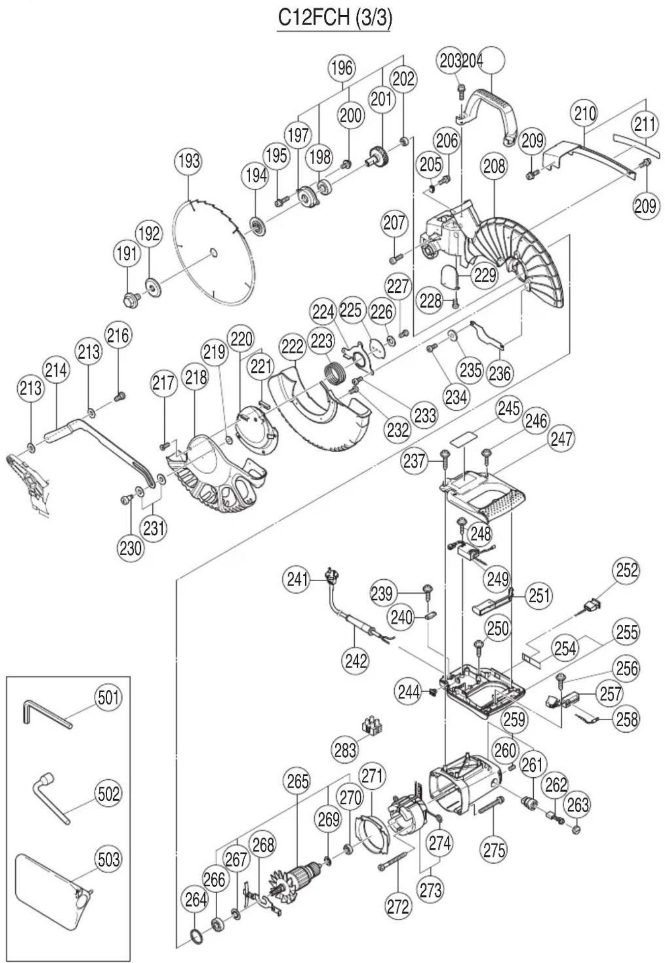
Item No. Code No. No. Remarks Used
191988-1011M10
192323-6521
193 305MM-D25.4-NT120
194323-6511
195 323-208 2 M6 × 20
196323-6391"197,198,200-202"
197323-6411
198620-3VV16203VVCMPS2L
200 304-043 2 M4 × 10
201323-6401
202608-VVM1608VVC2PS2L
203 323-208 2 M6 × 20
204322-9241
205980-5231
206 935-196 1 M4 × 12
207 949-755 1 M6 × 16
208323-6381
209 993-539 2 M4 × 16
210323-6531"211"
211323-6541
213322-9482M7
214323-6741
216322-9501M6
217 318-363 1 M4 × 10
218323-6981
219949-4541M5
220323-6721"221"
221323-6731
222323-6671
223323-6711
224323-6691
225323-6701
226949-4541M5
227 949-236 1 M5 × 10
228 304-043 1 M4 × 10
229322-9261
230322-9471M5
231322-9382M10
232 949-215 3 M4 × 8
233 323-040 3 M5 × 10
234 323-040 2 M5 × 10
235949-4311M5
Item No. Code No. No. Remarks Used
236323-6751
237 307-028 2 D4 × 25
239 984-750 2 D4 × 16
240937-6311
241 1
242940-7781D10.7
244319-3491
245 1
246 301-653 4 D4 × 20
247323-6421
248 984-750 1 D4 × 16
249322-9111
250 301-653 2 D4 × 20
251323-6451
252323-6341
254323-6951
255323-6941"254"
256 984-750 1 D4 × 16
257320-9501
258323-6331
259322-9141"260,261"
260 938-477 2 M5 × 8
261938-2412
262999-0652
263945-1612
264303-7921
265——1“266,267,269,270”
266620-2VV16202VVC MPS2L
267980-7001
268323-6371
269302-4281
270600-0VV16000VVCMPS2L
271322-9151
272 953-174 2 D5 × 55
273——1“274”
274937-6232
275 322-123 4 M5 × 40
283958-308Z1
501944-45814MM
502985-051117MM
503322-9551
服务中心
工机商业(中国)有限公司
上海市闵行区浦江工业园区三鲁路3585号7幢3楼
制造商
福建高壹工机有限公司
福建省福州市福兴投资区湖塘路
Koki Holdings Co., Ltd.
806
编号:C99132724 F
发行日期:2018年6月
中国印刷