BELLE PCX 13/40E+ - Vibratory plate ALTRAD - Free user manual and instructions
Find the device manual for free BELLE PCX 13/40E+ ALTRAD in PDF.
User questions about BELLE PCX 13/40E+ ALTRAD
0 question about this device. Answer the ones you know or ask your own.
Ask a new question about this device
Download the instructions for your Vibratory plate in PDF format for free! Find your manual BELLE PCX 13/40E+ - ALTRAD and take your electronic device back in hand. On this page are published all the documents necessary for the use of your device. BELLE PCX 13/40E+ by ALTRAD.
USER MANUAL BELLE PCX 13/40E+ ALTRAD
natural_image
Technical line drawing of a mechanical lawn mower assembly (no text or symbols)GB Operators Manual
F Manuel De L'Opérateur
E Manual del Operador
D Bedienungshandbuch
PL Instrukcja Obstugi
8
32
56
80
104
2
UKCA Declaration of Conformity
3-7
EC/EU Declaration of Conformity
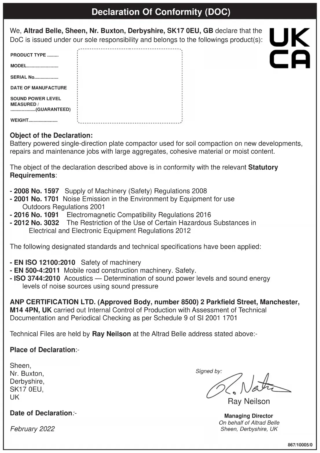
Declaration Of Conformity (DOC)
We, Altrad Belle, Sheen, Nr. Buxton, Derbyshire, SK17 0EU, GB declare that the DoC is issued under our sole responsibility and belongs to the followings product(s):
UK CA
PRODUCT TYPE ......
MODEL......
SERIAL No......
DATE OF MANUFACTURE
SOUND POWER LEVEL MEASURED / ........(GUARANTEED)
WEIGHT......
Object of the Declaration:
Battery powered single-direction plate compactor used for soil compaction on new developments, repairs and maintenance jobs with large aggregates, cohesive material or moist content.
The object of the declaration described above is in conformity with the relevant Statutory Requirements:
- 2008 No. 1597 Supply of Machinery (Safety) Regulations 2008
- 2001 No. 1701 Noise Emission in the Environment by Equipment for use Outdoors Regulations 2001
- 2016 No. 1091 Electromagnetic Compatibility Regulations 2016
- 2012 No. 3032 The Restriction of the Use of Certain Hazardous Substances in Electrical and Electronic Equipment Regulations 2012
The following designated standards and technical specifications have been applied:
- EN ISO 12100:2010 Safety of machinery
- EN 500-4:2011 Mobile road construction machinery. Safety.
- ISO 3744:2010 Acoustics — Determination of sound power levels and sound energy levels of noise sources using sound pressure
ANP CERTIFICATION LTD. (Approved Body, number 8500) 2 Parkfield Street, Manchester, M14 4PN, UK carried out Internal Control of Production with Assessment of Technical Documentation and Periodical Checking as per Schedule 9 of SI 2001 1701
Technical Files are held by Ray Neilson at the Altrad Belle address stated above:-
Place of Declaration:-
Sheen,
Nr. Buxton,
Derbyshire,
SK17 0EU,
UK
Date of Declaration:-
February 2022
Signed by:

text_image
Dr. Nath Ray NeilsonManaging Director
On behalf of Altrad Belle
Sheen, Derbyshire, UK
We, Altrad Belle, Sheen, Nr. Buxton, Derbyshire, SK17 0EU, GB declare that the DoC is issued under our sole responsibility and belongs to the followings product(s):
CE
PRODUCT TYPE ....
MODEL......
SERIAL No......
DATE OF MANUFACTURE .....
SOUND POWER LEVEL MEASURED / ........(GUARANTEED)
WEIGHT......
Signed by:

Ray Neilson
Managing Director
On behalf of Altrad Belle, Sheen, Derbyshire, UK
Place of Declaration:-
Sheen, Nr. Buxton, Derbyshire, SK17 0EU, UK
Date of Declaration:-
February 2022
Object of the Declaration:
Battery powered single-direction plate compactor used for soil compaction on new developments, repairs and maintenance jobs with large aggregates, cohesive material or moist content.
The object of the declaration described above is in conformity with the relevant Union Harmonisation Legislation:
- 2006/42/EC - New machinery directive
- 2000/14/EC - Noise - equipment for use outdoors
The following harmonised standards and technical specifications have been applied:
- EN ISO 12100:2010 Safety of machinery
- EN 500-4:2011 Mobile road construction machinery. Safety.
- ISO 3744:2010 Acoustics — Determination of sound power levels and sound energy levels of noise sources using sound pressure
VINÇOTTE nv/sa (NB0026) carried out Internal Control of Production with Assessment of Technical Documentation and Periodical Checking as per Annex VI of 2000/14/EC
Technical Files are held by Hugues Menager at the following address: Altrad (Group Holding), 125 Rue du Mas Carbonnier, 34000, Montpellier, France.
GBGB
EU Declaration Of Conformity (DOC)
We, Altrad Belle, Sheen, Nr. Buxton, Derbyshire, SK17 0EU, GB declare that the DoC is issued under our sole responsibility and belongs to the followings product(s):
O
PRODUCT TYPE ....
MODEL......
SERIAL No......
DATE OF MANUFACTURE .....
SOUND POWER LEVEL MEASURED / ......(GUARANTEED)
WEIGHT......
See information on sticker above
Signed by:

Ray Neilson
Managing Director
On behalf of Altrad Belle, Sheen, Derbyshire, UK
Place of Declaration:-
Sheen, Nr. Buxton, Derbyshire, SK17 0EU, UK
Date of Declaration:
February 2022
Object of the Declaration:
Battery powered single-direction plate compactor used for soil compaction on new developments, repairs and maintenance jobs with large aggregates, cohesive material or moist content.
The object of the declaration described above is in conformity with the relevant Union Harmonisation Legislation:
- 2014/30/EU - EMC Directive
- 2011/65/EU - Restriction of Hazardous Substances Directive
The following harmonised standards and technical specifications have been applied:
- EN ISO 12100:2010 Safety of machinery
- EN 500-4:2011 Mobile road construction machinery. Safety.
- ISO 3744:2010 Acoustics — Determination of sound power levels and sound energy levels of noise sources using sound pressure
VINÇOTTE nv/sa (NB0026) carried out Internal Control of Production with Assessment of Technical Documentation and Periodical Checking as per Annex VI of 2000/14/EC
Technical Files are held by Hugues Menager at the following address:-
Altrad (Group Holding), 125 Rue du Mas Carbonnier, 34000, Montpellier, France.
- 2006/42/EC - Directive relative aux machines
Ray Neilson Director Genera
UKCA DECLARATION OF CONFORMITY 2
EC/EU DECLARATION OF CONFORMITY 3
INTRODUCTION....9
WARNING 9
Serial Numbers....10
MACHINE DESCRIPTION
General....11
Standard Operation....11
Danger Zone 11
Main Components Locations....12
Power Unit Components 13
Battery Pack Components....13
Battery Charger 14
TECHNICAL DATA
Static Dimensions....15
General Data....16
Battery Pack Data 16
SAFETY INSTRUCTIONS
General....17
Pre-Start Checks....17
Worksites....17
Operating the Machine....17
Battery Charger 18
Battery Pack....19
Weather Conditions....19
During Maintenance....19
After Maintenance....19
Modifications & Replacement Parts 19
Safety Decals 20 - 21
OPERATING INSTRUCTIONS
Reasons for Compaction....22
Applications....22
Charging the Battery Pack 23
Attaching the Battery Pack....23
Stopping the Power Unit....23
Starting the Power Unit 23
Removing the Battery Pack....23
Check the Charge Level of the Battery Pack 24
Transportation 24
Operating the Machine 24
STORAGE....25
SERVICE AND MAINTENANCE
General....26
Maintenance Schedule 26
Drive Belt 27
Vibrator Unit 27
Cleaning 27
TROUBLESHOOTING GUIDE
Power Unit & Operation....28
Battery Back 29
Battery Charger 29
ENVIRONMENT 30
REPLACEMENT PARTS 30
WARRANTY....31
Introduction
The purpose of this publication is to enable the owner/operator to maintain and use the machine efficiently. If these instructions are followed carefully they will contribute to years of efficient and profitable operation of the machines in the true Altrad Belle tradition.
The variations in operating conditions make it impossible for the company to make comprehensive or definite statements in its publications regarding performance and methods of use of its machines, or to accept any liability for any loss or damage which may result from these statements, or from any errors or omissions.
When replacements are required, insist on genuine Altrad Belle parts, as extensive damage is liable to result from the use of inferior quality parts.
In accordance with the company's policy of continuous improvement to its machines, alteration to the specifications of machines may be made at any time without notice and the company accepts no responsibility for any discrepancies which may occur between the specifications of its machines and the descriptions thereof contained in this publications.
This manual has been written to include all factory fitted options and specifications for world-wide use, but this does not imply that all or any of these are included in the standard machine configuration. Therefore local Altrad Belle Dealer's must always be consulted about machine specifications.
This manual may not in part, or in whole, be copied, photocopied, reproduced, translated, or converted to any electronic or machine readable form without written consent of Altrad Belle.
Directives with regard to the notations.
Text in this manual to which special attention must be paid are shown in the following way:

CAUTION
The product can be at risk. The machine or yourself can be damaged or injured if procedures are not carried out in the correct way.

WARNING
The life of the operator can be at risk.
WARNING


WARNING
Before you operate or carry out any maintenance on this machine YOU MUST READ and STUDY this manual.
KNOW how to safely use the unit's controls and what you must do for safe maintenance. (NB Be sure that you know how to switch the machine off before you switch on, in case you get into difficulty.)
ALWAYS wear or use the proper safety items required for your personal protection. If you have ANY QUESTIONS about the safe use or maintenance of this unit, ASK YOUR SUPERVISOR OR CONTACT: Altrad Belle (UK): +44 (0) 1298 84606
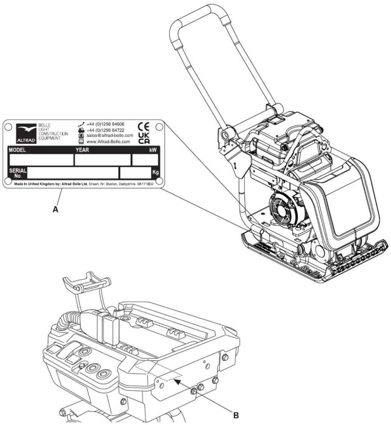
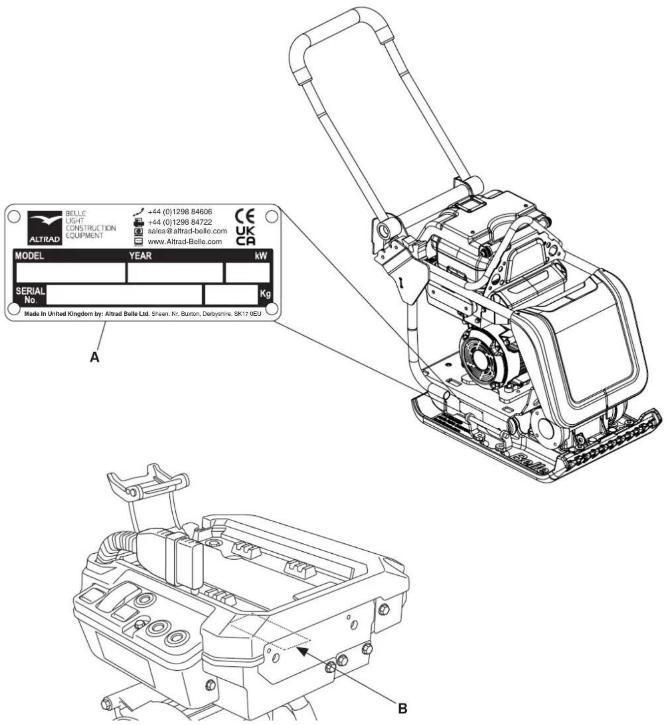
ENSURE you make a note of the serial numbers of your machine and always quote them in any communication with Altrad Belle or one of our dealers.
A - MACHINE SERIAL NUMBER
B - POWER UNIT SERIAL NUMBER
text_image
BELLE LIGHT CONSTRUCTION EQUIPMENT +44 (0)1298 84606 +44 (0)1298 84722 sales@altrad-belle.com www.Altrad-Belle.com CE UK CA MODEL YEAR kW SERIAL No. Kg Made In United Kingdom by: Altrad Belle Ltd. Sheen. Nr. Buxton, Derbyshire. SK17 0EU A BGENERAL
Heavyweight, professional combination compaction plate designed with an emission free, Li-ion battery powered motor for all your compaction requirements, indoor usage and poorly ventilated areas.
Produces low HAV values and matches the high performance compaction of its petrol powered equivalent, but without the environmental impact...Building a Sustainable Future!
STANDARD OPERATION
The machine is intended to be used for the following, in safe environmental conditions as described in this manual.
• Cohesive materials (less than 20% granular) e.g clay, silt & heavy soils.
• Granular materials (more than 20% granular) e.g hard core, sand & light soils.
- Bituminous materials e.g asphalt (tarmac), cold lay (bitumin emulsion products).
Any other use is not deemed suitable for this machine. Altrad Belle will not liable for any damage or injury resulting from any use other than outlined above. The operator will be liable.
Any unauthorised modifications or attachments are prohibited. They may affect the performance and safety of the machine, potentially resulting in damage to the machine or injury to the operator.
Use of non-genuine replacement parts may also affect the performance and safety of the machine. potentially resulting in damage to the machine or injury to the operator.
DANGER ZONE
The danger zone is the area around the machine in which persons are endangered during standard operation as outlined above.
During operation of the machine, cordon off the work area and keep members of the public and unauthorized personnel at a safe distance away from the danger zone.
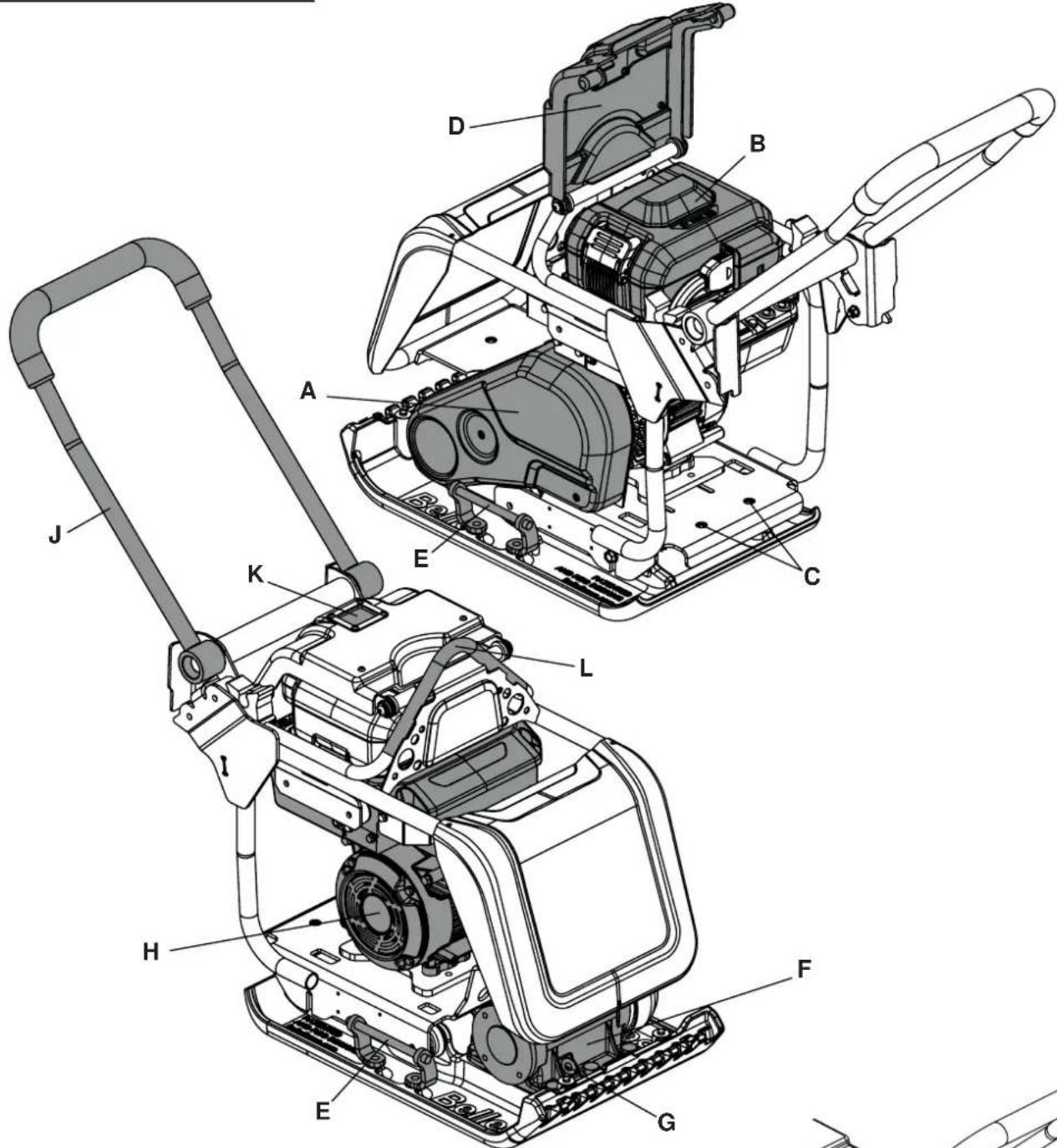
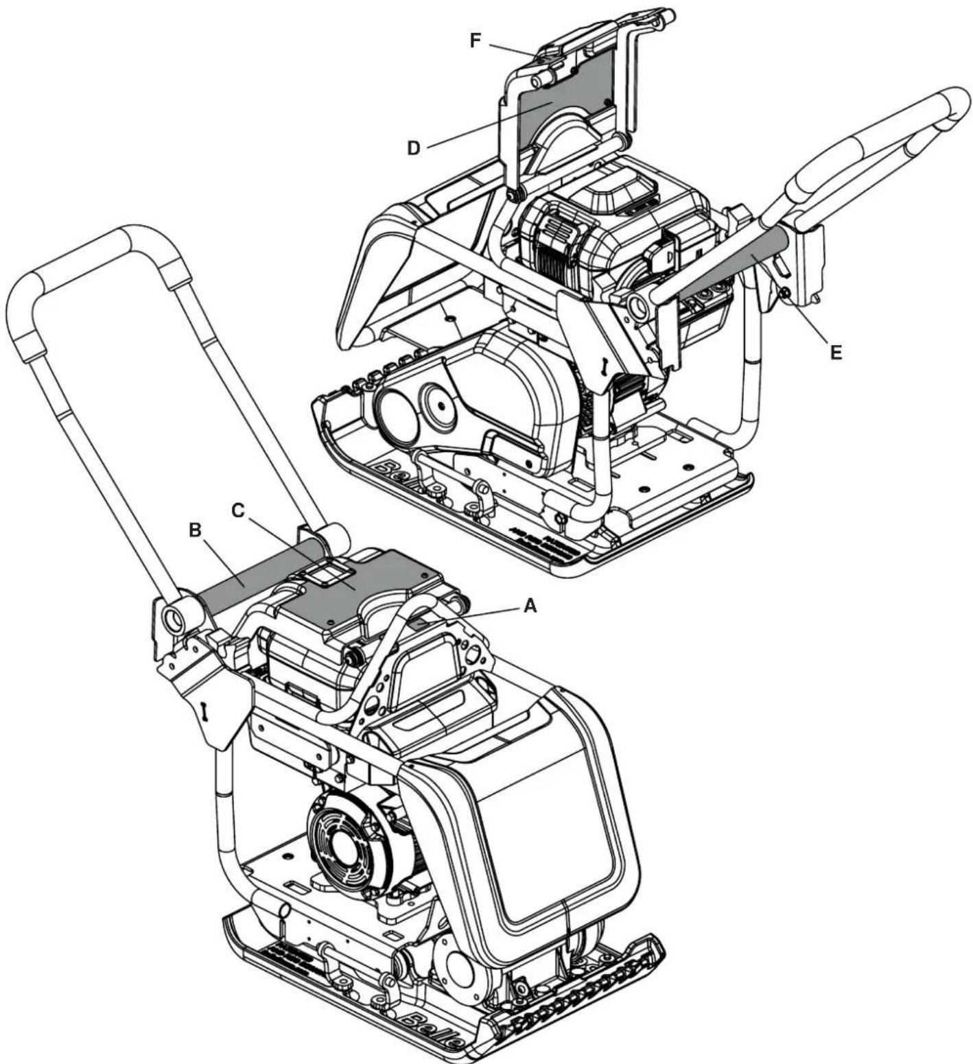
MAIN COMPONENT LOCATIONS
text_image
Technical diagram of a mechanical device with labeled parts from A to L, showing exploded and assembled views.A. Belt Guard.
B. Battery Pack (See Page 8).
C. Attachment Points for Optional Wheel Kit.
D. Protective Battery Cover.
E. Hand Lifting Points.
F. Vibrator / Vibrator Housing.
G. Vibrator Oil Check Plug.
H. Power Unit (See Page 8).
J. Control Handle.
K. Battery Charge Level Viewing Window.
L. Lifting Eye.
M. Wheel Kit Assembly.
N. Handle Clip.
P. Handle Clip Locating Plunger.
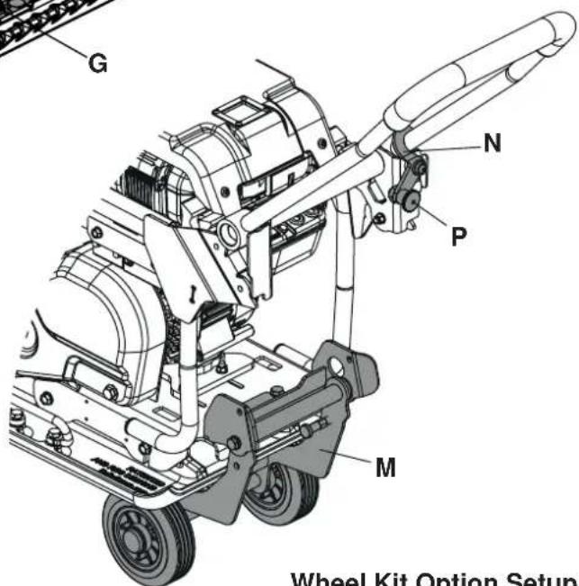
text_image
G N P M Wheel Kit Option SetupWheel Kit Option Setup
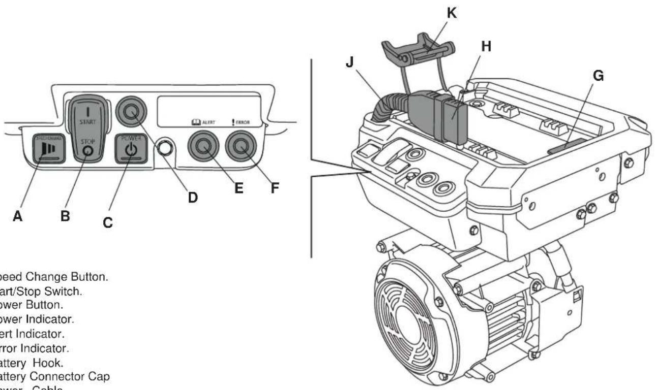
POWER UNIT COMPONENTS
text_image
A B C D E F START STOP POWER ALERT ERROR Speed Change Button. Start/Stop Switch. Power Button. Power Indicator. Alert Indicator. Mirror Indicator. Battery Hook. Battery Connector Cap Power. Cable K H G JA. Speed Change Button.
B. Start/Stop Switch.
C. Power Button.
D. Power Indicator.
E. Alert Indicator.
F. Error Indicator.
G. Battery Hook.
H. Battery Connector Cap
J. Power Cable.
K. Battery Retaining Lever.
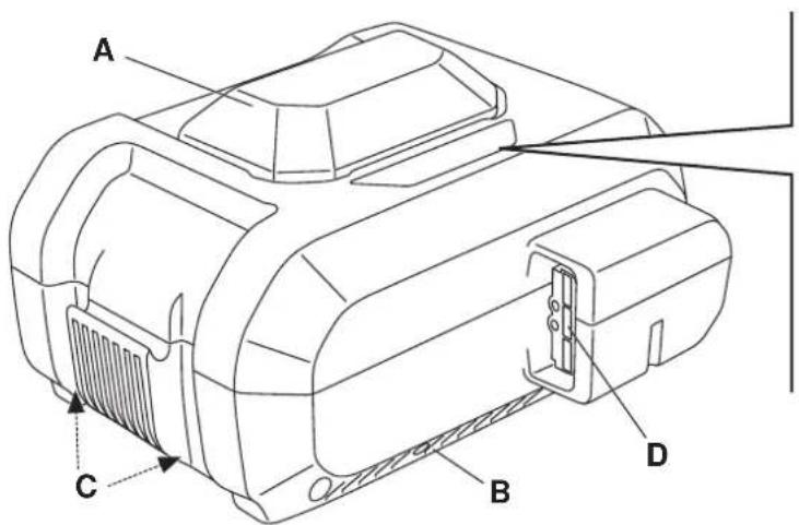
BATTERY PACK COMPONENTS

text_image
A C B D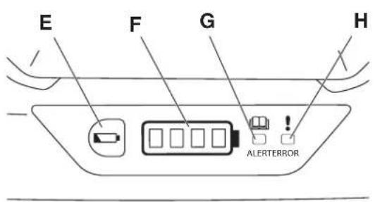
text_image
E F G H - ALERTERRORA. Handle.
B. Intake Port (both sides).
C. Exhaust Port (bottom).
D. Battery Connector.
E. Charge Level Check Button.
F. Charge Level Indicator.
G. ALERT Indicator.
H. ERROR Indicator.
BATTERY CHARGER
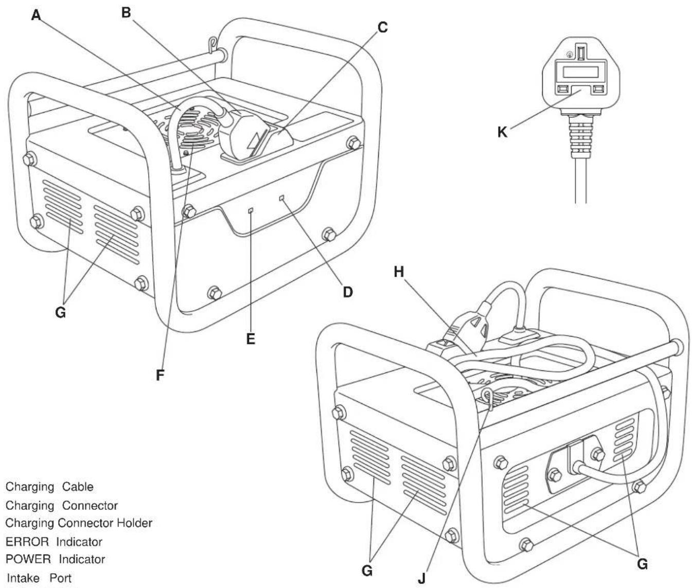
A. Charging Cable
B. Charging Connector
C. Charging Connector Holder
D. ERROR Indicator
E. POWER Indicator
F. Intake Port
G. Exhaust Port
H. AC Cable
J. AC Plug Holder
K. AC Plug
STATIC DIMENSIONS
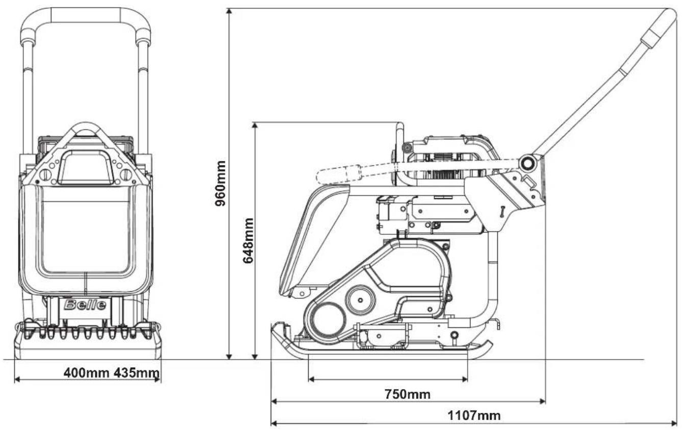
| Model PCX 13/40E+ | |
| ** Motor (Hp / kW) 2.2 / 1.6 | |
| Vibrator Force (KN) 13 | |
| Frequency (Hz) 101 | |
| Static Pressure (kg/m2) 560 | |
| Max Gradient (°) 20 | |
| Travel Speed (m/min) 20 | |
| * HAV Level (m/s2) <2.5 | |
| Weight (kg) 89 | |
| Motor RPM: 3600 / 3000 / 2800 | |
| Sound Power Level (dB(A)) | 101 |
* Minimum level to EN500 Part 4.
** The power rating of the petrol engines indicated in this document is the net power tested on a production petrol engine for the petrol engine model and measured in accordance with SAE J1349 at a specified rpm.
Mass production petrol engines may vary from this value. Actual power output for the petrol engine installed in the final machine will vary depending on numerous factors, including the operating speed of the petrol engine in application, environmental conditions, maintenance and other variables. Honda reserves the right to modify its specifications at any time and without notice.
| Model Honda eGX Battery | |
| Battery Type Li-Ion | |
| Weight (kg) 6.4 | |
| Dimensions LxWxH (mm) 268 x 233 x 150 | |
| Voltage: (V) 72 | |
| Energy Rating (Wh) 720 | |
| Energy Capacity (Ah) 10 | |
| Charge Time (Hr) 1.10 |
| Model Honda eGX Battery Charger | |
| Dimensions LxWxH (mm) 266 x 352 x 247 | |
| Weight (kg) | 11 |
| Input Voltage AC (v) 100 to 240 | |
| Input Frequency (Hz) 50 / 60 | |
| Output voltage DC (v) 82.8 | |
| Output current (A) | 8.5 |
| Batteries that can be charged | DP72104Z |
| Charging temperature range (°C / °F) | 5 to 30 / 41 to 86 |
GENERAL SAFETY
For your own personal protection and for the safety of those around you, please read and ensure you fully understand the following safety information. It is the responsibility of the operator to ensure that he/she fully understands how to operate this equipment safely. If you are unsure about the safe and correct use of the machine, consult your supervisor or Altrad Belle.

WARNING
Improper maintenance can be hazardous. Read and Understand this section before you perform any maintenance, service or repairs.
This machine is designed to eliminate the possible risks arising from the use of it. However, risks DO reside, and these residual risks are not clearly recognizable, and may cause personal injury or property damage, and possible death. If such unpredictable and unrecognizable risks become apparent, the machine must be stopped immediately, and operator or his supervisor must take appropriate measure to eliminate such risks. It is sometimes necessary that the manufacturer must be informed of such event for future counter measuring.
ALWAYS keep the Operator's Manual and any other manuals that accompany this machine to hand. Immediately replace any manuals that may have been lost or are now illegible.
PRE-START CHECKS
The following Pre-start-up inspection must be performed before the start of each work session or after every four hours of use, whichever is first. Please refer to the service section for detailed guidance. If any fault is discovered, the machine must not be used until the fault is rectified.
- Thoroughly inspect the machine for signs of damage. Check components are present and secure.
- ENSURE there is no debris or excessive dirt present on the machine.
- ENSURE the battery pack is securely attached to power unit and the power cable is connected.
- ENSURE the battery pack is sufficiently charged.
Once all the above checks have been made, test run the machine checking that all switches function correctly and all indicators light when the power unit is turned on.
WORKSITES
- ENSURE the operator is familiar with the working surroundings. Worksites can be hazardous.
• ALWAYS keep the work area tidy and clear of any obstructions that may lead to accidents and/or injuries.
• Cordon off the work area and keep members of the public and unauthorized personnel at a safe distance. - This machine is heavy and must not be lifted single-handedly, either GET HELP or use suitable lifting equipment. A Wheel Kit Transport option is also available for this machine (see our website Altrad-Belle.com)
- ENSURE the operator has had adequate training prior to use, is familiar with all controls and knows how to safely switch the machine OFF before it is switched ON in case you get into difficulty.
- Suitable PPE MUST be worn when using this equipment i.e. Safety Goggles, Gloves, Ear Defenders, Dust Mask and Steel Toe capped footwear (with anti-slip soles for added protection). Wear clothing suitable for the work you are doing and DO NOT wear loose jewellery that could be caught in moving parts
• ALWAYS inform colleagues of what you will be doing and where you will be working.
• DO NOT operate the machine when you are ill, feeling tired, or when under the influence of drugs / alcohol. - NEVER leave the power unit running and unattended.
- NEVER remove or tamper with any guards fitted, they are there for your protection. Always check guards for condition and security, if any are damaged or missing, DO NOT USE THE MACHINE until the guard has been replaced or repaired.
- When working on a gradient ALWAYS work up and down the slope, not across.
• ALWAYS proceed with caution when working around utilities (gas, water pipes electrical lines)
• ENSURE extra care is taken when working near to banks or trenches where there is a danger of the material collapsing. - When working within trenches or pits ALWAYS pay attention to the side walls as the vibration from the machine could cause them to collapse.
- Some vibration from the compaction operation is transmitted through the handle to the operator's hands. The Altrad Belle Plate Compactor range has been specifically designed to reduce hand/arm vibration levels. Refer to the Technical Data section for vibration levels and usage times (recommended maximum daily exposure time). DO NOT exceed the maximum usage times.
- The compacting process will occasionally produce dust, which may be hazardous to your health. Always wear a mask that is suited to the type of dust being produced.
BATTERY CHARGER
- To reduce risk of injury, charge ONLY DP72104Z type rechargeable batteries. Other types of batteries may burst causing personal injury and damage.
- This Battery Charger is not intended for use by children or persons with physical, sensory or mental limitations or a lack of experience or knowledge. DO NOT allow children to play with this Battery Charger - IT IS NOT A TOY!
- Charge only Li-ion Honda Battery Packs that have a capacity of 10 Ah with 80 battery cells. The battery voltage must match the battery charging voltage of the Battery Charger. DO NOT charge non-rechargeable Battery Packs, otherwise there is danger of fire and explosion.
- Continued use of the Battery Charger under unusual conditions could result in fire or electric shock, which may kill or seriously hurt you.
- DO NOT modify the Battery Charger. Modifying, disassembling or repairing the Battery Charger could result in fire or electric shock, which can cause death or serious injury. Disassembly and repairs require specialized knowledge, contact your servicing dealer.
- Before using the Battery Charger / charging a Battery Pack, people who are using an electronic medical device must confirm how their device might be affected. The electromagnetic radiation produced during charging may affect the operation of electronic medical devices, which may kill or seriously hurt you.
- If the Battery Pack leaks fluid or smells strangely, stop using it and compact your servicing dealer. Battery Pack contains combustible organic solvents as an electrolyte solution. Mistakenly handling them may result in burns or serious injuries.
DO NOT use the Battery Charger in the following situations.
- Locations where the Battery Charger becomes unstable.
- Locations where there is flammable gas or combustible materials
- Locations that are very cold or very hot, such as in direct sunlight or near a heater
- Locations exposed to water or excessive humidity
- Locations where children or pets might play with it
ALWAYS follow the rules below.
• DO NOT charge Battery Packs if there is the risk of a lightning storm.
• DO NOT charge if the electric outlet is loose.
• DO NOT charge if the Battery Charger, AC cable, or the electric outlet is damaged or deformed, dusty, dirty, or rusty.
• DO NOT plug too many power cords into one electric outlet.
• DO NOT charge while the AC cable is wound up.
- DO NOT stand on or place heavy objects on the Battery Charger or AC cable.
• DO NOT pull or repeatedly bend the AC cable or charging cable with an excessive force.
- DO NOT touch the Battery Charger or AC cable if your hands are wet.
- DO NOT splash or submerge the Battery Charger or AC cable in water.
- If the Battery Charger or AC cable is submerged in water while you are charging, do not touch the Battery Charger or AC cable. Contact your servicing dealer.
• DO NOT leave the AC plug plugged into the electric outlet after you finish charging.
• DO NOT pull on the cable when you pull out the AC plug.
• DO NOT subject the Battery Charger to excessive physical shock, such as by dropping or hitting it.
- DO NOT use the Battery Charger to charge anything except Honda Battery Packs. Use only authentic Battery Packs. Charging a non-authentic Battery Pack could damage it and the charger because of poor protection functions, etc.
- DO NOT touch the Battery Pack terminals with metal. Mishandling them could result in electric shock or fire, which may kill or seriously hurt you. Follow the procedures and instructions provided in the manufacturers manual.
BATTERY PACK
• ALWAYS use a genuine battery pack that is intended for this machine.
DO NOT touch the Battery Pack's connectors with metal objects or insert metal objects through openings into the Battery Pack.
- ALWAYS keep the battery pack clean and dry.
• NEVER allow the battery pack to come into contact with water.
- If the Battery Pack leaks fluid or smells strangely, IMMEDIATELY move it away from any heat sources or flame. There is a risk of fire or rupturing if the leaked liquid or gas ignites.
- The Battery Pack contains combustible organic solvents as an electrolyte solution. If the liquid gets into your eyes, rinse them with plenty of water. After that, IMMEDIATELY seek medical care.
• DO NOT allow children to use the Battery Pack. Store the Battery Pack out of the reach of children.
• DO NOT store the Battery Pack in a damp location. Doing so can cause a malfunction.
- When the Battery Pack is not in use, keep it away from other metal objects, like paper clips, coins, keys, nails, screws or other small metal objects, that can make a connection from one terminal to another. Shorting the battery terminals together may cause burns or a fire.
- In case of fire, STOP using the machine immediately and extinguish with dry chemical, sandy soil, carbon dioxide or appropriate foam.
• The Battery Pack will deteriorate if it is repeatedly charged and discharged, as well as if it is stored and not used.
- As the Battery Pack deteriorates, its full-charge capacity decreases and the length of time it can be used shortens. Once the full-charge capacity is reduced by deterioration, it cannot be recovered and cannot reach the charging capacity of a new Battery Pack.
• ALWAYS remove the battery pack from the power unit when carrying or checking it.
• ONLY charge the battery pack in a recommended charging unit.
• DO NOT expose the battery pack to extreme temperatures (below 5°C (41°F) or above 40°C (104°F))
- NEVER attempt to service a damaged battery pack.
• WORK ON THE BATTERY PACK OR POWER UNIT MUST ONLY BE CARRIED OUT BY QUALIFIED PERSONNEL.
WEATHER CONDITIONS
• We recommended that this machine not be used in heavy rain.
• Rain can alter the condition of the worksite surface area. ALWAYS be aware of the condition of the surface after it has rained.
- Operating the machine in poor visibility can result in serious injury or even death. ALWAYS use your lights to improve the visibility of the area.
- NEVER operate the machine in temperatures below 5°C (41°F) or above 40°C (104°F)
DURING MAINTENANCE
• ALWAYS remove the battery before carrying out any maintenance on the machine.
- Carry out maintenance and repair work only if the machine is positioned on stable and level ground and has been secured against inadvertent movement.
- NEVER service the machine while the power unit is running, always switch OFF.
- Clean the machine, especially connections and threaded unions, before carrying out maintenance/repair.
- When dismantling assemblies containing components under pressure from springs, always wear suitable PPE. This will protect against eye injuries from accidental flying components.
- When handling oil, grease and other chemical substances, observe the product related safety regulations.
AFTER MAINTENANCE
• ALWAYS tighten any screwed connections that have been loosened during maintenance and repair.
- Any safety devices removed for set-up, maintenance or repair purposes must be refitted and checked immediately upon completion of the maintenance and repair work.
• ENSURE that all consumables and replaced parts are disposed of safely and with minimum environmental impact.
MODIFICATIONS & REPLACEMENT PARTS
- NEVER make any modifications or additions to the machine without the prior approval of Altrad Belle. Any unapproved modifications may affect the performance and safety of the machine. This may also void the Warranty.
- ALWAYS use genuine Altrad Belle replacement parts. Use of non-genuine replacement parts may affect the performance and safety of the machine. This may also voide the Warranty.
Genuine Altrad Belle replacement parts can be purchased online at www.Altrad-Belle247.com
SAFETY DECALS
text_image
Technical diagram of a mechanical device with labeled parts A through FA. Lifting Point Decal
B. Low HAV Decal.
C. General Safety / Info Decal.
D. Operating Instructions Decal.
E. Handle Latch Decal
F. Speed Setting Decal
SAFETY DECALS
A - Lifting Point Decal
Lifting point for use with a Sling or Mechanical Hoist.
B. Low HAV Decal.
Highlights that the machine has a HAV level low enough that it can be used for more than 8hrs.
C. General Safety / Info Decal.

Read the Operators Manual

Wear Ear Protection

Wear Eye Protection

Wear Protective Footwear
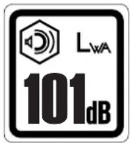
*Indicates the Noise Level of the Machine
* Also see Technical Data section for Noise Level for this machine.
D. Operating Instructions Decal.
Includes information on how to Start and Stop the Power Unit.

natural_image
Prohibition sign showing a showerhead spraying water over a circular background (no text or symbols)DO NOT Jetwash the Machine
E. Handle Latch Decal.
The Handle Latch is not required when the Wheel Kit is not in use.
- Disengage the Wheel Kit.
- Pull the plunger and rotate the latch anti-clock wise to its stop position. Release the plunger to lock the latch in the unlock position.
The Handle Latch is ALWAYS required when the Wheel Kit is engaged.
- Pull the plunger and rotate the latch clock wise until it locates over the handle tube. Release the plunger to lock the latch in the lock position.
- Engage the Wheel Kit.
F. Speed Setting Decal.
Highlights that the compactor has 3 speed settings which can be altered by pressing the 'Speed Chage' button on the power unit.

CAUTION
The compactor ALWAYS starts on the fastest speed when the power unit turned ON.
REASONS FOR COMPACTION
Soil, which has been disturbed or new infill, subbase and blacktop, will have small voids or air pockets which, if not compacted, will lead to one or more problems occurring.
- As traffic crosses the surface of an uncompacted area, the material is compressed. This leads to subsidence of the top surface as the material fills the voids.
- A similar situation occurs with static loads on uncompacted ground. The load (e.g. a building) will sink.
- Materials with voids are more susceptible to water seepage, leading to erosion. Water ingress may also cause the soil to expand during freezing temperatures and contract during dry spells. Expansion and contraction is a major cause of damage to building foundations and normally leads to the structure requiring underpinning.
Compaction increases the density of the material and therefore increases its load bearing capacity. Reduces air voids and therefore reduces the risk of subsidence, expansion and contraction, due to ingress of water.
APPLICATIONS
Applications/materials fall into three categories:
- Cohesive materials (less than 20% granular) e.g clay, silt & heavy soils.
- Granular materials (more than 20% granular) e.g hard core, sand & light soils.
- Bituminous materials e.g asphalt (tarmac), cold lay (bitumin emulsion products).
The chart shows the HAUC specifications for layer depth and number of passes for Dual Force' plates. If standard machines are used, optimum compaction can not be guaranteed, however, if layer depths are reduced and number of passes increased, results can be improved.
Moisture content of cohesive & granular materials is critical to effective compaction. If granular material is too dry it will flow around the plate instead of compacting. If the moisture content is too high the material may dry out after compaction and shrinkage will occur.
| 1400 - 1800 kg/m2 | COMPACTION PASSESS REQUIRED PER LAYER OF COMPACTED THICKNESS UP TO. | ||||
| 40mm 60mm | 80mm 100mm | 150mm | |||
| Cohesive Materials** | 2** | 4** | 5** | 6** | Reduce Layer Thickness |
| Granular Materials | 2* | 3* | 4* | 5 | 9 |
| Bituminous | 6 | 10 | 12 | Reduce Layer Thickness | |
* Usually placed in 100mm minimum layer so not specified by HAUC.
** The nature of cohesive materials makes plate compaction difficult. Optimum compaction is not guaranteed and not recommended by HAUC.
CHARGING THE BATTERY PACK
Refer to the Battery Charger manual for instructions on how to charge the Battery Pack.
ATTACHING THE BATTERY PACK

CAUTION
ALWAYS make sure to use a genuine, recommended Battery Pack.
Refer to the Machine Description section to identify the components.
- Make sure there is no debris or dirt on the battery tray.
- Tilt the Battery Pack and insert its claw into the battery hook.
- Push down the Battery Pack and hook the battery fastener to it.
- Push the battery fastener lever up and lock the Battery Pack. Be careful not to catch your fingers.
- Remove the battery connector cap from the power cable. Connect the power cable to the battery connector of the Battery Pack.
STOPPING THE POWER UNIT
Refer to the Machine Description section to identify the components.
- Press the START/STOP switch to the STOP position. The DC Power Unit will stop and the POWER indicator turns off.
Refer to the Machine Description section to identify the components.
- Press STOP on the START/STOP switch.
- Press the POWER button.
All the indicators should illuminate for a few seconds, and then only the POWER indicator remains illuminated. - Press the START/STOP switch to the START position to start the Power Unit.
- Push the SPEED CHANGE button to set the Power Unit speed as required.
- If the POWER button is pressed when the START/STOP switch is in the START position, the POWER indicator remains off and the ALERT indicator flashes. In this case, the Power Unit cannot start. Press the START/STOP switch to the STOP position and then press the POWER button.
- It may take some time for the indicators to light after the POWER button is pressed. If the indicators do not light, press the POWER button again.
- If the Power Unit is not operated for about one minute after the POWER button is pressed, the POWER indicator turns off. Press the POWER button again to start the Power Unit.
REMOVING THE BATTERY PACK
Refer to the Machine Description section to identify the components.

CAUTION
ENSURE the machine is switched OFF before removing the battery.
- Remove the power cable from the Battery Pack.
- Pull the battery fastener down to unlock, tilt the Battery Pack up and pull the Battery Pack claw out from the battery hook, and remove the Battery Pack.
- Attach the battery connector cap to the power cable.
CHECKING THE CHARGE LEVEL OF THE BATTERY PACK
While the Power Unit is operating, the charge level indicator lights or flashes so you can confirm the charge level of the Battery Pack.
While the Power Unit is stopped, press the charge level check button to confirm the charge level of the Battery Pack.
| Indicator Display | Charge Level | |
 | High↓Low | Fully charged. |
 | Sufficiently charged. | |
 | Remaining battery power is low.Charge the Battery Pack. | |
 | ||
 | ||
■:On, :Off : Flashing, □
TRANSPORTATION

CAUTION
We RECOMMEND removing the battery pack from the power unit before transporting the machine.
Transporting the machine is a 2 person operation. Use the provided Hand Lifting Points (See Machine Description section) DO NOT use a Mechanical Hoist on the Hand Lifting Points.
Where it is necessary to use lifting equipment to transport the machine, make sure the lifting equipment has a WLL (Working Load Limit) suitable for the machines weight (see Technical Data section). Attach suitable chains or slings ONLY to the lifting point on the top of the machine.
If using the optional Wheel Kit attachment the handle latch must ALWAYS be engaged using the following procedure.
- Pull the plunger and rotate the latch clock wise until it locates over the handle tube. Release the plunger to lock the latch in the lock position.
The Wheel Kit can now be fitted as per the instructions provided with the Wheel Kit. Then tilt the machine forward to raise the transport wheels off the ground and underneath the baseplate. Then slowly lower the machine on top of the wheels.
To disengage the handle latch when the Wheel Kit is not in use, use the following procedure:-
- Pull the plunger and rotate the latch anti-clock wise to its stop position. Release the plunger to lock the latch in the unlock position.

CAUTION
ALWAYS pull the machine backwards when using the optional Wheel Kit attachment.
Having carried out the Pre-Start Checks listed in the Safety Instructions section of this manual, you may start the power unit.
The vibrator will not only cause the baseplate to vibrate but will also cause the machine to travel forward. During normal operation you should not have to push the machine forwards but allow it to travel at its own pace. The speed of travel will be determined by the condition of the surface being compacted.
If the surface to be compacted is on a slope, great care must be taken when controlling the machine's direction of travel. If necessary, use a suitable rope attached to the machine at a low point on the chassis, to allow a helper to take part of the machine's weight. Work up and down a slope not across.
Work the compactor over the surface in an organised pattern until the required compaction has been achieved. Where there are a number of different layers to be compacted on top of each other, compact each layer individually.
If the machine is not to be used for an long period of time it must be stored correctly to prevent deterioration or damage occurring during this period.
Store the machine in a clean dry building with plenty of ventilation if possible. If you can only store outdoors, cover with a waterproof sheet / tarpaulin.
PREPARING THE MACHINE FOR STORAGE
- Clean the machine and remove all unwanted material / debris (See the Cleaning section on page 23).
- Dry the machine to remove any moisture.
- Apply grease to any moving parts / grease points.
- Examine the machine for any worn / damaged parts. Replace if necessary.
STORING THE MACHINE
- Place the machine safely on stable, level ground.
ENSURE there is sufficient room around the machine to be able to carry out any service or maintenance procedures during the storage period. - Remove the battery pack and store correctly (See page 19)
DURING STORAGE
To prevent the build up of rust and to minimise the risk of seizures, periodically operate all machine functions during storage.
- Install a fully charged battery.
- Start the power unit.
- Operate all machine functions. ENSURE they all operate correctly.
- Re-do storage procedure from above.
REMOVING THE MACHINE FROM STORAGE
- Install a fully charged battery.
- Carry out the Pre-Start Check procedure (See page 12)
GENERAL
This machine is designed to give many years of trouble free operation. It is, however, important that the simple regular maintenance listed in this section is carried out. All maintenance procedures must be carried out by a competent, suitably qualified person.
A poorly maintained machine could be a danger to the operator and the other personnel on the worksite. ENSURE that the regular maintenance procedures listed in this manual are performed correctly and on time to keep the machine safe and efficient.
ALWAYS use genuine Altrad Belle replacement parts, the use of spurious parts may void your warranty.
Before any maintenance is carried out on the machine, switch off the machine and ALWAYS set the machine on stable, level ground.
ENSURE any faults identified during maintenance procedures are addressed and corrected immediately.
| Routine Maintenance (1) Each Use Every 5 Years or 250 Hours | ||||
| Exterior Check | √ | |||
| Switch Check | √ | |||
| LED Check | √ | |||
| Power Cable Check | √ | |||
| Motor Wire Harness Check | √ | |||
| Wires Harness Check | √(2)(4) | |||
| Battery Fastener | Check | √ | ||
| Replace | √(2) | |||
| Rubber Support | Check | √ | ||
| Replace | √(2) | |||
| Battery Hook | Check | √ | ||
| Replace | √(2) | |||
| Set Speed | Rated Speed Check | When Required (3)Medium Speed Check | ||
| Low Speed Check | ||||
(1) Perform at every indicated time or operating hours interval, whichever comes first.
(2) These items should be serviced by your servicing dealer, unless you have the proper tools and are mechanically proficient. Consult Altrad Belle.
(3) Speed is set to 3600 min^-1(rpm) (rated speed), 3300 min^-1(rpm) (medium speed) or 3000 min^-1(rpm) (low speed). If the Power Unit makes an unusual sound, have it inspected by your servicing dealer.
(4) Replace if necessary.
Service and Maintenance
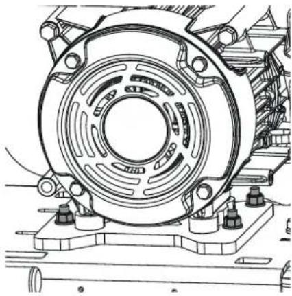
DRIVE BELT
Remove the belt guard then check the belt tension by placing light finger pressure on the top of the belt, as near central between the power unit drive and vibrator pulley. The belt should deflect by between 5mm and 10mm.
If the belt tension requires adjustment, remove the belt. Loosen the four power unit mounting bolts (Highlighted Grey in the adjacent diagram (1 bolt is hidden by the power unit)) enough to allow the power unit to be moved. Once set, refit the belt and check the belt tension a second time. If the belt tension is correct, retighten the power unit mounting bolts. If the Belt remains loose, replace the belt.
Finally, replace the belt guard ensuring it is correctly and securely fitted.
natural_image
Technical line drawing of a mechanical assembly with concentric gears and mounting base (no text or symbols)VIBRATOR UNIT
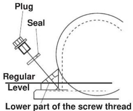
Place the machine safely on stable, level ground. Remove the plug complete with seal, check that the oil level reaches the bottom thread on the oil plug hole. Top up as necessary with the correct oil (see chart below).
text_image
Plug Seal Regular Level Lower part of the screw threadComponent Oil Type Quantity
Vibrator
Keeping the machine clean is an integral part of the service and maintenance program. The build-up of mud, dirt and debris could potentially affect the operating safety of the machine, exposing both the operator and other personnel to potentially hazardous situations.

WARNING
NEVER use a hose or pressure washer to spray water on the machine while cleaning it. Water entering the components may cause a malfunction and/or injury.
ALWAYS clean the machine using compressed air and wipe the battery pack clean with a dry, clean cloth. Before cleaning the Battery Pack, remove it from the specified device or the Battery Charger.
After the cleaning process check that all cables, hoses and fasteners are in place and secure. Replace any if necessary. Also ENSURE that all safety / warning decals are present in their correct locations. Replace any if necessary.
| Problem Cause Remedy | ||
| Power Unit does not operate. | Battery Pack is not attached correctly | Refer to “Attaching The Battery Pack” section and check that the power cable and Battery Pack are attached correctly. |
| Battery power is low. Charge the Battery Pack. | ||
| Battery Pack has malfunctioned. Replace the Battery Pack. | ||
| ALERT indicator is flashing. | Protection function is engaged. | Contact Agent or Altrad Belle. |
| When starting the Power Unit, the POWER button was pressed while the START/STOP switch was in the START position. | Press the START/STOP switch to the STOP position and then press the POWER button. | |
| The Power Unit becomes too hot.(POWER indicator lights) | Stop using the machine and let the Power Unit cool down. | |
| ERROR indicator is lit. | Protection function is engaged. Contact Agent or Altrad Belle. | |
| Machine will not vibrate. | Power Unit speed too slow. Contact agent or Altrad Belle. | |
| Drive belt tension loose. Adjust belt tension. | ||
| Drive failure. Contact Agent or Altrad Belle. | ||
| Vibrator failure. Contact Agent or Altrad Belle. | ||
| Asphalt adhering to plate. | Lack of lubrication. Use a water spray system. | |
| Paving blocks damaged. | Plate in direct contact with material. Use a paving pad. | |
| Bituminous surface flaking (laminating). | Over compaction. Remove and relay. | |
| Low travel speed (plate sinking). | Layer thickness too deep. Remove some of the material. | |
| Moisture content too high or too low. | Remove material and adjust. |
BATTERY PACK
| Indicator | Cause Remedy | |||
| ALERT ERROR | Charge Level | |||
| Flash - | - Problem was detected. | Remove all equipment connected to the Battery Pack, wait for about 5 minutes and press the Charge Level Check Button.When the ALERT indicator does not flash, the Battery Pack can be used normally. | ||
| 4 indicators flash | Problem was detected. (Overvoltage protection) | After following the instructions for the Battery Pack problem, connect the specified device and check if it works properly.When the device works, the Battery Pack can be used normally. | ||
| 1 indicators flash | Problem was detected. (Low voltage protection) | After following the instructions for the Battery Pack problem, connect the Battery Charger and check if the charging starts properly.When the charging starts, the Battery Pack can be used normally. | ||
| - | Illuminate | - | Problem with the specified device or Battery Charger, or malfunction in the Battery Pack was detected. | Remove all equipment connected to the Battery Pack, wait until all indicators turn off and press the Charge Level Check Button.When the ERROR indicator does not illuminate, the Battery Pack can be used normally.Check that there is no foreign material around the Battery Pack. Connect the specified device or Battery Charger.When the ERROR indicator illuminates, there is a problem with the specified device or Battery Charger. |
| Flash Malfunction was detected. Battery Pack is dead. | Replace the Battery Pack. | |||
BATTERY CHARGER
| Problem Cause Remedy | ||
| Charging does not start | The AC plug is not connected to an electric outlet. | Connect the AC plug to an electric outlet correctly. |
| The charging connector is not connected to the battery connector. | Connect the charging connector to the battery connector correctly. | |
| Charging stops midway | The Battery Pack is not being cooled correctly, so charging is stopped by the high-temperature protection function. | Position the Battery Pack so there are no gaps between the intake port of the Battery Charger and the exhaust port of the Battery Pack. |
| ERROR indicator is lit Protection function is engaged. Contact Altrad Belle. | ||

Safe Disposal.
Instructions for the protection of the environment.
The machine contains valuable materials.
Take the discarded apparatus and accessories to the relevant recycling facilities.
| Component Material | Component Material | |||
| Handle Steel Battery Pack *See Below | ||||
| Plastic Covers / Guards | HDPE | Battery Charger | *See Below | |
| Main Frame | Steel | Flexible Mounts | Steel and Rubber | |
| Baseplate | Steel | Various Parts | Steel and Aluminium | |
| Hand Grips | Rubber | Water Bottle (If fitted) | Plastic | |
| Power Unit | *See Below | |||
*DO NOT dispose of electric equipment together with household waste material.
If electrical appliances are disposed of in landfills or dumps, substances can leak and react and enter into the foodchain, damaging your health and well-being. For further information on the disposal of this product, please contact your dealer or your nearest domestic waste collection service.

Replacement Parts
When maintaining this product only the manufacturers original, genuine replacement parts may be used.
The user will lose any possible claims if replacement parts used are other than the makers original replacement parts.
Replacement parts for this product can be ordered online 24 hours a day, 7 days a week at www.Altrad-Belle247.com
For more information regarding the availability of replacement parts for this product, please contact Altrad Belle using the following contact details:-
Tel:- +44 (0)1298 84606
Fax:- +44 (0)1298 84073
Email:- sales@altrad-belle.com
Alternatively, please scan the adjacent QR Code (Quick Response Code) using your smartphone to access the Altrad Belle online parts portal.

Your new Altrad Belle 'PCX 13/40E+' Single Direction Plate Compactor is warranted to the original purchaser for a period of one-year (12 months) from the original date of purchase. The Altrad Belle warranty is against defects in design, materials and workmanship.
The following are not covered under the Altrad Belle warranty:
- Damage caused by abuse, misuse, dropping or other similar damage caused by or as a result of failure to follow assembly, operation or user maintenance instructions.
- Alterations, additions or repairs carried out by persons other than Altrad Belle or their recognised agents.
- Transportation or shipment costs to and from Altrad Belle or their recognised agents, for repair or assessment against a warranty claim, on any machine.
- Materials and/or labour costs to renew, repair or replace components due to fair wear and tear.
The following components are not covered by warranty.
- Drivebelt/s
Please also consult the Honda DC Power Unit, Battery & Battery Charger manuals for further information on their warranty details.
Altrad Belle and/or their recognised agents, directors, employees or insurers will not be held liable for consequential or other damages, losses or expenses in connection with or by reason of or the inability to use the machine for any purpose.
Warranty Claims
All warranty claims should firstly be directed to Altrad Belle, either by telephone, by Fax, by Email, or in writing.
For warranty claims:
Tel: +44 (0)1298 84606
Fax: +44 (0)1298 84073
Email: warranty.dept@altrad-belle.com
Write to:
Altrad Belle Warranty Department,
Sheen, Nr. Buxton,
Derbyshire,
SK17 0EU
England.
Warranty Registration:
In the bid for Altrad Belle to become greener and more eco friendly, we have now introduced online Warranty registration. To access the registration page of our website, please use the following address:-
http://www.bellegroup.com/index.php?p=warranty\_registration
Alternatively, please scan the adjacent QR Code (Quick Response Code) using your smartphone to access the registration page.

text_image
QR code image containing encoded data, no visible human-readable textSOMMAIRE PAGE
DÉCLARATION DE CONFORMITÉ UKCA 2
DÉCLARATION DE CONFORMITÉ CE/UE 4
INTRODUCTION....33
AVERTISSEMENT 33
Numéros de série 34
DESCRIPTION DE LA MACHINE
Directives relatives aux annotations.
text_image
Technical diagram of a mechanical device with labeled parts from A to J, showing exploded and assembled views.A. Protège-courroie
text_image
Technical diagram of an electric motor with labeled components including J, K, H, and G.COMPOSANTS DU BLOC-BATTERIE
text_image
A C B D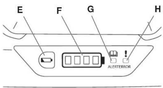
text_image
E F G H ALERTERRORtext_image
Technical diagram of a mechanical device with labeled parts A through F, showing assembly and component layout.A. Point de levage
natural_image
Prohibition sign showing a showerhead spraying water over a circular background (no text or symbols)natural_image
Technical line drawing of a mechanical assembly with no visible text or symbolsVIBRATEUR
Altrad Belle Warranty Department,
Sheen, Nr. Buxton
Derbyshire
SK17 0EU
England.
Angleterre
text_image
QR code image containing encoded data, no visible human-readable textÍNDICE NÚMERO DE PÁGINA
text_image
Technical diagram of a mechanical device with labeled parts from A to J, showing exploded and assembled views.text_image
Technical diagram of a mechanical device with labeled parts A through Ftext_image
Prohibition sign showing a showerhead spraying water, with no text or symbols beyond the graphic.natural_image
Technical line drawing of a mechanical component with concentric rings and mounting base (no text or symbols)UNIDAD VIBRADORA
Altrad Belle Warranty Department,
Sheen, No Buxton
Derbyshire
SK17 0EU
Inglaterra
Registro de Garantia :
text_image
QR code image containing encoded data, no visible human-readable textINHALT SEITENNUMMER
text_image
Technical diagram of a mechanical device with labeled parts from A to J, showing exploded and assembled views.A. Riemenschutz.
text_image
Technical diagram of a mechanical device with labeled parts A through Fnatural_image
Prohibition sign showing a showerhead spraying water over a circular background (no text or symbols)natural_image
Technical line drawing of a mechanical assembly with concentric gears and mounting base (no text or symbols)RÜTTELEINHEIT
Email : Warranty@belle-group.co.uk
Korrespondenzanschrift:
Altrad Belle Warranty Department,
Sheen, Nr. Buxton
Derbyshire
SK17 0EU
England
text_image
QR code image containing encoded data, no visible human-readable textSPIS TREŚCI NUMER STRONY
DEKLARACJA ZGODNOŚCI UKCA 2
DEKLARACJA ZGODNOŚCI WE/UE 7
WSTEP 105
OSTRZEŻENIE 105
Numery seryjne 106
OPIS MASZYNY
A. NUMER SERYJNY MASZYNY
B. NUMER SERYJNY MODUŁU ZASILANIA
text_image
BELLE LIGHT CONSTRUCTION EQUIPMENT +44 (0)1298 84606 +44 (0)1298 84722 sales@altrad-belle.com www.Altrad-Belle.com CE UK CA MODEL YEAR kW SERIAL No. Kg Made In United Kingdom by: Altrad Belle Ltd. Sheen. Nr. Buxton, Derbyshire. SK17 0EU A BINFORMACJE OGÓLNE
text_image
Technical diagram of a mechanical device with labeled parts from A to Ltext_image
Belle 400mm 960mm 648mm 435mm 750mm 1107mmMODYFIKACJE I CZEŚCI ZAMIENNE
text_image
Technical diagram of a mechanical device with labeled parts A through F, showing assembly and maintenance components.natural_image
Prohibition sign showing a showerhead spraying water, no text or symbols presentDO NOT Jetwash the Machine
natural_image
Technical line drawing of a mechanical assembly with no visible text or symbolsJEDNOSTKA WIBRACYJNA
Altrad Belle Warranty Department
Sheen, Nr. Buxton,
Derbyshire,
SK17 0EU
England.
text_image
QR code image containing encoded data, no visible human-readable text
BELLE
LIGHT
CONSTRUCTION
EQUIPMENT
ALTRAD BELLE
Sheen, Nr. Buxton, Derbyshire, SK17 DEU, GB
Tel. +44 (0)1298 84606 - Fax +44 (0)1298 84722 - Email: sales@altrad-belle.com
www.Altrad-Belle.com
EU IMPORTER ADDRESS