PE-5200 - Pump Sauermann - Free user manual and instructions
Find the device manual for free PE-5200 Sauermann in PDF.
| Product type | Peristaltic pump for condensate lifting |
| Flow rate | 6 L/h |
| Max discharge head | 12 m |
| Max suction head | 2 m |
| Supply voltage | 230 V~ 50/60 Hz |
| Motor power | 11 W |
| IP protection rating | 65 |
| Max ambient temperature | 50 °C |
| Delayed stop function | Yes, 3 minutes after compressor stop |
| Overflow alarm | NC contact 8 A / 250 V (included) |
| Detection type | Detection block with float and filter |
| Electrical connection | Via compressor signal (black wire) or via level detection |
| Test button | Yes, for 3 minutes of operation |
| Cleaning detection block | With water + 5% bleach solution |
| Pump tube replacement | Yearly or more often if necessary |
| Warranty | 2 years (excluding pump tube) |
Frequently Asked Questions - PE-5200 Sauermann
User questions about PE-5200 Sauermann
0 question about this device. Answer the ones you know or ask your own.
Ask a new question about this device
Download the instructions for your Pump in PDF format for free! Find your manual PE-5200 - Sauermann and take your electronic device back in hand. On this page are published all the documents necessary for the use of your device. PE-5200 by Sauermann.
USER MANUAL PE-5200 Sauermann
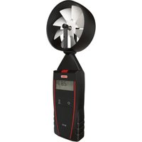
The PE range of Peristaltic pumps are designed to remove condensate water. They are particularly adapted for use in Air Conditioning, Evaporator & Refrigerated cabinet applications.
Characteristics:
□ Flow 6 l/h
- Max Discharge Head.: 12 m
- Max Suction Height: 2 m
□ Power Supply: 230 V\~ - 50/60 Hz
□ Motor Power Level: 11 W
□ IP 65
☐ Max Design Ambient Temperature: 50°C
0. SECURITY
0.1 In any case PE series peristaltic pumps have not to run continuously
0.2 Sauermann recommends to use a security system (Floating alarm ACC00601 NO/NC 10 Amp – 230 Vac (optional; see fig.8) or similar) allowing to stop the unit and prevent the overflowing whenever an excessive amount of condensate is produced. The PE 5200 pump is equipped with a NC 8 Amp – 250 V contact allowing this function.
0.3 Sauermann does not accept any responsibility in case of not respect of these recommendation
1. INSTALLATION
Warning: Before carrying out any operation on the pump, make sure the installation is disconnected from the power supply.
We recommend the pump be positioned with the suction & discharge spigots pointing downward.
➢ Installation with Mounting Bracket supplied (fig. 1)
- Fasten the Mounting Bracket with the screw & rawlplug supplied.
-
Slide the pump body onto the bracket.
-
POWER SUPPLY (fig. 2 and 4)
2.1 Connection to power supply
Connect the pump to the power supply using a circuit breaker (not included) to standard IEC 345 on live & neutral.
2.2 Connection for model PE 5000 (Cooling only, compressor signal) (fig. 2)
Connect the black cable to one of the supply phases of the compressor power supply (see fig.2) or of the three-way valve (chilled water applications) in order to start the pump whenever the air-handling unit is in cooling mode. The presence of a 230 V supply on the black cable starts the pump. When the compressor stops, the voltage drops to zero. The pump continues to operate for 3 minutes on overrun and stops.
In any case the black cable have not to be direct connected before the power switch. Otherwise the pump will run continuously (see chapter 0).
2.3 Connection for model PE 5100 (Heat-pump, temperature differential sensors) see (fig. 3)
Position Blue sensor cable to air-off side of the air handling unit & the Red sensor cable on the return-air side. The pump operates as soon as a temperature difference of 6^ ± 2^ is sensed. It will continue to operate as long as the temperature difference sensed is greater than 6^ ± 2^ . When the temperature difference sensed drops below 6^ ± 2^ , the pump will continue to operate on overrun for 3 minutes before stopping.
Warning:
- Temperature sensors must be placed in the air flow (red: suction; blue: delivery) and must not be placed in the condensate water or the false ceiling, or on the cooling tubes, for any reason.
- For VRF or VRV systems, the suction (red) temperature sensor must be positioned outside the heat exchange zone (e.g. on the split side or in an area at room temperature).
Failure to follow these instructions may cause the pump to malfunction or to run continuously (see chapter 0).
2.4 Connection for model PE 5200 (General Use, Remote Float Sensor) (see fig. 4)
Connect the interconnecting cable from the remote float sensor to the pump body.
The remote float sensor senses the presence of condensate & can start / stop the pump & send an alarm signal if it detects an abnormal amount in the sump.
Important: The alarm provided is an 8A/250V resistive NC contact. This can be used to stop the cooling cycle if an abnormal amount of condensate is detected & reduce the possibility of overflow accidents. Please consult & follow the air conditioning manufacturers electrical diagram & alarm connection recommendations at all times.
3. CONDENSATE CONNECTIONS
3.1 For models PE 5000 & PE 5100 (see fig. 2 and 3)
Condensate Removal
The suction end of the pump must be connected to the condensate tray fall pipe with the rubber adapter tube, reducer adaptor & clear tube supplied. The suction tube must be securely connected to the suction side of the pump (see mark on cover plate) with the tie wraps supplied.
3.2 For model PE 5200 (see fig. 4)
a) Condensate Removal
The remote float detection unit must be connected to the condensate tray fall pipe with the rubber adapter supplied.
b) Remote Float Detection Unit
The suction end of the pump (see mark on cover plate) must be connected to one of the two possible 7 mm connections on the remote float detection unit with clear 6 mm int. diam. tubing. The unused 7 mm connection on the float detection unit must be capped with the cap provided.
c) Breather Tube
The 4 mm diam. breather tube supplied must be connected to the top of the float detection unit such that the top of the free end of the tube is situated above the edge of the condensate tray.
d) Installation
Important: Install the float detection unit in a level attitude to ensure correct operation of the float (see fig.5).
3.3 Condensate Removal Pipe
The 6 mm diam. (1/4 inch braided or clear) condensate removal pipe must be securely connected to the discharge side of the pump (see exit mark on cover) with the tie wraps provided (see fig 2, 3 & 4). The waste end of the condensate removal pipe must terminate in an approved drain or waste water fall tube & may be connected to it with the Sauermann ACC00205 self-sealing fitting (not provided).
Start the air conditioning unit & pour a small amount of water into the condensate tray using the Sauermann ACC00401 priming squeeze bottle (not included) or other means.
Check that the pump is operating correctly & removing water from the tray by pressing the Test button situated on the side of the pump (see Fig.6). The pump will operate on overrun for three minutes & stop if correctly installed.
4.2 For model PE 5200
Pour a small amount of water into the condensate tray using the Sauermann ACC00401 priming squeeze bottle (not included). Check that the pump is operating correctly & removing water from the tray. If correctly installed, the pump should stop when the water level has decreased.
To check Alarm function, continue to pour water into the tray until the float rises sufficiently to trigger your chosen alarm feature (switch off compressor, visual or audible alarm...). This will depend on individual Installer preferences.
5. CLEANING & MAINTENANCE
WARNING: Before any intervention, switch off pump power supply at source.
5.1 Cleaning of remote detection unit for model PE 5200
The float detection unit & filter must be cleaned regularly with due regard to the prevailing levels & types of pollution in the operating environment of the unit.
Proceed as follows:
- Remove the cover from the detection unit body.
- Remove the metallic filter.
- Clean the detection unit & the filter body with a solution of water 5% bleach.
- Replace the filter & firmly replace the cover on the detection unit body.
Important: We recommend that after every service, the pump operation & alarm features should be tested as in Para 4 above to ensure serviceability.
5.2 Replacing worn pump head tube
Regularly inspect pump head tube & replace every 12 months or as required depending on the operating environment of the pump.
Warning: Be sure to disconnect the pump from the power supply to ensure it cannot start & potentially injure the engineer while the tube is being replaced.
5.2.1 Removal of pump head tube
- Disconnect the suction & waste tubes from the pump
- Remove the cover plate
- Rotate the roller assembly manually into a vertical position
- Remove the suction side connector from its housing by pulling upwards
- Keep pulling the tube upwards & remove it by rotating the roller assembly clockwise.
- The waste side connector can now be removed from its housing & the tube has successfully been removed.
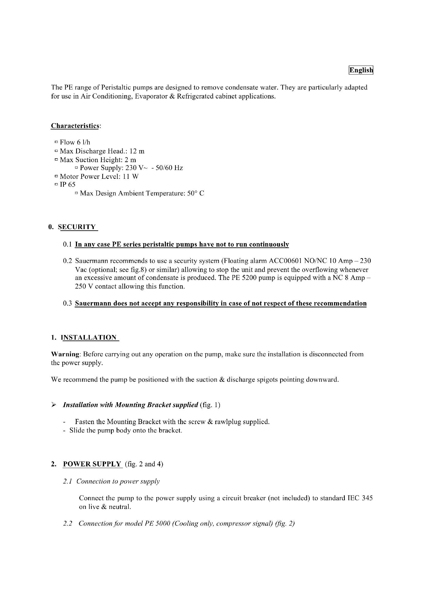
5.2.2 Fitting the replacement pump head tube (see fig.7)
- Insert the suction side (left hand) connector into its housing & place the tube in position with one hand. Rotate the roller assembly clockwise until the tube is seated correctly and insert the waste side (right hand) connector in its housing.
- Replace the protective cover plate in position.
- Note: Always test the pump after any intervention to ensure serviceability.
6. WARRANTY
6.1 Sauermann warranty for these products is 2 years from date of delivery. The warranty is strictly limited to the replacement or remanufacture of those parts that are defective or show defects in production. No other warranty is offered either explicitly or implicitly in respect of any other matter whatsoever.
6.2 Entire pumps, pump heads or components returned under warranty must be complete & accompanied by a note detailing the installation date, address & the defect observed by the engineer.
6.3 This warranty is not related to the membrane tube
6.4 We decline any responsibility whatsoever for pump failures in case of incorrect installation, not respect of these recommendations, poor or incorrect cleaning & maintenance or non-connection of an alarm contacts (ACC00601, optional) to prevent overflow in case of problems in removing condensate.
Please get attention to the used letters for the electrical connections
P
Live
Brown
N
Neutral
Blue
Phase
Marron
Neutre Bleu
Fase
Marrone
Neutro Blu
Fase
Marron
Neutro Azul
Phase
Braun
Nulleiter Blau
Фаза
Коричневый
Нейтраль
Синий
PE 5000 (220 - 240 V)
C
Cooling Signal (compressor)
Black
natural_image
Technical line drawing of a mechanical component with a red arrow pointing to a rectangular feature (no text or symbols)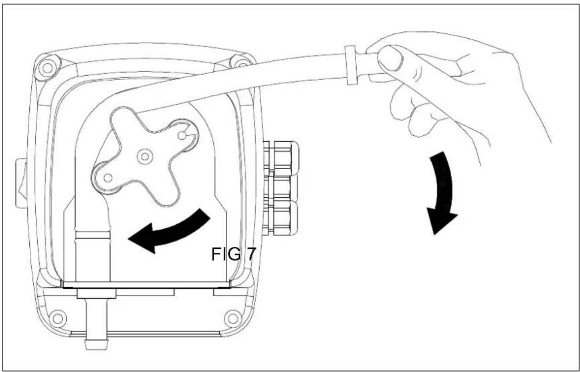
text_image
FIG 7
text_image
sauermann ACC 00601 115/230 Vac 10 A FIG 8 ACC00601Rouge/Red = Commun/Common
Noir/Black = NB
Blanc/White = NO