SiC320 - Industrial measuring instrument Sauermann - Free user manual and instructions
Find the device manual for free SiC320 Sauermann in PDF.
| Product type | Sensor-transmitter for industrial measurements |
| Brand | Sauermann |
| Model | SiC320 |
| Category | Industrial measurement instrument |
| Measured quantities | Differential pressure, temperature (Pt100, thermocouple), hygrometry, air quality (CO, CO₂, VOCs), air velocity, air flow, air change rate |
| Power supply | 24 V DC or 24 V AC (with converter) |
| Operating temperature | -10 °C to 50 °C (14 °F to 122 °F) |
| Storage temperature | -10 °C to 70 °C (14 °F to 158 °F) |
| Protection rating | IP66, resistant to VHP (vaporized hydrogen peroxide) |
| Mounting | Wall mounting on included 316L stainless steel plate |
| Analog outputs | Up to 4 outputs (0-4/20 mA or 0-5/10 V) |
| Communication | RS-485, optional wireless module, connection for PC software |
| Probe connectors | 2 connectors for external probes |
| Display | Models with or without touch screen; configuration via screen or app |
| Auto-zero function | Yes, by integrated solenoid valve |
| Compliance | Directive 2014/53/EU (radio equipment) |
| Maintenance and cleaning | Avoid aggressive solvents; protect the device when cleaning with formaldehyde-based products |
| Safety precautions | Electrical connection by qualified technician, device de-energized; switch/circuit breaker mandatory upstream |
| Spare parts and repairability | Contact customer service via the Customer Service Portal; parts available on request |
| Supplied accessories | Screws and wall plugs for mounting, stainless steel plate, cable glands |
Frequently Asked Questions - SiC320 Sauermann
User questions about SiC320 Sauermann
0 question about this device. Answer the ones you know or ask your own.
Ask a new question about this device
Download the instructions for your Industrial measuring instrument in PDF format for free! Find your manual SiC320 - Sauermann and take your electronic device back in hand. On this page are published all the documents necessary for the use of your device. SiC320 by Sauermann.
USER MANUAL SiC320 Sauermann
These operating instructions describe the basic handling of the device.
Please refer to the operating instructions available at sauermanngroup.com for safe use of the product and detailed information.
Do not give this device to a child.
1. Symbols used
For your safety and in order to avoid any damage of the device, please read carefully the notes preceded by the following symbol:

The following symbol will also be used in this document, please read carefully the information notes indicated after this symbol:

2. Description of the device, operating temperature, protection of the instruments and information about storage
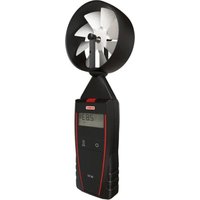
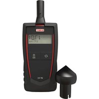
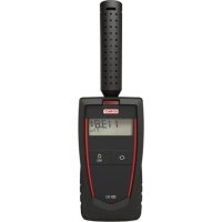
The Si-C320 is a transmitter that can measure simultaneous parameters including differential pressure, temperature (Pt100 and thermocouple), hygrometry, air quality (CO / CO_2 / VOC) , air velocity, airflow, air change rate...
- Operating temperature: -10 to 50^ (14 to 122^ )
Protection: IP66, resistant to VHP
Storage temperature: -10 to 70^ (14 to 158^ )
3. Directive 2014/53/EU
Hereby, Sauermann Industrie SAS declares that the radio equipment type Si-C320 is in compliance with Directive 2014/53/EU. The full text of the EU declaration of conformity is available at the following internet address: sauermanngroup.com
4. Mounting
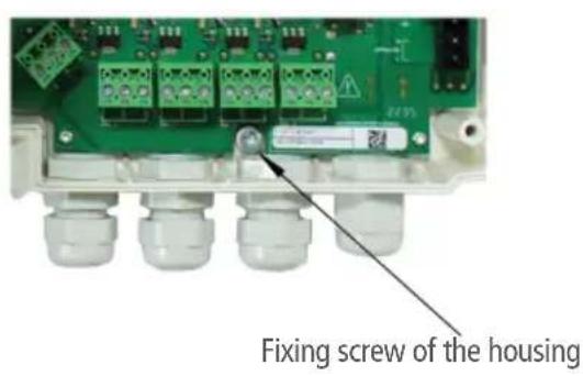
To install the transmitter on a wall, fix the stainless steel plate to the wall (drilling: 08mm , screws and wall-plugs supplied). Insert the transmitter on the plate (see A on the drawing below) by aligning it at 30^ . Rotate the housing in clockwise direction until you heard a "click" which confirms that the transmitter is correctly installed. Open the housing, lock the clamping system of the housing on the plate with the screw (see photo below). To remove the transmitter from the fixing plate, do not forget to remove this screw.
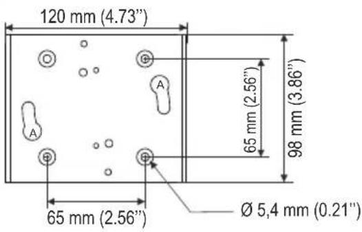
316L stainless steel plate
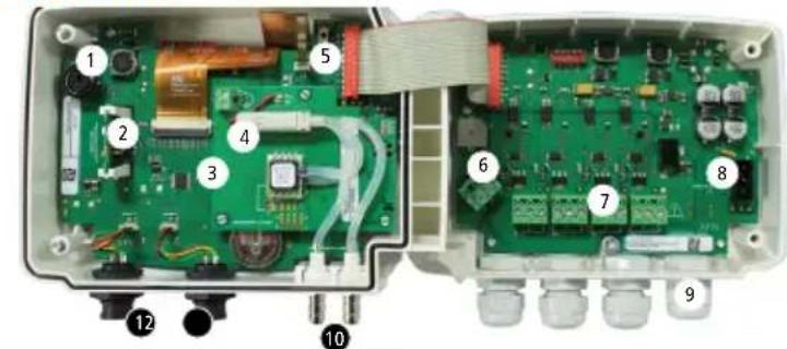
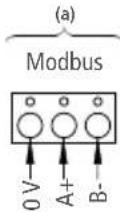
5. Connections
(b)
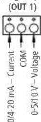
Analog output 1
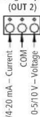
Analog output 2
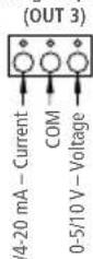
Analog output 3
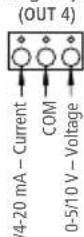
Analog output 4
- Connection for PC software
- Wireless module (optional)
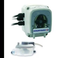
- Pressure module (optional)
- Solenoid valve
- Autozero
- RS 485 connection (a)
-
Analog outputs (b)
-
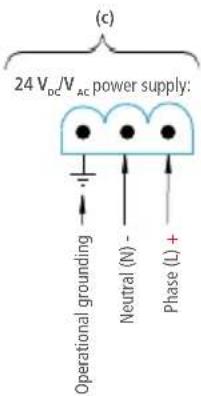
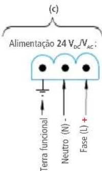
Power supply terminal block (c)
- Cable glands
- Pressure connectors (delivered on models with Si-PRO-DP pressure modules)
- Probe 1 connection
- Probe 2 connection
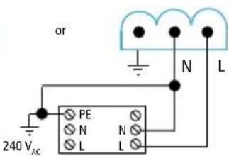
6. Electrical connections as per NFC15-100 standard

This connection must be made by a formed and qualified technician. Whilst making the connection, the transmitter must not be energized. The presence of a switch or a circuit breaker upstream the device is compulsory.
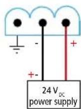
For 24V_DC models:
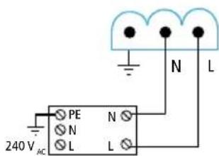
For 24V_AC models using power supply converters:
24 V power supply Class II
24 VAC power supply
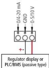
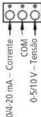
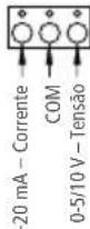
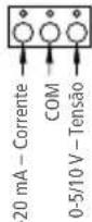
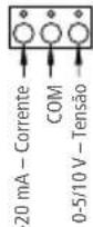
0/4-20 mA current output connection:
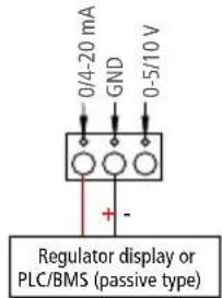
- 0-5/10 V voltage output connection:
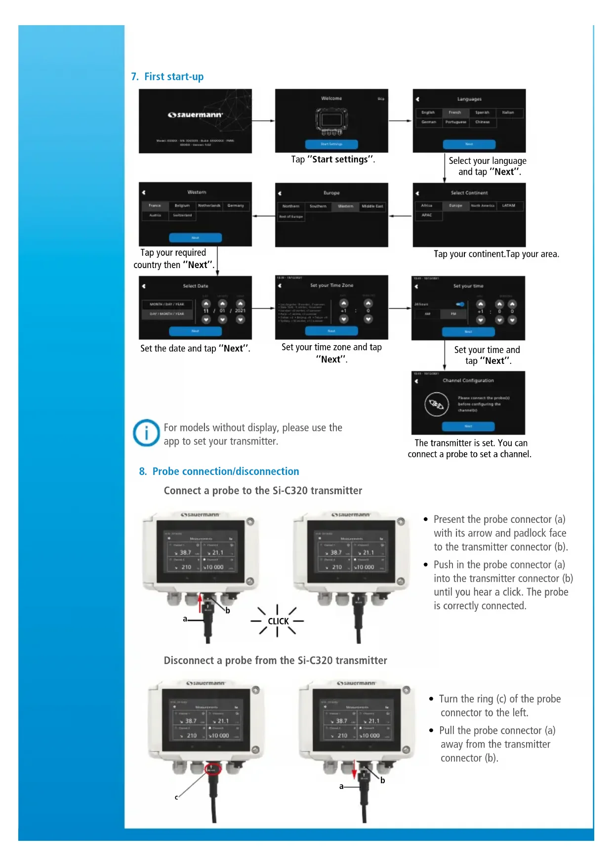
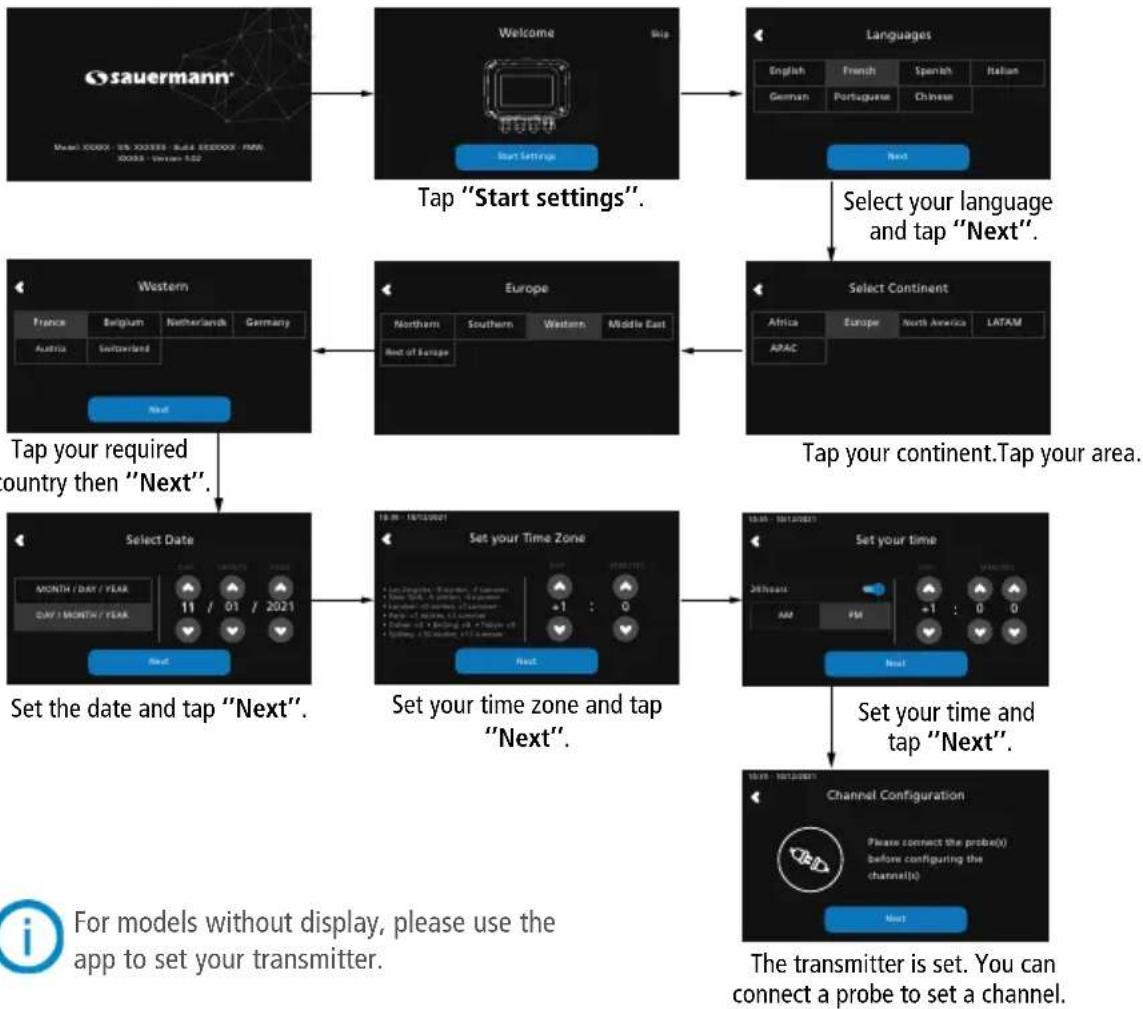
7. First start-up
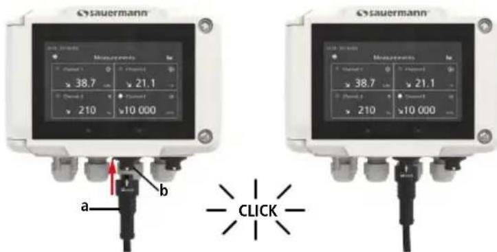
8. Probe connection/disconnection
Connect a probe to the Si-C320 transmitter
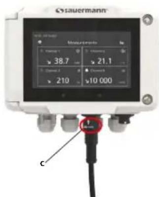
Disconnect a probe from the Si-C320 transmitter
Present the probe connector (a) with its arrow and padlock face to the transmitter connector (b).
- Push in the probe connector (a) into the transmitter connector (b) until you hear a click. The probe is correctly connected.
- Turn the ring (c) of the probe connector to the left.
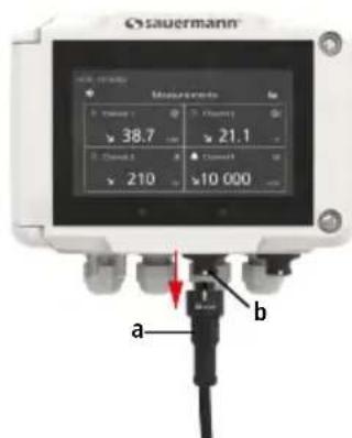
- Pull the probe connector (a) away from the transmitter connector (b).
9. Set a channel
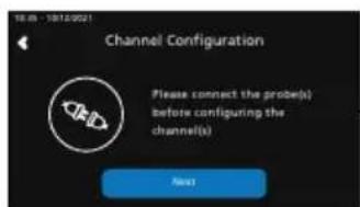
Connect a probe to set a channel and tap "Next".

The list of available channel is displayed.
Tap the required channel.

Tap "PROBE 1", "PROBE 2" or "MODULE". Parameters to set are now available.

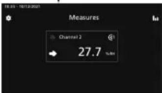
Channel 2 is configured. Tap next to configure outputs.
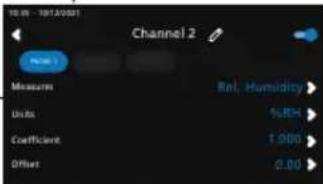
Set the parameters according to your needs then tap the back arrow on the top left.

For models without display, please use the app to set your channel.
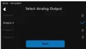
10. Set an output
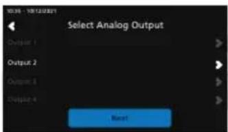
Tap the output to set corresponding to the previously configured channel.
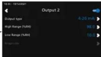
Activate the output taping Set the output type and high and low range values then tap the back arrow on the top left.
Tap "Next" to display measures.

For models without display, please use the app to set your output.
11. Maintenance
Please avoid any aggressive solvents. Please protect the transmitter and its probes from any cleaning product containing formalin, that may be used for cleaning rooms or ducts.
12. Precautions for use
Please always use the device in accordance with its intended use and within parameters described in the user manual in order not to compromise the protection ensured by the device.
Français
Guide rapide
Saida analogica 1 (OUT 1)
Saïda análogica 2 (OUT 2)
Saida analogica 3 (OUT 3)
Saïda anàlogica 4 (OUT 4)
Make the most of your device's capabilities by downloading the app
Access all documentation about the device.
Use our Customer service portal to contact us