VDV Scout Pro 3 - Measuring equipment Klein Tools - Free user manual and instructions
Find the device manual for free VDV Scout Pro 3 Klein Tools in PDF.

User questions about VDV Scout Pro 3 Klein Tools
0 question about this device. Answer the ones you know or ask your own.
Ask a new question about this device
Download the instructions for your Measuring equipment in PDF format for free! Find your manual VDV Scout Pro 3 - Klein Tools and take your electronic device back in hand. On this page are published all the documents necessary for the use of your device. VDV Scout Pro 3 by Klein Tools.
USER MANUAL VDV Scout Pro 3 Klein Tools
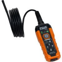
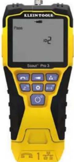
The Klein Tools VDV Scout™ Pro 3 is a portable voice-data-video cable tester. It tests and troubleshoots RJ11, RJ12, RJ45 and F-connector terminated cables, and provides tone generation for cable tracing. The VDV Scout™ Pro 3 also measures cable length, tests for shield, performs hub blink testing and traces up to 19 locations (up to 5 locations with the included remotes, additional remotes are available separately).
• Dimensions: 6.5" x 3.0" x 1.6" (16.5 x 7.6 x 4.1 cm)
• Weight: 11 oz. (312 g) with battery and remote
- Operating Temperature: 32° to 122 °F (0° to 50 °C)
• Storage Temperature: -4° to 140 °F (-20° to 60 °C)
• Humidity: 10% to 90%, non-condensing
- Maximum Voltage (between any two connector pins without damage):
- RJ Jack: 66V DC or 55V AC
- F-Connector: 66V DC or 55V AC
- Battery Life (9V alkaline):
- Standby: 4 years
- Active: 50 hours (without backlight)
- Cable Types: Shielded or unshielded; Cat7a, Cat7, Cat6a, Cat6, Cat5e, Cat3, Coaxial
• Length Measurement Method: Capacitance
• Length Measurement Range:
1.5' to 1999' (0.5 m to 610 m) with 15 pF/ft
• Length Accuracy: (5% ft) or (5% m)
• Length Constant Range:
10 pF/ft to 40 pF/ft (33 pF/m to 132 pF/m)
! WARNINGS
To ensure the safe operation and service of the tester, please follow these instructions. Failure to observe these warnings can result in severe injury or death.
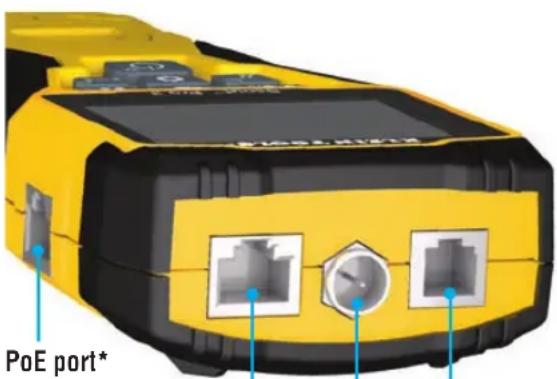
- The PoE jack, located on the right side of the Scout™ Pro 3 is the only jack designed for PoE energised cables. Connecting AC energised cables to any port may damage it and pose a safety hazard to the user.
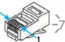
- Improperly terminated RJ plugs have the potential to damage the jacks on the VDV Scout™ Pro 3. Visually inspect an RJ plug before inserting it into the tester. The contacts should always be recessed into the plastic housing of the plug. Plugging 6-position plugs into the 8-position jack on the tester has the potential to damage the outer-most contacts of the jack, unless the plug is specifically designed for that purpose.
| SYMBOLS ON THE TESTER | |||
| Warning or Caution Do NOT use on energised circuits. | |||
| Always wear approved eye protection. Read the instructions | |||
| CE | Conformité Européenne. Conforms with European Economic Area directives. | ||
| This symbol indicates that the equipment and its accessories shall be subject to separate collection and correct disposal. | |||
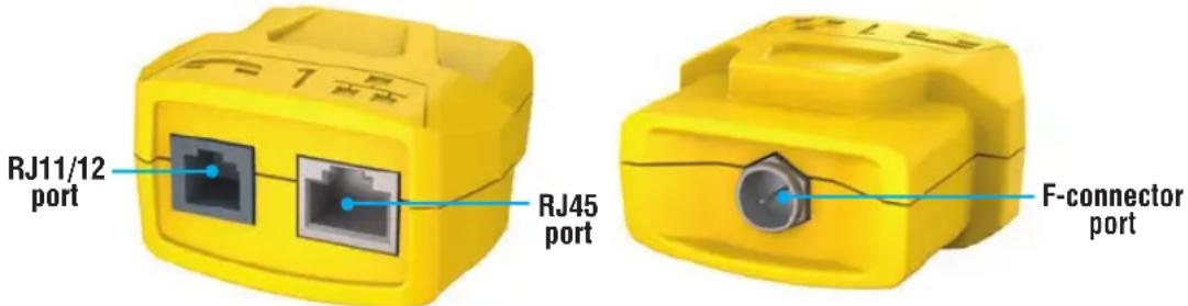
PORTS AND REMOTES OVERVIEW
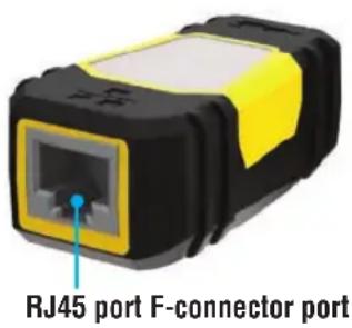
RJ45 Port: Data cable, Ethernet cable, Cat5e, Cat6, Cat6a, Cat7, Cat7a.
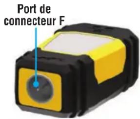
F-Connector Port: Video cable, coaxial cable, RG6/RG6Q cable, RG59 cable.
RJ11/12 Port: Voice cable, POTS (plain old televoice service) cable, 4-wire cable, 6-wire cable, 2 twisted-pair cables, 3 twisted-pair cables, Cat3.
VDV SCOUT™ PRO 3 TESTER LOCATION ID REMOTES
F-connector port
Use for cable location identification mapping. Set Nos. 1–5 included with VDV500-851, set Nos. 1–18 included with VDV501-852 and sold separately.
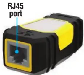
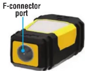
LanMap™
Location ID Remote**
VDV526-055
RJ45 connector
CoaxMap™
Location ID Remote**
VDV512-056
F-connector
**Cannot be used to perform wire map or cable length tests.
CONNECTORS
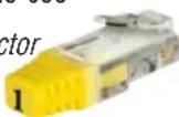
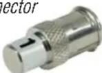
RJ11/12 port*RJ45 port* Barrel Connector
VDV814-609
Female-to-female F-connector Use with F-connector port
*The RJ jacks share internal connections, so only one RJ cable can be connected at a time for accurate cable test results. However, an RJ cable and a coax cable may be connected at the same time. In ID mode, all connectors on the VDV Scout ^TM Pro 3 may be connected at the same time.
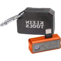
SELF-STORING TEST + MAP™ ID REMOTE (VDV501-210)
Use for cable location identification mapping and/or continuity testing. Self-storing remotes display on tester as Remote ID No. 1. Included with all VDV Scout™ Pro 3 models.
TEST + MAP™ ID REMOTES (VDV501-2## SERIES)
Use for cable location identification mapping and continuity testing. Remotes display on tester as Remote ID Nos. 1-12. Set Nos. 2–6 included with VDV500-853 and sold separately, set Nos. 7–12 sold separately, individual remote Nos. 1–12 each sold separately.
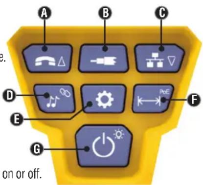
KEYPAD FUNCTION
QUICK REFERENCE
- VOICE / UP BUTTON A: Performs wiremap test on RJ11/RJ12 terminated cable, toggles selection upward in other modes.
• VIDEO BUTTON B: Performs continuity test on F-terminated coax cable. - DATA / DOWN BUTTON: Performs wiremap test on RJ45 terminated cable, toggles selection downward in other modes.
- TONE / HUB BLINK BUTTON D: Cycles through available tone cadences, initiates Hub Blink.
- SETTINGS BUTTON E: Selects feet or metres, enters Length Constant Edit mode.
- LENGTH / PoE BUTTON F: Measures cable length, initiates PoE test.
- POWER / BACKLIGHT BUTTON G: Turns unit on or off, turns backlight on or off.
IN DETAIL
- VOICE / UP BUTTON A: Short Press: Initiates wiremap test on RJ11/RJ12 terminated cable. When in Tone or Length Test mode, the first short press selects Voice mode, while repeated short presses selects wires or pairs of wires. Long press: Turns Loop mode on or off. When in Tone or Length Test mode, returns to the home screen. When in Settings mode, changes UOM from feet to metres, or increases the length contant value.
- VIDEO BUTTON B: Short Press: Initiates continuity test on an F-terminated coax cable. When in Tone or Length Test mode, a short press selects Video mode. Long Press: Turns Loop mode on or off. When in Tone or Length Test mode, returns to the home screen.
- DATA / DOWN BUTTON C:
Short Press: Initiates wiremap test on RJ45 terminated cable. When in Tone or Length Test mode, first short press selects Data mode, while repeated short presses select wires or pairs of wires. Long Press: Turns Loop mode on or off. When in Tone or Length Test mode, returns to the home screen. When in Settings mode, changes UOM from feet to metres, or increases the length contant value.
- TONE / HUB BLINK BUTTON D: Short Press: Repeated short presses will toggle through the available tone cadences. Long Press: Initiates Hub Blink. NOTE: DO NOT attempt to use Hub Blink function when connected to a Power over Ethernet (PoE) active port.
- SETTINGS BUTTON E: Short Press: Enters Length Constant edit mode (use the UP A and DOWN C buttons to adjust the value). Default for Length Constant mode is the wire pair of Pins 1 and 2 of data/RJ45 cable, and the wire pair of Pins 3 and 4 of voice/phone cable. See the LENGTH CONSTANT section for more details. Second Short Press: Displays option of feet or metres (use the UP A and DOWN C buttons to change). See the LENGTH MEASUREMENT section for details. Long Press: Exits Settings mode and returns to the home screen.
- LENGTH / PoE BUTTON F: Short Press: Initiates cable length test. Test will default to a cable connected to the RJ45 port. By default, the test will initiate on the first wire with no faults found. See the LENGTH MEASUREMENT and LENGTH CONSTANT sections for more details. Long Press: Initiates PoE test.
- POWER / BACKLIGHT BUTTON G: Short Press: First short press turns the unit on, repeated short presses will turn the backlight on and off. Press the power button a second time to turn the LCD backlight on or off. Long Press: Turns unit off. NOTE: Unit will automatically power off after 5 minutes of inactivity, or after 60 minutes when in Tone mode.
DISPLAY
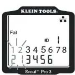
- MODE: The top line of the display shows what cable type is being tested; voice (RJ11/RJ12) ①, video (F-terminated coax) ③ or data (RJ45) ⑤, and if Hub Blink mode ④ or Tone mode ② is activated.
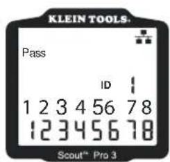
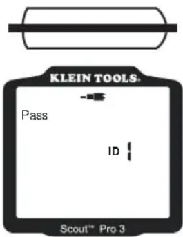
- PASS/SPECIAL CABLES: 'Pass' 6 will be displayed if the cable is a properly wired 4-pair T568A/B data cable, a 3-pair one-to-one wired voice cable or a video cable with no faults. In addition, 'X-over' 7 illuminates if a properly wired cross-over (uplink) cable is recognised, or 'Rev' 8 illuminates if the cable is a properly wired reverse-pinned voice cable. The wire map will show actual pin connections.
'Shielded' ⑨ illuminates when a shielded data cable is properly connected at both ends. It will be flashing if there is a short to a wire in the cable along with that pin number and the 'Short' ⑪ indicator.
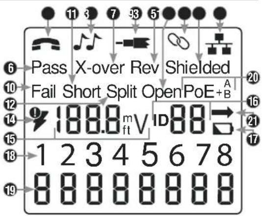
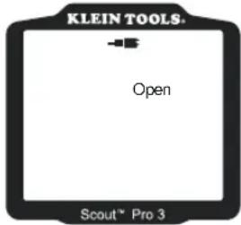
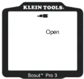
- CABLE FAULTS: 'Fail' 10 will illuminate only if the cable is not wired to one of the cabling standards. 'Short' (two wires making conductive contact) 11, 'Split' (wire pairs not maintained as pairs when terminated) 12, 'Open' (wires not making connection at both ends of the cable) 13, or a combination of these will also illuminate to indicate the type of fault(s) detected. See WIRING AND DISPLAY EXAMPLES section for wire standards and failure modes.
- VOLTAGE CHECK: A check for voltage on the RJ45 terminated data cable is performed before each test, and if found, no test is run. If a voltage is detected on any of the tester connectors, the lightning bolt icon 14 illuminates. The tester should be disconnected immediately from the source of the voltage.
- MEASUREMENT: 15 Length mode: Length of cable run in feet or metres. PoE mode: Voltage.
- LOCATION ID: 16 The remote ID number will display here.
- BATTERY STATUS: The battery low icon illuminates when the battery is nearing depletion. The icon will illuminate when the battery needs to be replaced. Results may be unreliable at this point.
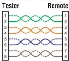
- TESTER-END WIRE MAP: 18 Displays the pins on the tester end of the cable in order. These pins are mapped to the pins on the remote-end shown directly below them on the LCD
- REMOTE-END WIRE MAP: 19 Displays the corresponding pin on the remote-end. Dashed lines on this row indicate shorted pins. No pin numbers displayed on this row line are open pairs.
- PoE INDICATORS: 20 Indicate PoE configuration. See the chart on page 10 for details.
- PoE ERROR INDICATOR: 21 Indicates no PoE detected when the test is initiated.
OPERATING INSTRUCTIONS
LENGTH MEASUREMENT: The VDV Scout™ Pro 3 uses the capacitive properties of a cable to measure its length. One end of the cable should be connected to the corresponding port on the top of the tester. The other end should be left disconnected or attached to the self-storing remote.
LENGTH CONSTANT: The length constant refers to the electrical characteristic of a cable used to characterise its length. Every cable has an associated length constant in units of picofarads per foot (pF/ft). Setting the length constant on the tester is important for obtaining an accurate cable length measurement from the VDV Scout™ Pro
- The default length constants are as follows: Voice: 17.0 pF/ft Data: 15.0 pF/ft Video: 15.0 pF/ft
The length constant can sometimes be provided by the manufacturer of the cable (see DISPLAYING/EDITING LENGTH CONSTANT section). You may have to determine the length constant yourself (see DETERMINING AN UNKNOWN LENGTH CONSTANT section). Length constants can range from 10 pF/ft to 40 pF/ft.
Measurement accuracy is dependent on how close the tester can be set to the length constant of the cable being measured and the consistency of the cable along its length.
The length constant can vary from cable to cable, even if it is of the same type, produced by the same manufacturer. It can also vary over the length of one cable, because the length constant is dependent on the physical properties of the cable, which may not be consistent throughout the entire cable. The change in wire-pair spacing through the cable can vary the length constant along the length of the cable.
When setting the length constant using a length of cable, the cable should be at least 50^ (15.2 m) long. This will yield a ±5% uncertainty (1 in 50) in the length constant accuracy. A longer cable reduces this uncertainty.
MEASURING LENGTH - VOICE OR DATA CABLES:
-
Press the Power button G to turn the tester on.
-
Connect one end of the cable to the appropriate port: RJ45 port (if testing data cable) or RJ12 port (if testing voice cable), located at the top of the main tester body. Leave the other end of the cable unterminated.
-
Press the Length button F to enter Length mode.
-
Press the Data button C or Voice button A, depending on the cable being tested, to begin the test.
-
Press the Data button C repeatedly to select the pair of wires that should be measured. The first functional pair is chosen by default.
-
Read the length measurement as shown.
MEASURING LENGTH - COAX CABLES:
-
Press the Power button Ⓖ to turn the tester on.
-
Connect one end of the cable to the F-connector port located at the top of the main tester body. Leave the other end of the cable unterminated.
-
Press the Length button F to enter Length mode.
-
Press the Video button Ⓑ to begin the test.
-
Read the length measurement as shown.
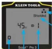
Cable Type
Indicates Shielded cable
Test Running Continuously Remote ID No. (if terminated)
Measured Length = 45 ft.
NOTE: A voice or data cable under test can be unterminated (open) or terminated by an RJ45 ID remote. If it is terminated by the self-storing remote, the reading will be 1' or 2' greater than the actual measurement. In this case, subtract 1' or 2' from the reading to obtain the actual measurement. The coax cable under test may be left unterminated.
OPERATING INSTRUCTIONS
DISPLAYING/EDITING LENGTH CONSTANT:
Follow these instructions to set the length constant based on a known value (for example, as given by the cable manufacturer). The VDV Scout™ Pro 3 stores a separate length constant for each of the three cable types (voice, data and video).
- Press the Power button G to turn the tester on.
- Press the Settings button E.
- Select the cable type by pressing the Voice button A, the Coax button B or the Data button C.
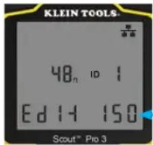
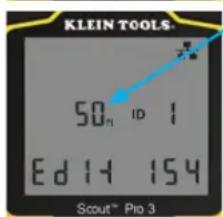
The length constant will be displayed with the word 'EDIT'. Use the UP A and DOWN C buttons to increase or decrease the Length Constant value in units of 0.1 pF/ft to the desired value. The decimal is not displayed, so for example, '154' on the display means that the Length Constant is 15.4 pF/ft. Length Constants are displayed in pF/ft or pF/m, depending on the selected unit of measurement mode.
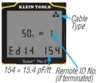
NOTE: The Length Constant can only be edited in the pF/ft mode. It is not editable in the pF/m mode.
NOTE: The Default for Length Constant edit for the Data cable is the wire pair of Pins 1 and 2. If you wish to set the Cable Length constant on wire pairs other than Pins 1 and 2 of a data/RJ45 cable, follow Steps 1 through 3 above. Press the Length button F. Press the Data button C repeatedly until the pair you wish to edit is displayed. Press the Edit button E again, and you will be editing the wire pair you just selected.
NOTE: The Default for Length Constant edit for the Voice cable is the wire pair of Pins 3 and 4 of a voice cable. If you wish to set the Cable Length constant on Wire pairs other than pins 3 and 4 of a voice cable, follow Steps 1 through 3 above. Press the Length button F. Press the Voice button A repeatedly until the pair you wish to edit is displayed. Press the Edit button E again, and you will be editing the wire pair you just selected.
DETERMINING AN UNKNOWN LENGTH CONSTANT:
Follow these instructions to set the Length Constant based on a sample cable of known length. For the best accuracy, the sample cable should be 50 ft or longer. This example will use 50 ft.
- Acquire a known length of cable at least 50 ft in length (50 ft in this example) of the same type that you would like to measure.
- Press the Power button Ⓖ to turn tester on.
- Follow the procedure in the MEASURING LENGTH section(s) to set up the correct type of cable.
- Press the Settings button E to enter Edit mode.
- Use the Up A and Down C buttons to increase or decrease the Length Constant, in units of 0.1 pF. Continue to adjust the Length Constant until the Length Measurement displays the correct known length measured earlier.
You may now measure other unknown lengths of cable using this measured length constant.
Adjust the Length Constant up or down until the Length Measurement displays as the known length of the sample cable (50 ft in this example)
CHANGING THE UNIT OF MEASUREMENT:
- Press the Power button G to turn tester on.
- Press the Settings button E twice; 'ft' or 'm' will be displayed.
- Use the Up A and Down C buttons to change between feet (ft) and metres (m).
NOTE: Feet unit readings have no decimal place and are displayed as '0 ft'. Metre unit readings have one decimal place and are displayed as '0.0 m'.
TESTING CONTINUITY:
Faults: When testing for continuity of a cable, you are checking that all conductors within a cable are connected properly from one end to the other. Usually, faults occur when terminations on each side are not connected (an 'open'), or when adjacent conductors are accidentally connected (a 'short').
Miswires/split pairs: 8-wire data cables can have an additional set of errors. A miswire simply means that the pin on one side of the cable is not connected to the identical pin on the other side of the cable (for example, Pin 2 on one side is connected to Pin 6 on the other side). Certain pairs of conductors are required to be twisted together from end point to end point. These errors are called split pairs and can be present in cables that aren't miswired.
OPERATING INSTRUCTIONS
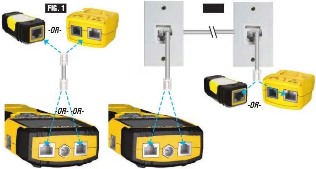
TESTING CONTINUITY ON TERMINATED OR INSTALLED RJ45/RJ11/RJ12 CABLE (FIG. 1, FIG. 2):
- Connect one end of the cable under test to the RJ45 port (if testing a data cable) or the RJ11/RJ12 port (if testing a voice cable), located at the top of the main tester body. If testing a wall port, connect a known good patch cable from the wall plate to the appropriate port at the top of the main tester body.
- Connect the other end of the cable under test to the corresponding port on the testing remote. If testing a wall port, connect a known good patch cable from the wall port to the appropriate port on the testing remote. NOTE: Location-only ID remotes cannot be used.
- Press the Data button C or the Voice button A on the keypad to begin the test.
- Interpret the results of the test using the WIRING AND DISPLAY EXAMPLES section.
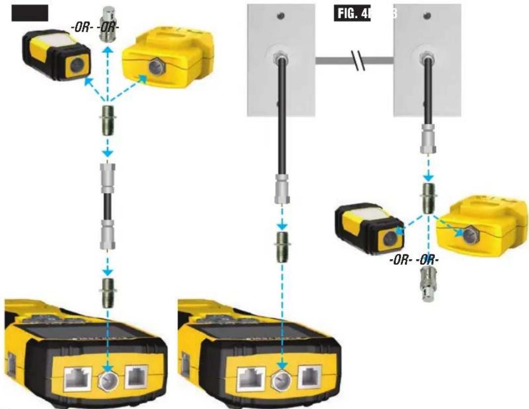
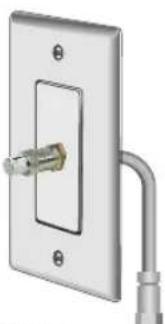
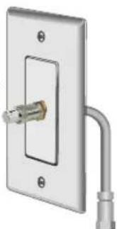
TESTING CONTINUITY ON TERMINATED OR INSTALLED COAX CABLE (FIG. 3, FIG. 4):
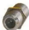
- Attach female-to-female Barrel Connector to the F-connector port on the top of the tester.
- Connect one end of the cable to be tested to this adapter.
- If testing a terminated coax cable, attach a second Barrel Connector to the other end of the cable under test. NOTE: This step is not necessary if testing an installed coax cable, or a cable attached to a wall plate.
- Connect either a numbered CoaxMap™ Location ID Remote or one of the Test + Map™ ID Remotes to the Barrel Connector.
- Press the Video button Ⓑ to begin the test.
- Interpret the results of the test using the WIRING AND DISPLAY EXAMPLES section.
OPERATING INSTRUCTIONS
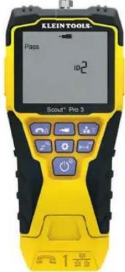
CABLE IDENTIFICATION – DATA AND VOICE CABLES:
It is often necessary to identify cables that branch out from the wiring closet. The VDV Scout™ Pro 3 can assist in two ways:
The first and most convenient way to identify installed cables is by using location ID remotes. Using location ID remotes, you can trace up to 19 drop locations with one trip to the wiring closet or router. Identification with ID remotes is done digitally and does not rely on any manual tracing.
The second way to identify cables is by using the VDV Scout™ Pro 3's built-in analog tone generator. The tester will place a low-frequency voltage on the cable. By using an analog tone probe (Klein Tools VDV500-123, sold separately), a cable can be identified by the tone it is carrying. This technique only allows one cable to be traced per tone generator, but has additional benefits like the ability to trace unterminated cables of non-standard types.
- LanMap™ Location ID Remotes identify location only.
- CoaxMap™ Location ID Remotes identify location only.
- Test+Map™ ID Remotes identify location, and perform wire map and length tests.
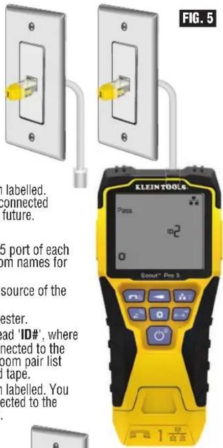
IDENTIFYING INSTALLED RJ45 CABLE (FIG. 5):
- Insert a numbered LanMap™ Location ID Remote into the RJ45 port of each room that needs to be identified. Write down numbers and room names for later reference.
- Take the VDV Scout™ Pro 3 to the wiring closet or router (the source of the internet connection).
- Connect an unknown cable to the RJ45 port on the top of the tester.
- Press the Data button Ⓐ to begin the ID test. The LCD will read 'ID#', where '#' is the ID number of the LanMap™ Location ID Remote connected to the other side of the cable. Compare this number to the number/room pair list you made in Step 1 and mark the cable with a piece of labelled tape.
- Repeat Steps 3 and 4 for each unknown cable until all have been labelled. You can use these labels to determine which rooms should be connected to the router, or to troubleshoot intermittent connections in the future.
IDENTIFYING INSTALLED VOICE CABLE (FIG. 5):
- Insert a numbered LanMap™ Location ID Remote into the RJ45 port of each room that needs to be identified. Write down numbers and room names for later reference.
- Take the VDV Scout™ Pro 3 to the wiring closet or router (the source of the internet connection).
- Connect an unknown cable to the RJ45 port on the top of the tester.
- Press the Voice button A to begin the ID test. The LCD will read 'ID#', where '#' is the ID number of the LanMap™ Location ID Remote connected to the other side of the cable. Compare this number to the number/room pair list you made in Step 1 and mark the cable with a piece of labelled tape.
- Repeat Steps 3 and 4 for each unknown cable until all have been labelled. You can use these labels to determine which rooms should be connected to the router, or to troubleshoot intermittent connections in the future.
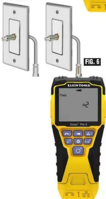
IDENTIFYING INSTALLED COAX CABLE (FIG. 6):
- Insert a numbered CoaxMap™ Location ID Remote into the F-connector port of each room that needs to be identified. Write down numbers and room names for later reference.
- Take the VDV Scout™ Pro 3 to the wiring closet or cable splitter (the source of the cable connection).
- Attach female-to-female Barrel Connector to the F-connector port on the top of the tester, then connect an unknown cable to the Barrel Connector.
- Press the Video button B to begin the ID test. The LCD will read 'ID#', where '#' is the ID number of the CoaxMap™ Location ID Remote connected to the other side of the cable. Compare this number to the number/room pair list you made in Step 1 and mark the cable with a piece of labelled tape.
- Repeat Steps 3 and 4 for each unknown cable until all have been labelled.
OPERATING INSTRUCTIONS
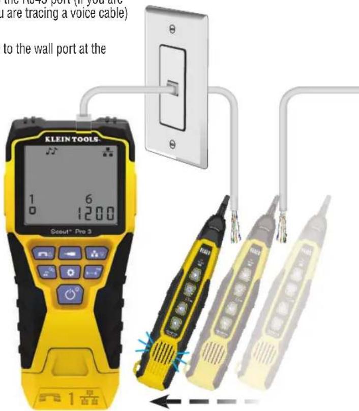
TONE TRACING ON INSTALLED RJ45/RJ11/RJ12 CABLE (FIG. 7):
- Connect a known working patch cable to the RJ45 port (if you are tracing a Data cable) or RJ12 port (if you are tracing a voice cable) at the top of the tester.
- Connect the other end of the patch cable to the wall port at the satellite location of the cable under test.
- Short press the Tone button D to initialise the tone generation. Press the Tone button D repeatedly to cycle through the available tones, from a steady low or high tone, to a warbling slow or fast tone. For voice toning, repeatedly pressing the Voice/Up A button will change the pins or pairs of pins the tone is carried on. For data toning, repeatedly pressing the Data/Down C button will change the pins or pairs of pins on which the tone is carried.
- Use an analog tracing probe (Klein Tools VDV500-123 recommended, sold separately) to determine the wire or wires on which the tone is being transmitted (see the Tone Probe Instruction Manual for details). The tone will be loudest at the cable to which the VDV Scout™ Pro 3 is connected. Mark the cable with a label.
- Repeat Steps 2-6 for each unknown cable location.
FIG. 7
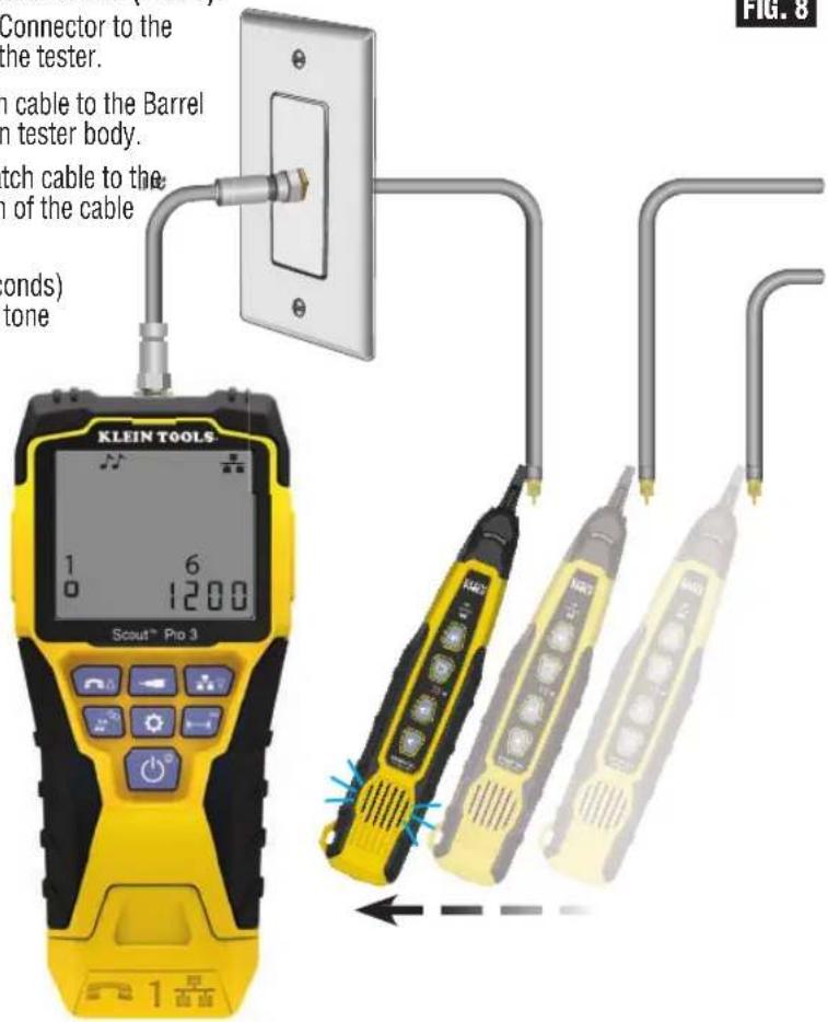
TONE TRACING ON INSTALLED COAX CABLE (FIG. 8):
- Attach female-to-female Barrel Connector to the F-connector port on the top of the tester.
- Connect a known working patch cable to the Barrel connector at the top of the main tester body.
- Connect the other end of the patch cable to the wall port at the satellite location of the cable under test.
- Short Press (for less than 2 seconds) the Tone button D to initialise tone generation. Press the Tone button D repeatedly to cycle through the available tones. Value (in ohms) of the tone being transmitted will display on the bottom row.
- Use an analog tracing probe to determine the wire on which the tone is being transmitted (see the Tone Probe Instruction Manual for details). The tone will be loudest at the cable to which the VDV Scout™ Pro 3 is connected. Mark the cable with a label.
- Repeat Steps 2-6 for each room that has cable installed.
FIG. 8
OPERATING INSTRUCTIONS
TESTING CONTINUITY & CABLE IDENTIFICATION SIMULTANEOUSLY:
The VDV Scout™ Pro 3 has the capability of simultaneously testing continuity and providing cable location identification for up to twelve locations with Test + Map™ ID Remotes (sold separately). The VDV Scout™ Pro 3 series testers come with the Self-Storing Test + Map™ ID Remote No. 1. Test + Map™ ID Remotes No. 2 through No. 6 are included in some kits (VDV501-853, VDV770-850), Test + Map™ ID Remotes No. 7 through No. 12 are sold separately in the VDV Scout™ Pro 3 Test + Map™ ID Remote Kit (VDV770-851).
TESTING CONTINUITY & CABLE IDENTIFICATION SIMULTANEOUSLY - INSTALLED RJ45/RJ11/RJ12 CABLE
- Attach a numbered Test + Map™ ID Remote to the RJ45/RJ12 port of each room that needs to be identified using a known good patch cable‡. Write down the number of the remote and of the room number/description in which it is placed, for comparing/identifying the cables later.
- Take the VDV Scout™ Pro 3 to the distribution point (often a wiring closet, switch or router at the other end of the cable being tested).
- Connect an unknown cable to the RJ45 port on the top of the tester.
- Press the Data button C or Voice button A on the keypad to begin the test on the data or voice cable, respectively. The LCD will display 'ID#', where '#' is the ID number of the Test + Map™ ID Remote connected to the other side of the cable.
- Compare this number to the remote number/room pair list you made in Step 1 and mark the cable with a piece of labelled tape, print a label or mark with permanent marker. The LCD will also display the results of the continuity test. These results should be interpreted using the WIRING AND DISPLAY EXAMPLES section.
- Repeat Steps 4 and 5 for each unknown cable until all cables have been labelled. You can use these labels to determine which rooms should be connected to the cable splitter, or to troubleshoot intermittent connections in the future.
NOTE: Only Klein Tools Universal RJ12 Jumper Cable (VDV726-125) or an approved equivalent should be used in the RJ45 jack of the Test + Map™ ID Remotes. Using a standard RJ11/12 patch cable in the RJ45 port on the tester could result in damaged contact pins.
TESTING CONTINUITY & CABLE IDENTIFICATION SIMULTANEOUSLY - INSTALLED COAX CABLE
- Attach a numbered Test + Map™ ID Remote to the F-connector port of each room. Write down the number of the remote and of the room number/description in which it is placed, for comparing/identifying the cables later.
- Take the VDV Scout™ Pro 3 to the distribution point (often a wiring closet, switch or router at the other end of the cable being tested).
- Connect an unknown cable to the Video port on top of the tester using a barrel connector.
- Press the Video button B on the keypad to begin the test on the coax cable. The LCD will display 'ID#' where '#' is the ID number of the Test + Map™ ID Remote connected to the other side of the cable.
- Compare this number to the remote number/room pair list that you made in step 1 and mark the cable with a piece of labelled tape, print a label or mark it with a permanent-ink pen. The LCD will also display the results of the continuity test. These results should be interpreted using the Wiring and Display Example section
- Repeat Steps 4 and 5 for each unknown cable until all have been labelled. You can use these labels to determine which rooms should be connected to the cable splitter, or to troubleshoot intermittent connections in the future.
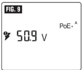
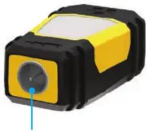
TESTING POWER OVER ETHERNET (PoE) - (FIG. 9)
- Press the Power button Ⓖ to turn the tester on.
- Connect PoE powered Data (RJ45 terminated) cable to the PoE port on right side of tester.
- Long press the Length button F to initiate the PoE test.
- If power is present, the tester will display the Voltage icon (lightning bolt) 14, and the voltage from the PSE (Power Sourcing Equipment).
- PoE mode will be displayed 'PoE' or 'PoE+' (see 'IEEE Standard PoE Parameters' chart on the next page for details).
- PoE wiring configuration will be displayed: 'A', 'B' or 'AB'.
HUB BLINK FUNCTION
- Insert RJ45 terminated data cable into RJ45 port on top of tester, connect other end to equipment (hub, switch, router, etc.).
- Press the Power button Ⓖ to turn the tester on.
- Long press (> 1 second) the Tone D button.
- Signal will be transmitted from tester to equipment to illuminate the corresponding port's light.
POWER OVER ETHERNET (PoE) REFERENCE CHARTS
POWER OVER ETHERNET (PoE) REFERENCE CHARTS
| Pin at Source | TIA/EIA-568 T568B Termination | TIA/EIA-568 T568A Termination | 10/100 Mode B DC on Spares | 10/100 Mode A Mixed DC & Data | 1000 (1 GB) Mode B DC & Bi-Data | 1000 (1 GB) Mode A DC & Bi-Data | ||||
| Data Power Data | Power Data | Power Data | ||||||||
| 1 |  White/Orange White/Orange |  White/Green White/Green | Rx+ | - | Rx+ | DC+ | TxRx A+ | - | TxRx A+ | DC+ |
| 2 |  Orange Orange |  Verde Verde | Rx- | - | Rx- | DC+ | TxRx A- | - | TxRx A- | DC+ |
| 3 |  White/Green White/Green |  White/Orange White/Orange | Tx+ | - | Tx+ | DC- | TxRx B+ | - | TxRx B+ | DC- |
| 4 |  Blue Blue |  Blue Blue | - | DC+ | - | - | TxRx C+ | DC+ | TxRx C+ | - |
| 5 |  White/Blue White/Blue |  White/Blue White/Blue | - | DC+ | - | - | TxRx C- | DC+ | TxRx C- | - |
| 6 |  Green Green |  Orange Orange | Tx- | - | Tx- | DC- | TxRx B- | - | TxRx B- | DC- |
| 7 |  White/Brown White/Brown |  White/Brown White/Brown | - | DC- | - | - | TxRx D+ | DC- | TxRx D+ | - |
| 8 |  Brown Brown |  Brown Brown | - | DC- | - | - | TxRx D- | DC- | TxRx D- | - |
| Property 802.3af (PoE) 802.3at (PoE+) | ||
| Power available at powered device (PD) | 12.95 W | 25.50 W |
| Maximum power delivered by powered device (PD) | 15.40 W | 30.00 W |
| Voltage range at powered device (PD) | 37.0 to 57 V | 42.5 to 57 V |
| Voltage range at powered device (PD) | 44.0 to 57 V | 50.0 to 57 V |
WIRE MAP AND DISPLAY EXAMPLES
NOTE: Test + Map remote must be used for wire map testing.
PROPERLY WIRED T568A UTP:

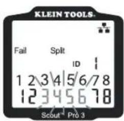
T568A SPLIT PAIRS:
T568A SHORT AND OPEN: T568A MISWIRE & UNRECOGNISED CONTINUITY:
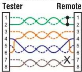
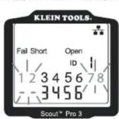
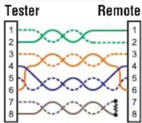
NOTE: An open fault or short fault takes precedence over miswires when the appropriate icon(s) illuminates. The Split icon illuminates if the cable wiring does not maintain the designated pairs, an AC signal fault.
8
8- = FLASHING
WIRE MAP AND DISPLAY EXAMPLES
COAX CABLE PROPERLY WIRED: COAX CABLE WITH AN OPEN:

COAX CABLE WITH A SHORT:
NOTE: An open fault will also occur when no remote is connected to the satellite end of a video/coax cable.

BATTERY REPLACEMENT
- Loosen screw ion battery cover with No. 2 Phillips screwdriver.
- Remove the battery door.
- Disconnect the battery cable and recycle the exhausted battery.
- Install a fresh 9-volt alkaline battery.
- Connect battery cable to the new battery, observing polarity, and place it into battery compartment.
- Replace battery door and secure with a screw, taking care not to over-tighten.
WARRANTY
Turn the instrument off and disconnect any cables. Clean the instrument using a damp cloth.
Do not use abrasive cleaners or solvents.
STORAGE
Remove the batteries when the instrument is not in use for a prolonged period of time. Do not expose to high temperatures or humidity. After a period of storage in extreme conditions exceeding the limits mentioned in the Specifications section, allow the instrument to return to normal operating conditions before using it.
DISPOSAL/RECYCLING
Do not place the equipment and its accessories into a domestic rubbish bin. Items must be properly disposed of in accordance with local regulations. Please see www.epa.gov or www.erecycle.org for additional information.
UPGRADE/REPLACEMENT REMOTES
TEST + MAP™ ID REMOTES (VDV501-2## SERIES)
Use for cable location identification mapping and continuity testing. Remotes display on tester as Remote ID Nos. 1-12 ^2 _2-6
natural_image
3D illustration of a yellow and black device with a blue pointer (no text or symbols)| REMOTE ID NO. | PART NO. |
| 1 VDV501-211 | |
| 2 VDV501-212 | |
| 3 VDV501-213 | |
| 4 VDV501-214 | |
| 5 VDV501-215 | |
| 6 VDV501-216 | |
| 7 VDV501-217 | |
| 8 VDV501-218 | |
| 9 VDV501-219 | |
| 10 VDV501-220 | |
| 11 VDV501-221 | |
| 12 VDV501-222 | |
| 2–6 VDV770-850 | |
| 7–12 VDV770-851 | |
CUSTOMER SERVICE
KLEIN TOOLS, INC.
450 Bond Street, Lincolnshire, IL 60069 1-800-553-4676
www.kleintools.com
DEUTSCH
natural_image
Close-up of a white electrical outlet with a yellow connector and a white cable (no text or symbols visible)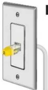
natural_image
Close-up of a white electrical switch with a yellow cable inserted, no text or symbols visible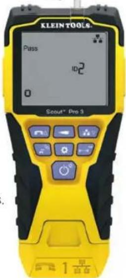
natural_image
Close-up of a metallic electrical outlet with a U-shaped pipe fitting attached (no text or symbols visible)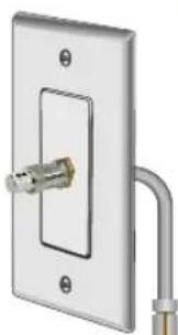
natural_image
Exterior view of a metallic electrical outlet with a U-shaped pipe fitting (no text or symbols)ABB.6
BETRIEBSANLEITUNG
TONORTUNG BEI VERLEGTEM RJ45-/RJ11-/RJ12-KABEL (ABB. 7):
natural_image
3D illustration of a black and yellow USB drive with a white connector (no text or symbols)natural_image
3D rendered image of a yellow and black device with a circular lens (no text or symbols visible)| ID-NR. DER REMOTE-EINHEIT | TEILE-NR. |
| 1 VDV501-211 | |
| 2 VDV501-212 | |
| 3 VDV501-213 | |
| 4 VDV501-214 | |
| 5 VDV501-215 | |
| 6 VDV501-216 | |
| 7 VDV501-217 | |
| 8 VDV501-218 | |
| 9 VDV501-219 | |
| 10 VDV501-220 | |
| 11 VDV501-221 | |
| 12 VDV501-222 | |
| 2-6 VDV770-850 | |
| 7-12 VDV770-851 |
KUNDENSERVICE
NetPeppers GmbH
Perchastr. 8e, 82319 Starnberg
+49-89-219097300
www.netpeppers.com
TEST DE CONTINUITÉ SUR CÂBLE COAXIAL TERMINÉ OU INSTALLÉ (FIG. 3, FIG. 4) :
INSTRUCTIONS D'UTILISATION
natural_image
Electrical outlet switch with a metallic connector and pipe fitting (no text or symbols visible)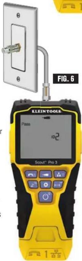
IDENTIFICATION D'UN CÂBLE COAXIAL INSTALLÉ (FIG. 6) :
FONCTION HUB BLINK (CLIGNOTEMENT DU CONCENTRATEUR)
natural_image
Two identical black and yellow USB flash drives with ports, shown from different angles (no text or symbols visible)natural_image
Close-up of a white electrical outlet with a yellow connector and metal fittings (no text or symbols visible)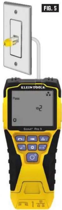
natural_image
Close-up of a white electrical outlet wall with a metallic connector and metal rod (no text or symbols visible)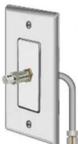
natural_image
Exterior view of a wall-mounted electrical outlet with a metallic connector and pipe fitting (no text or symbols)FIG. 6
INSTRUCCIONES DE USO
ANÁLISIS DE TONOS EN UN CABLE CON TERMINAL RJ45 / RJ11 / RJ12 INSTALADO (FIG. 7):
CABLE COAXIAL
CON UNA ABERTURA:

CABLE COAXIAL
CON UN CORTOCIRCUITO: