
EJS 750-L - Saw MATRIX - Free user manual and instructions
Find the device manual for free EJS 750-L MATRIX in PDF.

| Product type | Keyhole saw (jigsaw) |
| Brand | Matrix |
| Model | EJS 750-L |
| Power supply | Mains 230-240 V ~ 50 Hz |
| Power consumption | 750 W |
| Stroke rate | 0-3100 spm (variable) |
| Cutting depth wood | 80 mm |
| Cutting depth metal | 8 mm |
| Mitre cut | Up to 45° (left and right) |
| Protection class | II (double insulation) |
| Sound pressure level | 87.5 dB(A) |
| Sound power level | 98.5 dB(A) |
| Vibration (wood) | 6.617 m/s² (K=1.5 m/s²) |
| Vibration (sheet metal) | 7.191 m/s² (K=1.5 m/s²) |
| Main features | Variable speed, adjustable pendulum action, laser guide, parallel stop, dust extraction adapter, tool-free blade change, tilting base plate |
| Maintenance | Clean after use, check carbon brushes |
| Safety | Switch with lock-off, protective cover, safety stop |
| Spare parts | Saw blades, carbon brushes, base plate, parallel stop |
| Warranty | 24 months |
Frequently Asked Questions - EJS 750-L MATRIX
User questions about EJS 750-L MATRIX
0 question about this device. Answer the ones you know or ask your own.
Ask a new question about this device
Download the instructions for your Saw in PDF format for free! Find your manual EJS 750-L - MATRIX and take your electronic device back in hand. On this page are published all the documents necessary for the use of your device. EJS 750-L by MATRIX.
USER MANUAL EJS 750-L MATRIX
natural_image
Black-and-white photo of a power tool with visible brand label and certification marks (no readable text beyond branding)D
Translation of the original instructions
Jigsaw
NL
natural_image
Close-up of a sewing machine's mechanical component, showing clamping mechanism and base mount (no text or symbols visible)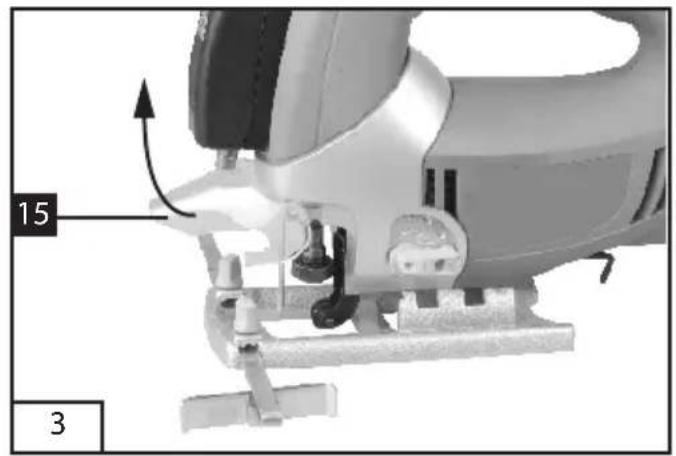
natural_image
Mechanical component diagram showing a lever mechanism with labeled parts (15 and 3), no readable text or symbols beyond labels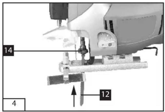
text_image
14 12 4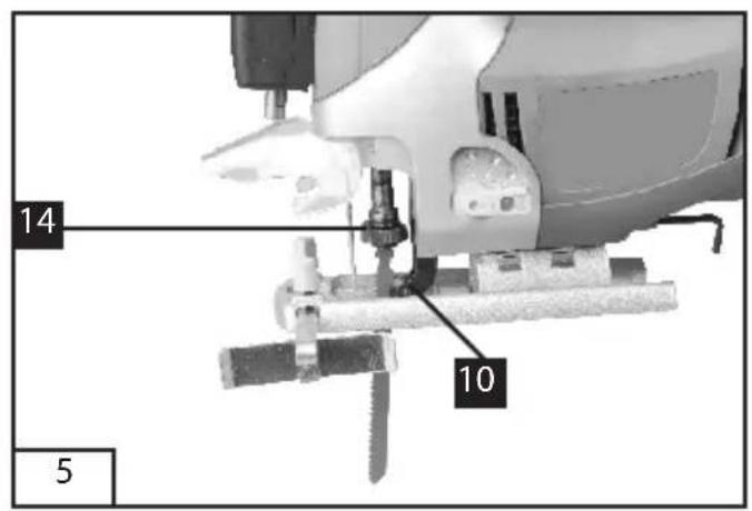
text_image
14 10 5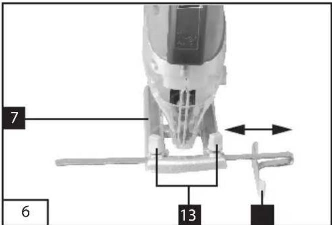
text_image
7 6 13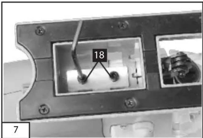
text_image
18 7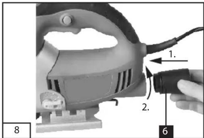
text_image
1. 2. 6 8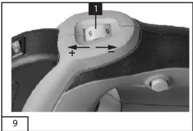
text_image
1 9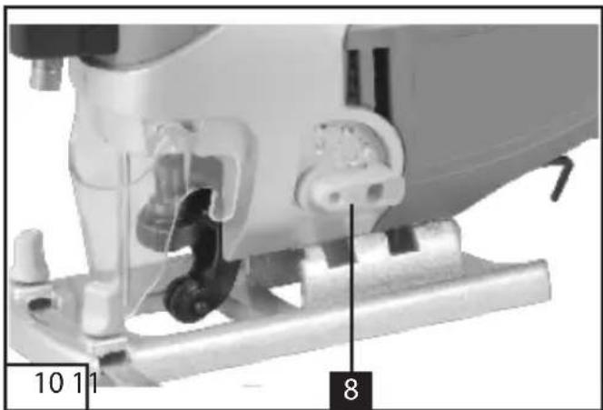
natural_image
Close-up of a sewing machine's mechanical component, showing stitching and adjustment parts (no text or symbols visible)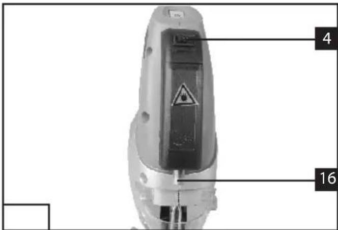
text_image
4 16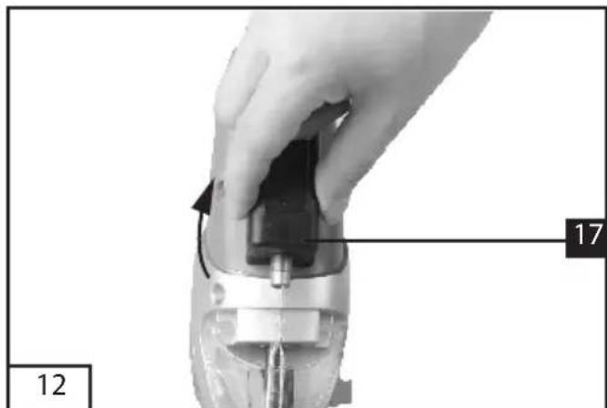
natural_image
Close-up of a hand holding a mechanical component with a numbered label (12 and 17) indicating part number, no readable text or symbols beyond labels.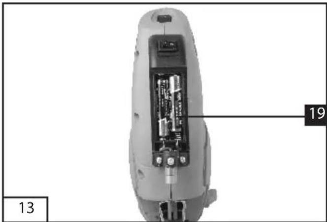
text_image
13 19Attention: Rayon laser
do not stare into beam
λ: 650 nm P<1 mW
Laser Klasse 2
Class 2 Laser Product
EN 60825-1:2007
The machine is intended for making separating cuts and cut-outs in wood, plastic, metal, ceramic plates and rubber while resting firmly on the workpiece. It is suitable for straight and curved cuts with mitre angles to 45^ . The saw blade recommendations are to be observed.
2. Safety instructions and warnings
The equipment complies with the safety regulations required for electrical equipment.
Read through the instructions for use before starting up the equipment.
Improper use can lead to personal injury and property damage. Persons, who are not familiar with the instructions, may not operate the equipment.
Keep the instructions for use in safe custody.
Children and youths are not permitted to operate the equipment.
3. General safety instructions
General Power Tool Safety Warnings WARNING Read all safety warnings and all instructions. Failure to follow the warnings and instructions may result in electric shock, fire and/or serious injury.
Save all warnings and instructions for future reference.
The term "power tool" in the warnings refers to your mains-operated (corded) power tool or battery-operated (cordless) power tool.
1) Work area safety
a) Keep work area clean and well lit. Cluttered or dark areas invite accidents.
b) Do not operate power tools in explosive atmospheres, such as in the presence of flammable liquids, gases or dust. Power tools create sparks which may ignite the dust or fumes.
c) Keep children and bystanders away while operating a power tool. Distractions can cause you to lose control.
2) Electrical safety
a) Power tool plugs must match the outlet. Never modify the plug in any way. Do not use any adapter plugs with earthed (grounded) power tools. Unmodified plugs and matching outlets will reduce risk of electric shock.
b) Avoid body contact with earthed or grounded surfaces, such as pipes, radiators, ranges and refrigerators. There is an increased risk of electric shock if your body is earthed or grounded.
c) Do not expose power tools to rain or wet conditions. Water entering a power tool will increase the risk of electric shock.
d) Do not abuse the cord. Never use the cord for carrying, pulling or unplugging the power tool. Keep cord away from heat, oil, sharp edges and moving parts. Damaged or entangled cords increase the risk of electric shock.
e) When operating a power tool outdoors, use an extension cord suitable for outdoor use. Use of a cord suitable for outdoor use reduces the risk of electric shock.
f) If operating a power tool in a damp location is unavoidable, use a residual current device (RCD) protected supply. Use of an
RCD reduces the risk of electric shock.
3) Personal safety
a) Stay alert, watch what you are doing and use common sense when operating a power tool. Do not use a power tool while you are tired or under the influence of drugs, alcohol or medication. A moment of inattention while operating power tools may result in serious personal injury.
b) Use personal protective equipment. Always wear eye protection. Protective equipment such as dust mask, non-skid safety shoes, hard hat, or hearing protection used for appropriate conditions will reduce personal injuries.
c) Prevent unintentional starting. Ensure the switch is in the off-position before connecting to power source and/or battery pack, picking up or carrying the tool.
Carrying power tools with your finger on the switch or energising power tools that have the switch on invites accidents.
d) Remove any adjusting key or wrench before turning the power tool on. A wrench or a key left attached to a rotating part of the power tool may result in personal injury.
e) Do not overreach. Keep proper footing and balance at all times. This enables better control of the power tool in unexpected situations.
f) Dress properly. Do not wear loose clothing or jewellery. Keep your hair, clothing and gloves away from moving parts. Loose clothes, jewellery or long hair can be caught in moving parts.
g) If devices are provided for the connection of dust extraction and collection facilities, ensure these are connected and properly used. Use of dust collection can reduce dust-related hazards.
4) Power tool use and care
a) Do not force the power tool. Use the correct power tool for your application. The correct power tool will do the job better and safer at the rate for which it was designed.
b) Do not use the power tool if the switch does not turn it on and off. Any power tool that cannot be controlled with the switch is dangerous and must be repaired.
c) Disconnect the plug from the power source and/or the battery pack from the power tool before making any adjustments, changing accessories, or storing power tools. Such preventive safety measures reduce the risk of starting the power tool accidentally.
d) Store idle power tools out of the reach of children and do not allow persons unfamiliar with the power tool or these instructions to operate the power tool.
Power tools are dangerous in the hands of untrained users.
e) Maintain power tools. Check for misalignment or binding of moving parts, breakage of parts and any other condition that may affect the power tool's operation. If damaged, have the power tool repaired before use. Many accidents are caused by poorly maintained power tools.
f) Keep cutting tools sharp and clean. Properly maintained cutting tools with sharp cutting edges are less likely to bind and are easier to control.
g) Use the power tool, accessories and tool bits etc. in accordance with these instructions, taking into account the working conditions and the work to be performed. Use of the power tool for operations different from those intended could result in a
hazardous situation.
5) Service
a) Have your power tool serviced by a qualified repair person using only identical replacement parts. This will ensure that the safety of the power tool is maintained.
4. Special safety instructions
- Hold power tool by insulated gripping surfaces, when performing an operation where the cutting accessory may contact hidden wiring or its own cord. Cutting accessory contacting a "live" wire may make exposed metal parts of the power tool "live" and could give the operator an electric shock.
- Keep hands away from the sawing range. Do not reach under the workpiece. Contact with the saw blade can lead to injuries.
- Apply the machine to the workpiece only when switched on. Otherwise there is danger of kickback when the cutting tool jams in the workpiece.
- Pay attention that the base plate 6 rests securely on the material while sawing. A jammed saw blade can break or lead to kickback.
- When the cut is completed, switch off the machine and then pull the saw blade out of the cut only after it has come to a standstill. In this manner you can avoid kickback and can place down the machine securely.
- Use only sharp, flawless saw blades. Bent or unsharp saw blades can break or cause kickback.
- Do not brake the saw blade to a stop by applying side pressure after switching off. The saw blade can be damaged, break or cause kickback.
- Use suitable detectors to determine if utility
lines are hidden in the work area or call the local utility company for assistance. Contact with electric lines can lead to fire and electric shock. Damaging a gas line can lead to explosion. Penetrating a water line causes property damage or may cause an electric shock.
- Secure the workpiece. A workpiece clamped with clamping devices or in a vice is held more secure than by hand.
- Keep your workplace clean. Blends of materials are particularly dangerous. Dust from light alloys can burn or explode.
• Always wait until the machine has come to a complete stop before placing it down. The tool insert can jam and lead to loss of control over the power tool. - Never use the machine with a damaged cable. Do not touch the damaged cable and pull the mains plug when the cable is damaged while working. Damaged cables increase the risk of an electric shock.

Important! Laser radiation Do not look into the beam Laser class 2
do not stare into beam
λ: 650 nm P< 1 mW Laser Klasse 2
Class 2 Laser Product
EN 60825-1:2007
Protect yourself and your environment from accidents by taking the appropriate precautionary measures.
- Never look directly into the laser path.
- Never direct the laser beam at reflecting surfaces or persons or animals. Even a low output laser beam can inflict injury on the eye.
- Caution: It is vital to follow the work procedures described in these instructions. Using the tool in any other way may result in hazardous exposure to laser radiation.
- Never open the laser module.
5. Description of symbols
Pay attention to all the signs and symbols shown in these instructions and on your tool.
Make a note of these signs and symbols. If you interpret the signs and symbols correctly, your work with the machine will be safer and better.

Important.

Read the instructions for use before starting the machine.

Wear safety goggles.

Wear ear protection.

Wear good quality, strong gloves.

Always use breathing apparatus when machining materials which generate dust.
End of life machines contain valuable materials and therefore they should not be placed in household waste.
We would ask you to play your part in protecting resources and help protect the environment by returning this machine to a return point (if one is available) when it reaches the end of its life.
6. Layout
- Knurled screw for speed control
- Locking button
- ON/OFF switch
- ON/OFF switch for laser
- Power cable
- Adapter for dust extraction system
- Adjustable soleplate
- Selector switch for pendulum action
- Dial scale for soleplate
- Guide roller
- Parallel stop
- Saw blade
- Locking screws for parallel stop
- Blade holder
- Safety guard
- Laser
- Battery housing
- Locking screw for soleplate
- AAA 1.5V battery (not in delivery)
7. Before starting the equipment
Before you connect the equipment to the mains supply make sure that the data on the rating plate are identical to the mains data.
Always pull the power plug before making adjustments to the equipment.
7.1 Safety guard (Fig. 2-3/Item 15)
• The safety guard (15) protects the user from accidentally touching the saw blade (12) and nevertheless enables you a free view of the cutting area.
• The safety guard (15) must always be fitted and in position before starting any sawing work.
• The safety guard (15) can be pulled up as shown in Figure 3.
7.2 Changing the saw blade (Figs. 4-5/Item 12)
Important!
- You can fit or replace saw blades without using any other tools.
- Pull the mains plug before you fit or replace a
saw blade.
- Set the selector switch for pendulum action (8) to position 3.
• The teeth of the saw blade are very sharp! - Pull up the safety guard (15) (see point 7.1).
- Press the blade holder (14) and insert the saw blade (12) into the blade holder (14) as far as the stop (Fig. 4). The teeth on the saw blade must be pointing forwards.
- Allow the blade holder (14) to slide back to starting position. The saw blade (12) must sit in the guide roller (10) (Figure 5).
- Check that the saw blade (12) is securely mounted in the blade holder.
- Follow the instructions above in reverse order to remove the saw blade.
7.3 Installing the parallel stop (Figure 6/Item 11)
- The parallel stop (11) enables you to saw parallel cuts.
- Undo the two locking screws (13) on the soleplate (7).
- Now slide the parallel stop (11) into the guides on the soleplate (7). You can fit the parallel stop (11) on either the left or right of the equipment.
- The guide strip must always face downwards. Set the required distance using the measurement scale on the parallel stop (11) and tighten the locking screws (13) again.
7.4 Setting the soleplate for miter cuts (Fig. 7)
- Undo the locking screw (18) on the soleplate.
- Pull the soleplate (7) slightly forward. The soleplate can now be swiveled a maximum 45^ to the left and right.
- If the soleplate (7) is pushed back to the rear again it will only function in the locking positions at 0^ , 15^ , 30^ and 45^ , which are marked on the graduated scale for the soleplate (9). Move the soleplate into the required position and refasten the locking screw (18).
• However, the soleplate (7) is also easily set to another angle. To do so, slide the soleplate (7) forwards, set the desired angle and refasten the locking screw (18).
7.5 Adapter for dust extraction system (Figure 8/Item 6)
- Connect your jigsaw to a vacuum cleaner using the adaptor for dust extraction (6). This will provide excellent dust extraction on the workpiece. The benefits are that you will protect both the equipment and your own health. Your work area will also be cleaner and safer.
- Dust created when working may be dangerous. Refer to the section entitled "Safety instructions".
- Fit the adapter (6) as shown in Figure 8. The adapter (6) must audibly engage to ensure that it is secure in the soleplate (7). The adapter for chip extraction (6) cannot be used for miter cuts.
- Fit the vacuum tube of the vacuum cleaner onto the adaptor opening (6). Check that the connections are airtight.
8. Operation
8.1 ON/OFF switch
To switch on:
Press the ON/OFF (3) switch
To switch off:
Release the ON/OFF (3) switch
8.2 Locking button
You can lock the ON/OFF switch (3) using the locking button (2) when the equipment is in operation. To lock it, press the ON/OFF switch (3) and slide the locking button (2) to the left or right. To switch off the equipment briefly hold down the ON/OFF switch (3).
8.3 Electric speed selector (Fig. 9)
You can pre-select the required speed with the speed selector. Turn the speed selector in PLUS director to increase the speed and turn the speed selector in MINUS direction to reduce the speed. The suitable stroke speed is dependent on the relevant material and working conditions. General rules for cutting speeds for metal cutting work must be complied with here as well. You can generally use a higher speed with fine saw blades whilst coarser saw blades require lower speeds.
Position 1-2 = low stroke speed (for steel)
Position 3-4 = medium stroke speed (for steel, soft metal, plastic)
Position 5-6 = high stroke speed (for softwood, hardwood, soft metal, plastic)
8.4 Setting the pendulum action (Fig. 10)
• The strength of the pendulum action of the saw blade (12) can be adjusted using the selector switch for pendulum action (8).
- You can adjust the cutting speed, the cutting performance and the finish to the workpiece you wish to saw.
The best combination of speed and pendulum action depends on the material you wish to saw. We recommend you to make a trial cut on a waste piece in order to check the ideal settings.
8.5 Using the laser (Fig. 11)
- The laser (16) enables you to make precision cuts.
• The laser light is generated by a laser diode. The laser light is enlarged to form a line and is emitted through the laser emission aperture. You can then use the line as an optical marker for the sawing line for precision cuts. Follow the laser safety instructions. - Use the switch for the laser (4) to switch the laser off.
- The laser beam can be affected by deposits of dust and chips. The emission aperture of the laser beam must therefore be cleaned after each use.
• Always switch off the laser when not in use.
8.6 Inserting/Changing the batteries (Fig.12-13)
Open the battery housing (17). Put two AAA 1.5V batteries (19) in it or replace the flat batteries.
Caution! Two AAA 1.5V batteries are not in delivery.
8.7 Making cuts
- Ensure that the ON/OFF switch (3) is not depressed. Only then should you connect the mains plug to a suitable socket.
- Do not switch on the jigsaw until you have fitted a saw blade.
- Use only saw blades that are in perfect condition. Replace blunt, bent or cracked saw blades immediately.
- Place the saw foot flat on the workpiece you wish to saw. Switch on the jigsaw.
- Allow the saw blade to accelerate until it reaches full speed. Then slowly move the saw blade along the cutting line. Only exert gentle pressure on the saw blade as you do so.
- When cutting metal, apply a suitable coolant along the line you wish to cut.
9. Replacing the power cable
If the power cable for this equipment is damaged, it must be replaced by the manufacturer or its aftersales service or similarly trained personnel to avoid danger.
10. Technical data
| Mains voltage: | 230-240 V~ / 50 Hz |
| Power input: | 750 W |
| Stroke speed: | 0-3100 min ^-1 |
| Cutting depth, wood: | 80 mm |
| Cutting depth, iron: | 8 mm |
| Miter cut: | up to 45° (left and right) |
| Protection class: | II / ☐ |
Sound and vibration
Sound and vibration values were measured in accordance with EN 60745.
L_pA sound pressure level 87,5 dB(A)
K_pA uncertainty 3 dB(A)
L_WA sound power level 98,5 dB(A)
K_WA uncertainty 3 dB (A)
Wear ear-muffs.
The impact of noise can cause damage to hearing. Total vibration values (vector sum of three directions) determined in accordance with EN 60745.
Cutting wood
Vibration emission value a_h=6,617 m/s^2
K uncertainty = 1,5 m/s ^4
Cutting sheet metal
Vibration emission value a_h=7,191 m/s^2
K uncertainty = 1,5 m/s ^4
⚠️ Important!
The vibration value changes according to the area of application of the electric tool and may exceed the specified value in exceptional circumstances.
11. Cleaning and maintenance
Always pull out the mains power plug before starting any cleaning work.
11.1 Cleaning
- Keep all safety devices, air vents and the motor housing free of dirt and dust as far as possible.
Wipe the equipment with a clean cloth or blow it with compressed air at low pressure.
• We recommend that you clean the device immediately each time you have finished using it. - Clean the equipment regularly with a moist cloth and some soft soap. Do not use cleaning agents or solvents; these could attack the plastic parts of the equipment. Ensure that no water can seep into the device.
11.2 Carbon brushes
- In case of excessive sparking, have the carbon brushes checked only by a qualified electrician.
Important! The carbon brushes should not be replaced by anyone but a qualified electrician.
11.3 Maintenance
- There are no parts inside the equipment which require additional maintenance.
12. Repairs
Only use accessories and spare parts recommended by the manufacturer.
If the equipment should fail some day in spite of our quality controls and your maintenance, only have it repaired by an authorized electrician.
If the supply cord of the appliance is damaged, this has to be done by the manufacturer or his agent or electrician in order to avoid a safety hazard.
13. Environmental protection
End of life electrical equipment must not be placed in household waste. Please take it to a return point. Find out about your nearest return point from your council or
sales outlet.
do not stare into beam
λ: 650 nm P<1 mW
Laser Klasse 2
Class 2 Laser Product
EN 60825-1:2007
do not stare into beam
λ: 650 nm P<1 mW
Laser Klasse 2
Class 2 Laser Product
EN 60825-1:2007
Negotovost K_pA 3 dB (Å)
Negotovost K_WA 3 dB (A)
do not stare into beam
λ: 650 nm P<1 mW
Laser Klasse 2
Class 2 Laser Product
EN 60825-1:2007
do not stare into beam
λ: 650 nm P<1 mW
Laser Klasse 2
Class 2 Laser Product
EN 60825-1:2007
do not stare into beam
λ: 650 nm P<1 mW
Laser Klasse 2
Class 2 Laser Product
EN 60825-1:2007
2006/42/EC 87/404/EEC
2006/95/EC
93/68/EEC
2004/108/EC
□
R&TTED 1999/5/EC
2002/96/EC
2011/65/EU
EN 60745-1; EN 60745-2-11; EN 55014-1; EN 55014-2; EN 61000-3-2; EN 61000-3-3; EN 60825-1
This appliance is a quality product. It was designed in compliance with current technical standards and made carefully using normal, good quality materials.
The warranty period is 24 months and commences on the date of purchase, which can be verified by the receipt, invoice or delivery note. During this warranty period all functional errors, which, despite the careful treatment described in our operating manual, are verifiably due to material aws, will be rectified by our after-sales service staff.
The warranty takes the form that defective parts will be repaired or replaced with perfect parts free of charge at our discretion. Replaced parts will become our property. Repair work or the replacement of individual parts will not extend the warranty period not will it result in a new warranty period being commenced for the appliance. No separate warranty period will commence for spare parts that may be fitted. We cannot offer a warranty for damage and defects on appliances or their parts caused by the use of excessive force, improper treatment and servicing.
This also applies for failures to comply with the operating manual and the installation or spare and accessory parts that are not included in our range of
products. In the event of interference with of modifications to the appliance by unauthorised persons, the warranty will be rendered void.
Damages that are attributable to improper handling, over loading, or natural wear and tear are excluded from the guarantee.
Damages caused by the manufacturer or by a material defect will be corrected at no charge by repair or by providing spare parts.
The prerequisite is that the equipment is handed over assembled, and complete with the proof of sale and guarantee.
For a guarantee claim, only use the original packaging.
That way, we can guarantee quick and smooth guarantee processing.
Please send us the appliances post-paid or request a Freeway sticker.
Unfortunately we will be unable to accept appliances that are not postpaid.
The warranty does not cover parts that are subject to natural wear and tear.
If you wish to make a warranty claim, report faults or order spare parts or accessories, please contact the after-sales centre below:
Subject to change without prior notice.

GARANTIE
Tradepartner and aftersales office: