AX 2000 - Exercise bike Christopeit - Free user manual and instructions
Find the device manual for free AX 2000 Christopeit in PDF.
| Product type | Exercise bike |
| Brand | Christopeit |
| Model | AX 2000 |
| Braking system | Magnetic |
| Flywheel | Approx. 8 kg |
| Resistance levels | 10 levels |
| Pulse measurement | Integrated into handlebars (touch sensors) |
| Seat adjustment | Vertical and horizontal (quick release) |
| Handlebar adjustment | Adjustable tilt |
| Transport | Front wheels |
| Computer | Display: speed, distance, time, calories, pulse, scan; limit presets; smartphone/tablet holder |
| Power supply | 2 AAA 1.5V batteries |
| Max user weight | 150 kg |
| Use class | H/C (domestic) |
| Product weight | 28 kg |
| Required training area | 2.5 m² |
| Assembly | 30 to 40 minutes |
| Maintenance | Clean with damp cloth; check screws every 50 h; lubricate every 100 h |
| Warranty | Consult the manufacturer |
Frequently Asked Questions - AX 2000 Christopeit
User questions about AX 2000 Christopeit
0 question about this device. Answer the ones you know or ask your own.
Ask a new question about this device
Download the instructions for your Exercise bike in PDF format for free! Find your manual AX 2000 - Christopeit and take your electronic device back in hand. On this page are published all the documents necessary for the use of your device. AX 2000 by Christopeit.
USER MANUAL AX 2000 Christopeit
Assembly and exercise instructions
Order No.: 2006AX 2000
GB
Page 12-21
- Contents 12
- Important Recommendations and Safety Instructions 12
- Assembly Instructions 13-15
- Mount, Use & Dismount 16
- Computer manual 17
- Cleaning, Checks and Storage/ Troubleshooting 18
- Training instructions 19
- Parts List - Spare Parts List 20-21
9.Notes 52-54
10.Exploded view 55
Dear customer,
we congratulate you on your purchase of this home training sports unit and hope that we will have a great deal of pleasure with it. Please take heed of the enclosed notes and instructions and follow them closely concerning assembly and use.
Please do not hesitate to contact us at any time if you should have any questions.
Attention: Before use read operating instructions!

IMPORTANT RECOMMENDATIONS AND SAFETY INSTRUCTIONS
Our products are all tested and therefore represent the highest current safety standards. However, this fact does not make it unnecessary to observe the following principles strictly.
- Assembly the machine exactly as described in the installation instructions and use only the enclosed, specific parts of the machine. Before assembling, verify the completeness of the delivery against the delivery notice and the completeness of the carton against the assembly steps in the installation and operating instructions.
- Before the first use and at regular intervals (approximately every 50 Operating hours) check the tightness of all screws, nuts and other connections and the access shafts and joints with some lubricant so that the safe operating condition of the equipment is ensured. In particular, the adjustment of saddleand handlebar need smooth function and good condition.
-
Set up the machine in a dry, level place and protect it from moisture and water. Uneven parts of the floor must be compensated by suitable measuresand by the provided adjustable parts of the machine if such are installed.Ensure that no contact occurs with moisture or water.
-
Place a suitable base (e.g. rubber mat, wooden board etc.) beneath themachine if the area of the machine must be specially protected against indentations, dirt etc.
-
Before beginning training, remove all objects within a radius of 2 metres from the machine.
- Do not use aggressive cleaning agents to clean the machine and employonly the supplied tools or suitable tools of your own to assemble the machineweard for any necessary repairs. Remove drops of sweat from the machinemimmediately after finishing training.
- WARNING! Systems of the heart frequency supervision can be inexact. Excessive training can lead to serious health damage or to the death. Consulta doctor before beginning a planned training programme. He can define the maximum exertion (pulse, Watts, duration of training etc.) to which you may expose yourself and can give you precise information on the correct posture during training, the targets of your training and your diet. Nevertrain after eating large meals.
- Only train on the machine when it is in correct working order. Use originalspare parts only for any necessary repairs. WARNING! Replace the wormparts immediately and keep this equipment out of use until repaired.
- When setting the adjustable parts, observe the correct position and remarked, maximum setting positions and ensure that the newly adjusted position is correctly secured.
- Unless otherwise described in the instructions, the machine must only be used for training by one person at a time. The exercise time should not overtake 60 min./daily.
- Wear training clothes and shoes which are suitable for fitness training with the machine. Your clothes must be such that they cannot catch during training due to their shape (e.g. length). Your training shoes should be appropriate for the trainer, must support your feet firmly and must have non-slip soles.
-
WARNING! If you notice a feeling of dizziness, sickness, chest pain or other abnormal symptoms, stop training and consult a doctor.
-
Never forget that sports machines are not toys. This appliance can be used by children aged from 8 years and above and persons with reduced physical, sensory or mental capabilities or lack of experience and knowledge if they have been given supervision or instruction concerning use of the appliance in a safe way and Nunderstand the hazards involved. Children shall not play with the appliance. Cleaning and user maintenance shall not make by children without supervision. Take suitable measures to ensure that children never use themachine without supervision.
- The appliance use only to be used with the power supply unit provided with the appliance.
- Ensure that the person conducting training and other people never move or hold any parts of their body into the vicinity of moving parts.
- At the end of its life span this product is not allowed to dispose overthe normal household waste, but it must be given to an assembly point forthe recycling of electric and electronic components. You may find the symbolon the product, on the instructions or on the packing. The materials are reusable in accordance with their marking. With the re-use,the material utilization or the protection of our environment. Please ask thelocal administration for the responsible disposal place.
- To protect the environment, do not dispose of the packaging materials, used batteries or parts of the machine as household waste. Put these in the appropriate collection bins or bring them to a suitable collection point.
- This machine is a speed-dependant machine, i.e. the power increases with increasing speed, and the reverse.
- The machine is equipped with 10-speed resistance adjustment. This makes it possible to reduce or increase the braking resistance and thereby the training exertion. Turning the adjusting knob for the resistance settingtowards stage 1 reduces the braking resistance and thereby the trainingexertion. Turning the adjusting knob for the resistance setting towardsstage 10 increases the braking resistance and thereby the training exertion.
- The maximum permissible load (=body weight) is specified as 150 kg. This machine has been tested and certified in compliance with EN ISO20957-1 / 2014 und EN 20957-5 / 2016 „H/C". This item's computer corresponds to the basic demands of the EMV Directive of 2014/30/EU.
- The assembly and operating instructions is part of the product. If selling or passing to another person the documentation must be provided with the product.
Remove all the separate parts from the packaging, lay them on the floor and check roughly that all are there on the base of the assembly steps. Please note that a number of parts are connected directly to the main frame preassembled. In addition, there are several other individual parts that have been attached to separate units. This will makes assembly easier and quicker for you. Assembly time: 30 - 40 min.
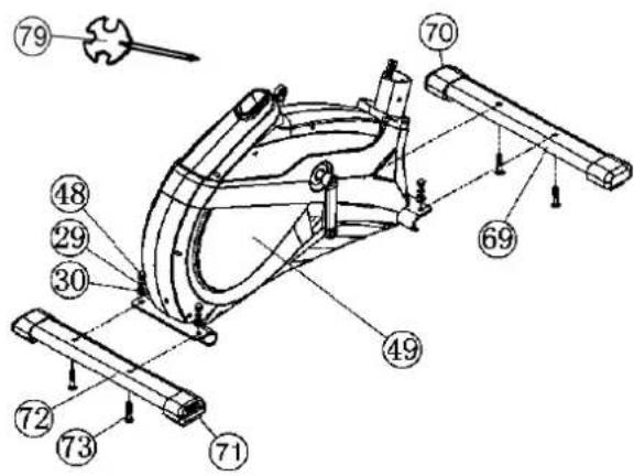
STEP1:
Attach the stabilizer (69 + 72)
- Attach the front stabilizer (69) assembled with front caps with transportation roller (70) to main frame (49) by using bolts M8x45 (73), washers (30), spring washers (29) and cap nuts (48).
- Attach the rear stabilizer (72) assembled with height adjustable caps (71) to main frame (49) by using bolts (73), washers (30), spring washers (29) and cap nuts (48). (For uneven floor, you can adjust the height at rear caps (71) and secure for stable position)
STEP 2:
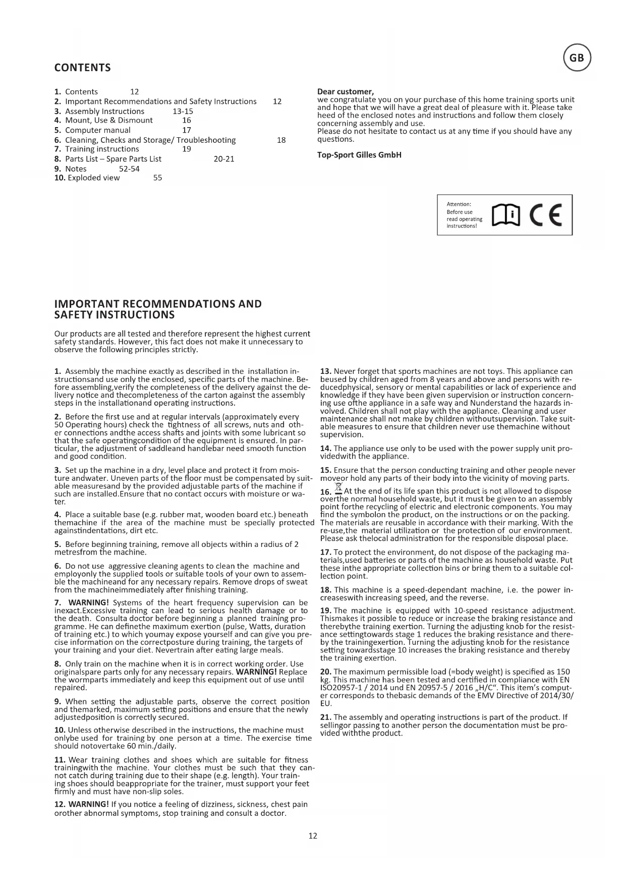
Attach the pedals (59L+59R).
- Attach the pedal straps to the pedals (59L+59R). (The pedal strap and pedals are marked with "L" for left and "R" for right.)
- The pedals (59L+59R) are marked with R for right and L for left. Right and Left are specified as viewed seated on the machine during training. Connect each pedal (59L+59R) to the matching pedal crank (60L+60R). (NOTE: The right pedal R should be threaded on clockwise. The leftpedal L should be threaded on counter-clockwise.)
STEP 3:
Attach the handlebar support (21) at main frame (49).
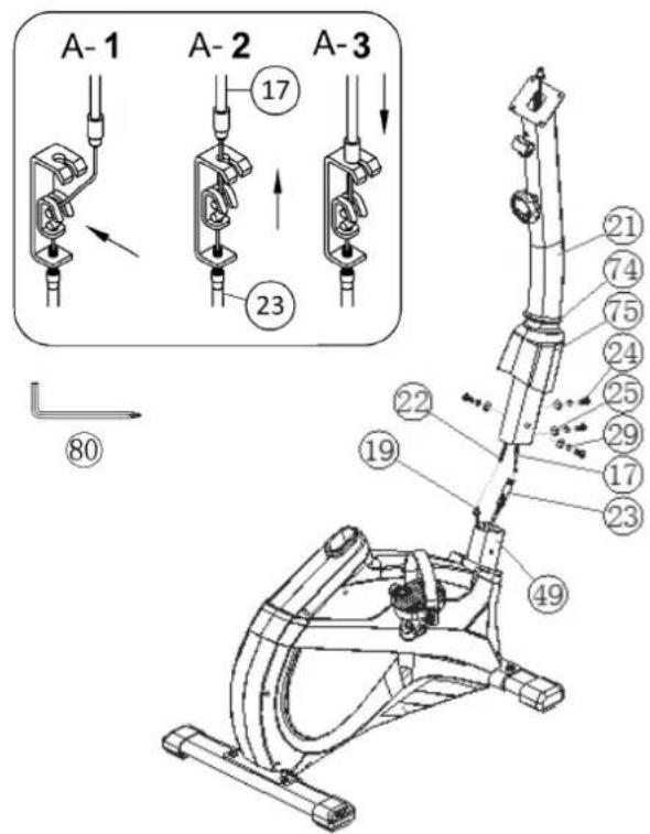
- Push the rubber ring (74) and the support cover (75) onto handlebarsupport (21).
- Hold the handlebar support (21) with the computer cable (22) against themain frame holder. Connect the plug for the computer cable (22) coming out of the bottom of the handlebar support (21) of the computer with the matching plug for the sensor cable (19) coming out of the main frame (49). (Note: The computer cable harness (22) projecting from the support (21) must not slide into the tube, as it is required for later steps of installation.)
- Connect the resistance control (17) to the bracket of lower section cable tension (23) (See figure [1]-[3]). Before this step of the installation, it is advisable to adjust the resistance setting to the highest stage, at which the cable extends furthest from the sheath. Put the lowest part of cable (17) into the small hook (figure 1). Pull it (figure 2) until the small hook get in higher position and then insert the cable (17) onto the bracket (23) (figure 3).
- Place the handlebar support (21) in the loca- tor provided for it in the main frame (49). Ensure that the cable connections made in step 3 are not squashed. When putting the steering tube in place, push the former slowly down into the locator in the main frame. Screw the handlebar support (21) onto the base frame (49) with the screws (24), spring washers (29) and washers (25).
- Push the handlebar support cover (75) with rubber ring (74) into right position to cover up the screw connection point.

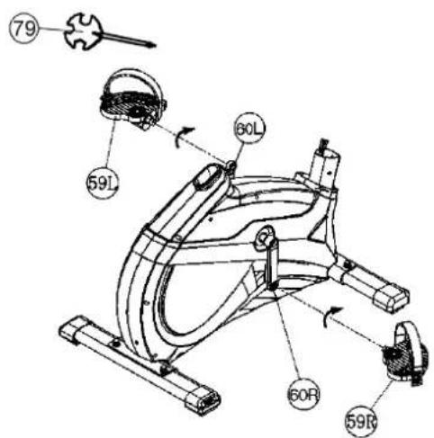

STEP 4: Installation of saddle (9) and saddle support (16).
- Push the saddle (9) with saddle bracket into the movable saddle slide (10) and tight it up into desired incline position.
- Place the seat slide (10) into the holder of saddle support (16), set it at the desired horizontally position and tighten it by using washer 10/25 (64) and hand grip nut (65) at triangular block (11).
- Insert the saddle support (16) into the provided holder of the main frame (49) and secure at the desired position by screwing in the quick release (18). (Note: To screw in the quick release (18), the threaded hole in the mainframe (49) and one of the holes in the saddle support (16) must be aligned. Furthermore, ensure that the saddle support (16) is not pulled out of the main frame beyond the marked maximum position. The setting of the saddle post can be adjusted as desired later. For this, the quick-release (18) must be loosened by only a few revolutions, the cap of the lock must be pulled away and the saddle adjusted. Then secure the new setting by tightening the quick release (18).
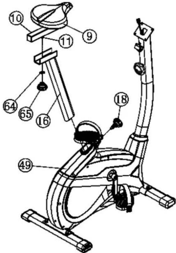
STEP 5: Attach the handlebar (6) at handlebar support (21).
-
Guide the handlebar (6) through the holder at handlebar post (21), put the pulse cable (5) through the hole and close the bracket of handlebar holder.
-
Attach the front handlebar cover (13) at handlebar and screw the handlebar (6) in desired position at the handlebar post (21) and tighten firmly with distance tube (14) and handlebar screw (15).
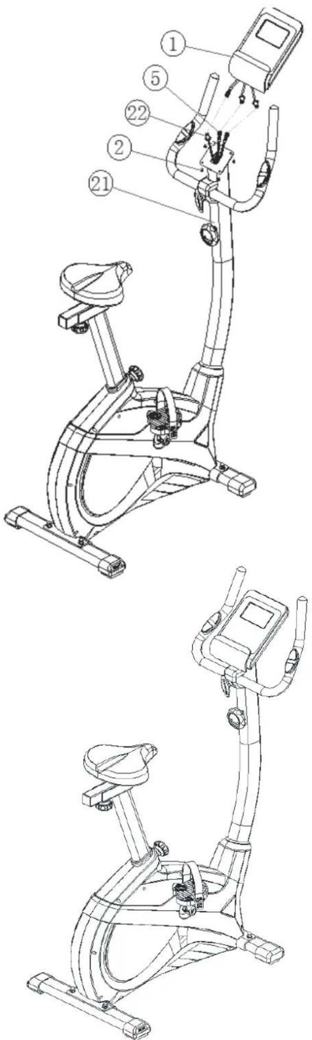
STEP 6: Attach the computer (1) at handlebar support (21).
- Push the plug of the connecting cable (22) and pulse cable (5) into the associated socket of the computer (1).
- Place the computer (1) on top of handlebar support (21) and attach it with the screws (2). The screws for assembly you find on backside of computer.
STEP7:
Checks
- Check the correct installation and function of all screwed and plug connections. Installation is thereby complete.
- When everything is in order, familiarise yourself with the machine at alow resistance setting and make your individual adjustments.
Note:
Please keep the tool set and the instructions in a safe place as these may be required for repairs or spare parts orders becoming necessary later.
Transportation of Equipment:
There are two rollers equipped on the front foot. For moving, you can lift up the rear foot and drive it to where you would like to locate or store it.
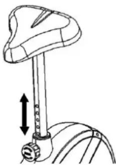
Adjustment - Seat Position
For an effective workout, the seat must be adjusted properly. While your are pedaling, your Knees should be slightly bent when the pedals are in the farthest position. In order to adjust the seat, unscrew the knob few turns and draw it out slightly. Adjust the seat to the right height, then release the knob and tighten it all the way.
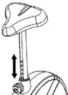
Important:
Make sure to put the knob back into place in the seat post and tighten it completely. Never exceed the maximum height of the seat. Always get off the bicycle before making any adjustment.
A biomechanically optimal seating position ensures optimum power transmission. The aim is that the existing force as large as possible arrives on the pedals and the muscles with optimal effect works. The seat position affects which muscles are in use primarily in essence. The right handlebar position is responsible for keeping the upper body portion. Is the handlebar settings chosen horizontally so you get an athletic posture. With each further step towards the body, you adjust a more relaxed attitude. To adjust the handlebar, simply loosen the screw handlebar until the handlebar can brought into the desired position and tighten them after adjustment again firmly.
To avoid any problems such as back- / knee pain or numbness in the feet through bad seat position on the bike, the maintenance of a proper adjustment of the saddle and handlebar we strongly recommend.
Mount, Use & Dismount
Mount:
a. After the seat is adjusted to properly position, lead one feet across the bottom unit and hold yourself at handlebar tightly.
b. Place one pedal in lowest position and slide your foot onto the pedal below the pedal strap to get a stabile foot position.
c. Now you can take a seat, slide the other foot into the second pedal and start your training.
Use:
a. Keep you hands on the handlebar, and both feet are insert into retaining straps of both pedal properly.
b.Pedal your exercise bike by your both feet alternately.
c. Then you can increase the pedaling speed gradually and adjust braking resistance levels to increase the exercise intention.
Dismount:
a.Slow down the pedaling speed until it comes to rest.
b. Keep the left hand grabbing the left handlebar tightly, put your feet across over the equipment and land on the floor, then land the other one.
Note:
This training equipment is a stationary exercise machine used to simulate without causing excessive pressure to the joints, hence decreasing the risk of impact injuries.
Exercise bike offer a non-impact cardiovascular workout that can vary from light to high intensity based on the resistance preference set by the user. It will strengthen your muscles of legs and increase cardio capacity and maintain fitness of your body also.
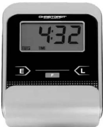
The supplied computer allows the most convenient training. Every value relevant to training is displayed in a corresponding window. From the beginning of the training session, the required time, the current speed, the approximate calorie consumption, the travelled distance and the current pulse rate are displayed. All values are counted from zero upwards. If you wish to see one value displayed constantly during training, select this with the "F" key. If you wish to see these values in constant alternation, select the "SCAN" function. The display then changes from one function to the next at intervals of approx. 6 seconds.
The computer is switched on by briefly pressing the F- key or simply by beginning training. The computer begins to register and display all values. To stop the computer, just stop training. The computer stops all measurements and retains the last attained values. The last attained values in the functions TIME, CALORIES and KM are stored and training can continue with these values when training is resumed. The computer switches of automatically approx. 4 minutes after training is stopped. All values attained until that time are stored and are displayed again when training is resumed. It is then possible to continue training from these values or to reset all functions to zero using the L- key.
DISPLAYS:
1. SPEED'' (KM/H) display:
The current speed is displayed in kilometres per hour. It is not possible to specify a particular value using the E^ key. The values last attained by this function are not stored. (Limit of the display: 999.9 km/h.)
The currently required time is displayed in minutes and seconds. It is possible to specify a particular value using the „E“ key. If a particular time has been specified, the remaining time is displayed. When the specified value is attained, this is indicated by an acoustic signal. The values last attained by this function are stored. (Limit of the display: 99 minutes.)
3. DIST (KM) display:
The current status of the travelled distance is displayed. It is possible to specify a particular value using the ^ key. If a particular distance has been specified, the remaining distance is displayed. When the specified value is attained, this is indicated by an acoustic signal. The values last attained by this function are stored. (Limit of the display: 999,9 km.)
4. CALORY (CAL) display:
The current status of the consumed calories is displayed. It is possible to specify a particular value using the E key. If a particular consumption has been specified, the remaining number of calories to be consumed is displayed. When the specified value is attained, this is indicated by anacoustic signal. The values last attained by this function are stored. (Limitof the display: 999,0 calories.)
5.,PULSE" display:
The current pulse rate is displayed in beats per minute. It is possible to specify a particular value using the E key.
The values last attained by this function are not stored. (Limit of both displays:40 - 240 pulse beats per minute.)
Note:
For pulse measurement, the two contact surfaces of the pulse measuring handle unit must be gripped simultaneously. The contact surfaces should be located centrally in the palms of the hands.
6..SCAN" function:
If this function is selected, the current values of all functions are displayed successively in a constant sequence approx. every 5 seconds.
7. STOP display:
Display of Stopmode. Presets can be set.
KEYS:
1.,F" key (Fuction):
Pressing this key once briefly makes it possible to change from one function to another, i.e. the respective functions can be selected for which entries can be made using the "E" key. The currently selected function is indicated in the window.
2, ^ key (Enter):
By pressing this key once, it is possible to specify values step by step in the respective functions. For this, the desired function must firstly be selected using the F^ key. Holding the key pressed activates faster running. When training begins, the specified values are then counted down to zero.
3. L^ -key = (Delete):
When this key is pressed briefly, the values chosen with the nFn^ key are reset to zero. If the key is held longer (approx. 3 seconds), all last attained values are deleted.
Replacing the batteries:
-
Open the battery compartment cover and then remove the used Batteries.(If the batteries should leak remove them under increased considering that the battery acid is not into contact with skin come and clean the battery compartment thoroughly.)
-
Insert the new batteries (type (AAA) 1.5V in the correct order and taking into account the polarity in the battery compartment and close the batterycover so that it clicks into place.
-
If the computer does not pick up immediately, the function should batteries are removed for 10 seconds and re-inserted.
-
The empty batteries properly in accordance with the disposal regulations disposed of and do not give residual waste.
Battery compartment
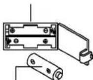
AAA batteries
1.Cleaning
Use only a less wet cloth for cleaning. Caution: Never use benzene, thinner or other aggressive cleaning agents for surface cleaning as this damage caused. The device is only for private home use and for use suitable indoors. Keep the unit clean and moisture from the device.
2.Storage
Remove the batteries from the computer while intending the unitfor more than 4 weeks not to use. Push the saddle slide toward the handlebar and the seat support tube as deeply as possible into the frame. Choose a dry storage in-house and put some spray oil to thepedal bearings left and right, to the thread of the handlebar bolt, and on the thread of the quick release for saddle support. Cover the bike to protect it from being discolor by any sunlight and dirty through dust.
3.Checked
We recommend every 50 hours to review the screw connections fortightness, which were prepared in the assembly. Every 100 operating hours, you should put some spray oil at the pedal bearings left and right, to the thread of the handlebar bolt and to the thread of quickrelease for saddle support.
TROUBLESHOOTING
If you cannot solve the problem with the following information, please contact the authorized service center.
| Problem Possible Cause Solution | ||
| Computer has no value at Dis-play if you press any key. | No power adapter is well plugged or wall power is without power. | Check that the power adapter is properly plugged in, possibly with another electric device check if the wall power is fine. |
| Computer is not counting data and do not switch on after start cycling. | Sensor impulse missing base on not well plugged connection. | Check the plug connections at computer and inside of handle-bar support. |
| Computer is not counting data and do not switch on after start cycling. | Sensor impulse missing base on not cor-rect position of sensor. | Take off the cover and check the distance between magnet and Sensor. The magnet at turning belt wheel should have only less than < 5mm distance against the sensor position. |
| No pulse value. | Pulse cable is not plugged in. | Check the separately pulse cable is well connected with computer. |
| No pulse value. | Pulse sensors not well connected. | Screw out the screw for pulse measurement and check if plugs are well connected and no damage at pulse cable. |
| Resistance don’t change. | Connection of resistance not well. | Check the resistance connection inside of handlebar support as manual mention. |
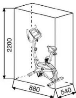
Training area in mm (for home trainer and user)
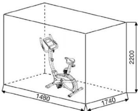
Free area in mm (Training area and security area (rotating 60cm))
You must consider the following factors in determining the amount of training effort required in order to attain tangible physical and health benefits:
1. Intensity:
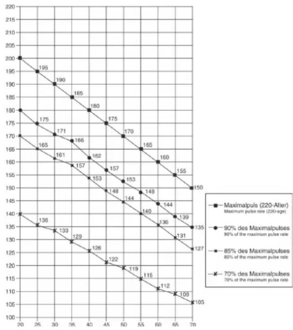
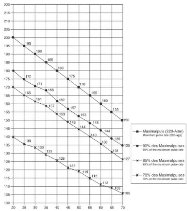
The level of physical exertion in training must exceed the level of normal exertion without reaching the point of breathlessness and/or exhaustion. A suitable guideline for effective training can be taken from the pulse rate. During training this should rise to the region of between 70% to 85% of the maximum pulse rate (see the table and formular for determination and calculation of this).
During the first weeks, the pulse rate should remain at the lower end of this region, at around 70% of the maximum pulse rate. In the course of the following weeks and months, the pulse rate should be slowly raised to the upper limit of 85% of the maximum pulse rate. The better the physical condition of the person doing the exercise, the more the level of training should be creased to remain in the region of between 70% to 85% of the maximumpulse rate. This should be done by lengthening the time for the training and/or encreasing the level of difficulty. If the pulse rate is not shown on the computer display or if for safety reasons you wish to check your pulse rate, which could have been displayed wrongly due to error in use, etc., you can do the following:
a. Pulse rate measurement in the conventional way (feeling the pulse at the wrist, for example, and counting the number of beats in one minute).
b. Pulse rate measurement with a suitable specialised device (available from dealers specialising in health-related equipment).
2. Frequency
Most experts recommend a combination of health-conscious nutrition, which must be determined on the basis of your training goal, and physical training three times a week. A normal adult must train twice a week to maintain his current level of condition. At least three training sessions a week are required to improve one's condition and reduce one's weight. Of course the ideal frequency of training is five sessions a week.
3. Planning the training
Each training session should consist of three phases: the warm-up phase, the training phase, and the cool-down phase. The body temperature and oxygen intake should be raised slowly in the warm-up phase. This can be done with gymnastic exercises lasting five to ten minutes. Then the actual training (training phase) should begin. The training exertion should be relatively low for the first few minutes and then raised over a period of 15 to 30 minutes such that the pulse rate reaches the region of between 70% to 85% of the maximum pulse rate. In order to support the circulation after the training phase and to preventing or strained muscles later, it is necessary to follow the training phase with a cool-down phase. This should be consist of stretching exercises and/or light gymnastic exercises for a period of five to ten minutes.
4. Motivation
The key to a successful program is regular training. You should set a fixed time and place for each day of training and prepare yourself mentally for the training. Only train when you are in the mood for it and always have your goal in view. With continuous training you will be able to see how you are progressing day by day and are approaching your personal training goal bit by bit.
Calculation formula:
Maximum pulse rate = 220 - age (220 minus your age)
90% of the maximum pulse rate = (220 - age) x 0.9
85% of the maximum pulse rate = (220 - age) x 0.85
70% of the maximum pulse rate = (220 - age) x 0.7
WARM UP EXERCISES (WARM UP)
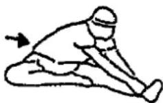
Start your warm up by walking on the spot for at least 3 minutes and then perform the following gymnastic exercises to the body for the training phase to prepare accordingly. The exercises do not overdo it and only as far run until a slight drag felt. This position will hold a while.


Reach with your left hand behind your head to the right shoulder and pull with the right hand slightly to the left elbow. After 20sec. switch arm.
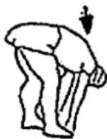
Bend forward as far forward as possible and let your legs almost stretched. Show it with your fingers in the direction of toe. 2 x 20sec.
Sit down with one leg stretched out on the floor and bend forward and try to reach the foot with your hands. 2 × 20 sec.
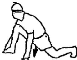
Kneel in a wide lunge forward and support yourself with your hands on the floor. Press the pelvis down. Change after 20 sec leg.
After the warm-up exercises by some arms and legs shake loose.
Don't finish the exercise phase abruptly, but will cycle leisurely something without resistance from to return to the normal pulse-zone. (Cool down) We recommend the warm-up exercises at the end of the training be conducted and to end your workout with shaking of the extremities.
PARTS LIST - SPARE PARTS LIST
Art-Nr:
2006
Technical data: Issue
28.07.2020
Magnetic brake system
- Aprox. 8kg flywheel mass
10-gears manual resistance
- Hand pulse measurement
- horizontally and vertically adjustable saddle (quick release)
- Saddle and handlebar inclination adjustable
Floor level compensation
- Computer showing: speed, time, distance, approx calories and pulse frequency, Holder for smartphone / tablet
- Input of limits for time, distance and approx calories
- Announcement of higher limits
- Load max. 150 kg (Body weight)
This product is created only for private Home sports activity and not allowed to us in a commercial or professional area. Home Sport use class H/C
Please contact us if any components are defective or missing, or if you need any spare parts or replacements in future:
Internet service- and spare parts data base: www.christopeit-service.de
Space requirement approx. [cm]:
L 88 x W 54 x H 136
Items weight [kg]:
28
Exercise space approx. [^2 ]
2,5
0.510.1520.3530.4050.6070.8090.100
051015202530405060708090100
| Illustration No. | Designation Dimension mm Quantity Attached to Illustration No. | ET-Number | ||
| 1 | Computer | 1 | 21 36-2006-03-BT | |
| 2 | Screw | M5x10 | 4 | 1+21 39-9903 |
| 3 | Foam | 2 | 6 36-1410-04-BT | |
| 4 | End cap | 2 | 6 39-9847 | |
| 5 | Pulse cable | 2 | 1+8 36-1122-09-BT | |
| 6 | Handlebar | 1 | 21 33-1410-04-SI | |
| 7 | Self-tapping screw | M4x15 | 2 | 6+8 39-9909-SW |
| 8 | Hand pulse sensor | 2 | 21 36-9806206-BT | |
| 9 | Saddle | 1 | 10 36-9806210-BT | |
| 10 | Seat slide | 1 | 9+16 33-1106107-SW | |
| 11 | Triangular block | 1 | 10+16 33-9211-08-SI | |
| 12 | Square tube plug | 2 | 10 36-9211-23-BT | |
| 13 | Plastic cover | 1 | 6 36-9103-07-BT | |
| 14 | Tube spacer | 8x24 | 1 | 15 36-9806228-BT |
| 15 | Handlebar screw | 1 | 21 36-9211-16-BT | |
| 16 | Seat post | 1 | 10+20 33-1907-05-SW | |
| 17 | Tension control | 1 | 23 36-2006-04-BT | |
| 18 | Quick release | M16 | 1 | 49 36-1907-06-BT |
| 19 | Sensor | 1 | 23+49 36-2006-07-BT | |
| 20 | Plastic insert | 1 | 49 36-1907-08-BT | |
| 21 | Handlebar post | 1 | 49 33-2006-02-SW | |
| 22 | Connection cable | 1 | 1+23 36-2006-05-BT | |
| 23 | Tension cable | 1 | 17+51 36-2006-06-BT | |
| 24 | Allen bolt | M8x20 | 4 | 21+49 39-9886-CR |
| 25 | Curved washer | 8//19 | 4 | 24 36-9966-CR |
| 26 | C-clip | C17 | 1 | 34 36-9825320-BT |
| 27 | Washer | 17//22 | 1 | 34 39-10135 |
| 28 | Bearing | 6003-2RS | 3 | 49 36-9806214-BT |
| 29 | Spring washer | for M8 | 8 | 24+73 39-9864-VC |
| 30 | Washer | 8//16 | 4 | 73 39-9962 |
| 31 | Washer | 6//14 | 4 | 36+43 39-9863 |
| Illustration No. | Designation Dimension mm Quantity Attached to Illustration No. ET-Number | |||||
| 32 Wave washer | 17.5//22 1 34 36-9918-22-BT | |||||
| 33 Nylon nut M6 | 1 36 39-9816-VC | |||||
| 34 Pedal axle | 1 49 33-1907-07-SW | |||||
| 35 | Belt | 390J6 | 1 | 34+55 | 36-9913116-BT | |
| 36 Double-thread screw | 1 51 36-161 | 1-22-BT | ||||
| 37 Spring | 1 51 36-980 | 6217-BT | ||||
| 38 Nut | M6 2 36 39-9861-VZ | |||||
| 39 Idler wheel | 1 45 36-980 | 5216-BT | ||||
| 40 | Screw | M5x40 | 1 | 17+21 | 36-10111-VC | |
| 41 | Allen bolt | M8x20 | 2 | 39+45 | 39-10095-SW | |
| 42 | Nut | M8 | 1 | 41 | 39-10031 | |
| 43 Allen bolt | M6x15 | 3 19+52 | 39-9911 | |||
| 44 | Washer | 17//22 | 1 | 34 | 39-10135 | |
| 45 Idler wheel bracket | 1 49 33-1907-06-SW | |||||
| 46 Spring | 1 45+49 | 36-9806217BT | ||||
| 47 Curved washer | 5//14 | 1 40 36-10406 | ||||
| 48 Cap nut | M8 4 73 39-900-SW | |||||
| 49 Main frame | 1 21 33-2006-01-SW | |||||
| 50 Magnet | 1 34 36-9825506-BT | |||||
| 51 Magnet bracket | 1 52 33-161 | 1-14-SI | ||||
| 52 | Axle of magnet bracket | 1 | 51 | 36-9225-11-BT | ||
| 53 C-clip | C11 | 1 52 36-9514-26-BT | ||||
| 54 | Wave washer | 12//17 | 1 | 52 | 36-9824-21-BT | |
| 55 Flywheel | 1 49 33-150 | 7210-SI | ||||
| 56 Belt wheel | 1 34 36-1105-13-BT | |||||
| 57 Axle nut | M10x1.25 | 2 55 39-9820 | ||||
| 58 Axis protection piece | 2 56 36-112 | 3-28-BT | ||||
| 59L | Pedal left | 1 60 36-9806229-BT | ||||
| 59R | Pedal right | 1 | 56 | 36-9806230-BT | ||
| 60L | Crank left | 1 | 34+59L | 33-1105-08-SW | ||
| 60R | Crank right | 1 | 34+59R | 33-1105-09-SW | ||
| 61 Crank cover | 2 62 36-1907-07-BT | |||||
| 62L | Chain cover left | 1 | 49+62R | 36-2006-01-BT | ||
| 62R | Chain cover right | 1 | 49+62L | 36-2006-02-BT | ||
| 63 | Connection shaft | 3 | 62L+62R | 36-1508-10-BT | ||
| 64 | Washer | 10//25 | 1 | 11 | 39-9989-SW | |
| 65 Hand grip nut | M10 | 1 11 36-1907-09-BT | ||||
| 66 | Self-tapping screw | M4.5x25 | 6 | 62R | 39-9825338-BT | |
| 67 Drill screw | M5x15 | 5 62 39-10190 | ||||
| 68 | Drill screw | M5x20 | 10 | 17+62 | 39-9903-SW | |
| 69 Front stabilizer | 1 49 33-1907-03-SW | |||||
| 70L | Front stabilizer cap left | 1 | 69 | 36-1907-10-BT | ||
| 70R | Front stabilizer cap right | 1 | 69 | 36-1907-11-BT | ||
| 71 Rear stabilizer cap | 2 72 36-1907-12-BT | |||||
| 72 Rear stabilizer | 1 49 33-1907-04-SW | |||||
| 73 | Carriage bolt | M8x45 | 4 | 49,69+72 | 39-9953 | |
| 74 Rubber ring | 1 75 36-1907-05-BT | |||||
| 75 Handlebar cover | 1 21 36-1907-04-BT | |||||
| 76 | Axle bolt | M8x20 | 2 | 56+60 | 39-9886-CR | |
| 77 Crank plug | 36-9840-15-BT | |||||
| 78 Allen bolt | M8x20 | 1 45 36-10095-CR | ||||
| 79 Combination wrench | 1 | 36-9107-27-BT | ||||
| 80 Allen key wrench | 1 | 36-9107-28-BT | ||||
| 81 Screw | 3x10 | 2 19 39-10127-SW | ||||
| 82 | Assembly and exercise instruction | 1 | 36-2006-08-BT | |||
Chere cliente, cher client,
3. Planning van de training
PepedncnoIb3ObaHHnEM
PpOHTaTe HcTpyKuHIO
no ekcnnyataaun!


BAKHBIE PEKOMEHDAUIN N YKA3AHN NO 6E3ONACHOCTN
Haun 3denn npnHnnnaIbHo NODBepraTc nCbTaHnM CO CTOpBoH i TEM cBbIM OTBeuAOT AKTyIbHOMy, CaOMY BblcOKOMy CTaHApTy 6e3onachOCTn. Ondako 3OT fakr He ocbo6kdaet ot 063aHHocn CTporo co6bIpaTb npnbedeHHbe Hxke npnHnnnaIbHie Yka3aHnR.
- MoHTnPOBaTb TpeHaepe B ToCHOM COOTBeTCTBNN C MOHTaXHOHNCTpyKUne N IcNOJb3OBA Tb ToIbKO Te OTHOCaUneC K TpeHaepeyDeTaN, KOtOpbe pnpIoNoXeHbI dN Ma MOHTaXa TpeHaepeA. PepeI npoBeHeMe MOHTaXa NpOBePbN KOMnJIeKTHocTb NocTabKN Ha OCHOBAHnHaKaJaDHOH N KOMnJIeKTHocTb CoepKIMOrO KapTOHHO KoPo6Kn-YNaKOBKnIO MOHTaKy N EKcnPlyaTaun.
- Npeepnepbbim nCnoB3oBaHne m upeep3 peryIrpHbIe HHTepBaIbIBpeMeHn IPOBepaTb IPOUHOCTb NocAdKn BcEx BINTOB, raeK I npOuHX CoeDHNHeH n TcEm, TTObI oEceNeHTb HaJeKHOe 3KcnNyaTaunOH-Hoe COctOAHHe TpeHaXepa.
- Pa3MeCTNb TpeHaKepe C cyom, POBHom MecTe N ppeOxApaHNTb ETO OTEBArN CblpoCTN.CKOMNEHCIOPOBaT HEPOBHOCT NoIa ChET COOTBeTCTByIOxN MEOP, OCyUeCTBnaEMybHex HA NOy, N ppeDyCMOTpeHn BHXdJI 3T0R, KOTCHpyEmbX DeTaeN TpeHaxepa, eCNI OHN ECTb Ha DAHHOMTpeHaKepe. VckLIOuHTb KOHTAKT C bIarO N cbIpocTbIO.
- Ecni cneJyET 3aunTb MeTo p3MeueHn TpeHaKeep B Oco6eHocHTNOT npoabINBAHnA, 3arpa3HeHn n TOMY noo6Horo, noIOKhtb noDTpeHaepe NOxOJaIyIO, HeckOnb3JyIO npoknAky (HaipnMep, pe3HOBbIKOBpNK, DEpeBHNyIO nTIy nI. n.).
- Ппелтpeнровковуддь ВспpeДметыВ радиуce 2 МетровВokргтpeнхера.
6.ДЯоиткп.TpeHaxepa HeIb3Я NOIb3OBaTbCа arpeccBbIMNoHCHTHIMCpeCTBaMn,aДЯMOHTaHaN BO3MOKHoro peMOHTANCIOJIbOBArTOJkoNOCTaBHeHHB BMeCTe C Hm NIN NOxOJaUncO6CTBeHHB NHeCTpyMeH.TyaIaNt c TpeHaxepa Cnebl NaToTa cpa3y Je Nocle OKOHuaHn TpeHnpOBKn. - BHUMAHNE: CnCTembl cepdeuHou qactoTb KOHTpObl MOYr 6blTb HETOCHbI. NObUbiEHHHa TpeHNPOBa MOKET K cepbE3HOM YmRHeHuecKOMyOBpeDeHIO HIN BeDyt K cmeptN. HeKaBIMnOpOBaHHa N Upe3MePbAHTpeHNPOBa MOKET npuHmHTb BpeD 3IOpOBbI. ITo3OTMY nepeD TEM, KAK pNCTynatb K ueJeHApBHeHOnTpeHNPOBKe, POKOHcyJbTHpOBAcbc C COOTBcTByUOUM BpaOM. OHMOKET ONpeJIb, KAKIM MAKCMNAHbHM HarpykAM (Nybc, BaTT, npdoJIKNTeBHOCTb TpeHNPOBKn I. D.) pa3peSaaTcnoDBepraTbCn, NaTbTOHyIO IHOPMaMQIO O npabInbHOM NoIooHEHH TeNa BOBpema TpeHNPOBKn, O ceJAX TpeHNPOBKn I O nITAHNN. 3anpeuaetcTpeHNPOBaTcBnocLe ObNbHOH ebl.
- TpeHpoBaTbca Ha TpeHaKepe ToIbko TOrda, KOrDa OH pa6oTaet-6e3ynpeHNO.ДЯ Bo3MOKHOrpeMOHTa NcNoB3OBaTb ToIbko OpRnHaBHe3anaChbue qACTN. BHIMAHNE: Ecln Yactn npn NcNoB3oBAHN yCTpoiCTBaTbAHOrTa Ype3MepHo rOpau OH 3aMeHAnOT ee 6bln CPOHbN OH eUeHe rapaHTnpYOT yCTpoCTBO pOtnIB NcNoB3OBAHn DO Tex NOp NOKa 3TOB CoCTOAHN 6bln NOMeUeHbI.
- HactpanBaB perynnpyembIe deTaN, cIeIITb 3a npabINbHbIMNoLOKHeHnEMnIOOTB., yUHTbBAbT NOMEeHHYo MAKcMaJIbHHyIO NO3uHIOHACTPOKnIOEHNBOHACrpoEHNOHOLOKeHn.
-
EcnB pykoBOcTB He yka3HO mHOrTo TpeHaKePOM MOKeTIOJIbOBAtCBaTobKo OINH CELOBeK. Bpemr TpeHnPOBKn HE DOJIKNHO 6blONPeBOxCOnITb B CELOm 60 Min./exeDHeHo.
11.Heo6xoJIMHOocntb TpeHnpOBOHyIOeKdyN O6yBb, KOtOpbl- enoXoJATnO3dopOBNTelbHO TpeHnpOBKn Ha TpeHaepe. OdeKa DOnkHaTakO, QTo6bNo CboE φOpMe (HanpMep, DInHe) OHa He MorIa3aueNtCB So Bpmr TpeHnpOBKn.CneDyET No6bpatb TpeHnpOBOHyIOo6yBb, KOTOPA NOxOoNT K TpeHaepey, ObcneHnaeYCTOuHBOCTb dIra Hor N IMeet HecKoIb3aIyIO nooWBy. -
BHIMAHNE: Ecnn Bo3HnKHyr rOIOBokpyKeHne, ToOHota, 60JI8 rpydI npDyAHOHaJIbHe CmNITOMbl, npePbT bTeHNPOBky N O6pATNbCk CCOOTBETCTBYUcMBy BPAUY.
13.CneNyET npnHcHmnaJIbHO yueCTb, 7OTo cnpTbHBhe cnapdbl-HeIrpWsk. 3TO YcTPOJCTBO MOKET 6bITcNcNOb3oBAHO DeTeB B O3PacTe O8JIe Nlnc COrpaHnHBeHHIMn FIm3HNeCKHMn, CeHCOPHbIMn IINYMCTBEHNbHMnCNOcO6HOCTMn INN HexBaTKOn ONbTa n 3HAHN, ECNN OHNPINOHBnAD3Op INN NOpO6HbE NHCtpyKUnn NO 6e30NaChOMy NCIOb3OBaHNOpnIPbopa, a TAKKe, BO3MOxHO, BO3NTAHm ONaCHOCTe, CBsAHHBX CNOHmAnabc, DeTI He MORYr IrgPATb C doma CNoptBNHO O6OpyDoBaHN.OuNCtKa nTexHnueckoe o6cLyKnBaHne HE DOJXHO BInONHbTcBJeTee63 pncMOTpa. NCKIOUHTb BO3MOXHOcNIOb3OBaHN TpeHaHexepaDeTbMn 6e3 HAd3opa, pnpHAB COOTBETCTByIOue MePbI. - 3TO yCTPOINCTBO MOKET pa6oTaTb TOJbKO C BKNIOUeHHbIM 6IOKOMNITAHIA.
15.CneIbTaTeM,HTo6bTpeHnpyIOueeNnpyrNe Iuca HNKOrda HeNoNaJaIa KaKIMNu-ILoo CaaTmH CBOero TEa B 3OHy eEe DBeHXyU XHCxRdTeAteJn IYTo6b OHN He HaxoDMINCb TaM. - B KOHcE cPOKa CLYK6bI 3OTn PpOyKr He DOnJKeH 6bITb yTNiN3NPOBAHB DOmaunHe OTXoDBa, a DOnJKe H6bITb OTdHa HCOpHbI NynHKr YTNlN3AuauNcNOJb3OBOAHBHX 3JeKTPueeCKIN N3JeKTPoHHbIX npN6OBop. Ha 3ToyKa3bIBaet CmMBo HA npOyKe, Ha nHCTpyKuNN no 3KcnNyataaUNuMHa yNakOBke.Bce MATEPAHbI MOrY 6bITb CHOBa NCNoJb3OBAHbI corNaCHO MapKnPOBKe.Pnnp NOBTOPHOM NcNoJb3OBAHN, BTOPNUHNepepa6OTKe NNDPyrhXfOpMax BTOPNUHORO NCNoJb3OBAHN cTApbIX npN6OBop Bb BVHocnte CBOBkLaD B 3aUnTy OkpyKaIOUe cpeDb. PnKaJIyCtA, y3HaIte B KOMMyNAhBOM ynpabLeHHn aDpec 6bn3JekaUeroC6OpHOrO NYKTA yTNlN3aUN.
17.YuHTbIBa Tpe6oBaHnHa 3KoIorHn, He ydaIaTb ynaKOBouHbM MaTePnJi, INpACXoOBAHbHbE 6bataeKn n DetaiN TpeHaxepa BMeCTc 6bITOBIMNtOxAOMn, a KlaTb Nx B IpeyCMOTpeHHbIe IraIeTORO KOHTeHepBc-6OpHNKn nn CdaBaTb Nx COOTBeTCTByIOUme NyHKtbl c60pa YTNlbCbIPbR.
18.3TOT TpeHaKepe npedctabIeTe coboi cnopTNBbI chapd,deHCTByoouh 3BaMCUMOCTN O CKOcTH, t.e. ero MOUHOCTb BOpactaETNO Mepe yBEnueHnAqTObl BpaueHn HnAo6Opot.
19.DaHHbI npH6Op ABJAEcTc 3ABNCMbIM OT cKOpOCTn, T.e. C yBEnHeHnEMHnCnla OOBOPOTOB MOUHOCTb YBEHNHBAeTCN HAObOPOT. Pnp-6Op CnAb6HeHnФHcNpYEmoB 8-Mn NOnIOxEHnX peryNPOBKO coPOTNBLeHn, KOTOPaRNOBOLReT CHN3NTb LNo6 NOBbICNTb TOPMO3HOe CONPOTNBLeHnE, TMcSAMbI, TpeHNPOBOHyHO HArpy3Ky. PInr 3TOM BpaSeHne pyKn peyNPOBKKCONpOTNBHeHn B HApPaBHeHn CTyeNHn I BeTe K ChNKeHnTOpMO3HOrOCONpOTNBLeHn, TM cAMbIM, TpeHNPOBOOH Harpy3Kn. BpaSeHneepKnpeyNPOBKN CONpOTNBLeHn B HAnpaBLeHn CTyeNHn 10 BeTe K NoBbIeHnTOpMO3HOrO CONPOTNBLeHnN, TM cAMbIM, TpeHNPOBOOHHaRPy3Kn.
20.Дуonymа Мakcmaьнаг Harpy3ka (= Bec TeNa) yctaHOBNeHa B150 Kr. KomlbopTe npwoJI nCbItaHnI cepTnФHnauNo cornacho Hopme EN ISO 20957-1 / 2014 und EN 20957-5 / 2016 „H/C" u EMC Directive 2014/30/EU.
21.Инстуким no c6bopke n 3KcNnyataunn doJHKbI paCCMaTpNBaTBcRakKaHCTb npOyKTa.3Ta DOkyMeHTaUNdJHKHa npEOCTaBnTbCernpnOdaKe Hn nepeDaue npOydTa.
IOnKaIyIcTa, BbHbTe Bce OTdJIbHbIe qactn n3 Kopo6Kn I npOBepBe IN HA KOMNJIeKTHOCTB COOTBeTcBm Co cneuΦkaueNe. PpIMNTe BO BHMaHe, YTO HEKOTOpbe qACTn ppeBaPteNbHO CMOHTnpoBaHb.I Bpema yCTaHOBKn 30-40MHN.
UAR1: MoHTaX nepeDHeN 3aDHeN HOKeK (69+72).
- YcTaHOBHTe nepeHIOHOHKy (69), cMOHTPOBAHHYIO C KOJIaayKaAMn TpaHCNOPTNPOBOHybIM 6IoKOM (70) Ha OCHOBHYo pamy (49) KpENKOPIHPkyTne e C NOMOsbIO KpeNekHBix BoTob M8x45 (73), npyKHHbIXsaM6 (29) NOkLaNDbIX saM6 (30) u KOJIaauKOBbIe raIKy (48).
2.YCTaHOBtE3ADHIO HOKky (72),CMOHnPOBaHHyC KOJINaUcAMn (71),HaOCHOBHyo pAmy (49) IN KpENKO pNkpyTnte ee c NOMIoBu NKpeKeNbIX60ToB (73),PNYKHNbIX WaN6 (29) NOKnAaHbIX Waa6 (30) IN KOJINauCKOBBe raiKn (48).(IN Ocne toro, KaB Bi CMOHnPOBaIIN Becb TpeHaJep, PpaBInHo BblCTaBNTe KOMNeHCaTopb (71) HepOBHcTn NoJa.3TNMB Bi npDynpTeHeHpeHamepeHhbe DnHexHnTpeHaJepa BO BpMa TpeHnPOKn.)
UAR2: MoNTaX neJaIe (59R+59L).
-
YcTaHOBnTe PmKcnpyuOune neHtbl neJaen Ha COOTBeTCTByUoUneNeDAn (59R+59L).
-
ctaHOBnTe nea (59R+59L) Ha pbYuarn neaJe (60L+60R). PdAunmeoT MapKnpoBky, R" npabOu n L' dJe BoBn. (BHMaHne: JeBa n npaba CTOPOHa NOpa3yMeBaIOr cnpHaXoJcEHn Ha TpehKepe B MOMeT TpeHpKnBn. Ppaba neaIb (59R)dONKHa Bpaatbcn No YacBOB CTpeKne, a neBa neaIb (59L) npoTHb YacBOB CTpeKN.)
UJAF 3: MoTAn onOpHoi Tpy6bl pyIa (21) Ha ochOBHyIO pamy (49).
1.BCTabTe MaHKeTy 06WNBa ONOpHO Tpy6b (75) n pe3nHOBoe KOJIbUO (74) Ha onOpHyTO Tpy6y ceLa (21).
2.Bo3bMnTe onOpHyTo ty6y pyra (21) c npedBaPntEhBO CMoHTnpOBaHHbIMCOeHNHtBbHM Ka6benem (22). CoeHNHte WTekep KOMnbTOpePHORoka6ena (22), BxIOaJnHI n3 onOpHO Tpy6b pyra (21), CO wTekepOMcePBODBnATeRAI (19), BxIOaJUero n3 OCHOBHO pAMbI (49).(BHMaHne! BxIOaJnHI n3 onOpHO Tpy6b (21) KOHeC KOMNbTOpePHORoka6ena (22) He doJIKeH 3anaDaTb Tpy6y, T.K. OH Bam eJe noHaOboNCTcnpn NocJeYIOuEe MoNTaKe). TaKHe 6obpaNoTHBMnHe Ha To, Yo6bInpN coeHNHeHH Tpy6 KomNbTOpeHBe Ka6eHn He 6bln 3aKaTbI.
3. PpOBeIe KOHe perynIOBKn cOnpoTnBneHnna (17) K pKpIeNHO TPOCOB TReN (23) n CoedmHte Hx dpyr C dpYROM, Ka NpeCtABNeHOba PcSyHKac c ([1]-[3]). PerynIOBky cOnpoTbNEHn yCTaHOBHT TaKyTObI TReA C rONOBKO BbIXoHnla Ka MOKHO DaJIbIe M3 O6uWNk. (YPoBeHb 10). Pocne Yero 3aueHnte rONOBKY Ha KOHc TReN perynIOBKncoPOTNBEHnHa KpOyOK, HaxoDauNcra Ha KpaC-HOM KpENLeHNn. (Pnc. 1). NotAHnte BCIO ONOPHyTOpybCy n PpUeNIIeHNOI rONOBKO TARNBepx Tak, 4TO6bl KpOuyKn B KpENLeHn NEpeMeCTnNlcb HApBepx (Pnc.2) n ObuWbKa KpENLeHn 3aCToNPOpNJAcB (Pnc. 3).
4.BCTabBe TOnOpHyTo py6y pyra (21) B COOTBETCTBYIOOe KpeNJIeHHeA OCHOBHO pame (49).O6paTInTe BHIMaHHe Ha To,TO6bI Ka6ebHoEOeDINHEHe Hte 3aIeMIAIOCb, N MeDJIeHHO BCTABBe TOnOpHyIOtp6y pyra (21) B COOTBETCTBYIOOe KpeNJIeHHe HA OCHOBHO pame. PpIKpyrTe TOnOpHyTOpyra (21) K OCHOBHO pame (49) c NOMOJbHO6IoTob (24), npyKHHbIX Wai6 (29) n NOkKnAdhix Waio6 (25).
5. BctaBbTe MaHKeTу O6uWbKa onOpHoi Tpy6bl (75)и pe3uHOBoe KoIbIo (74)Ha onOpHyIO Tpy6y ceNla (21).

UAR 4: MoHTaX ceIa (9) n cana3ok ceIa (10) Ha onopHyIO Tpy6y ceIa (16).
1.BCTaBbTe ceIIO (9)Ha cana3Kc eINa (10) IN KpEnKO pNkpyTTE BKeJaEMOM HaKloHe.
2. BLOKHTe cana3Kn cedna (10) B KpENJIeHne Ha onopHOJ Tpy6e cedna(16)n 3aФHKCnpyIte INb JKeJaEMOM Ropn3OHTaBHom NonoJKeHN CrpN6KOBaR aKa (65) nOHTyra NpOKlaHaJha WaiBa 10//25 (64)Ha Hntb wt (11).
3.BCTaBbTe onopHyIO Tpy6y ceJna (16) B coOTBETCTByIOUeep KpeJIeHHeHa OCHOBHO pame (49). 3aΦKcNpyEe ee B Jeaemom NolooKeHHn COnOMOIbHO bIcTpoJeCTbYIOUero 3aTbopa (18).(BHMaHne! Ia3akpyuBaHnA 6bIcTpo3aKpbIbuaOperoC 3aTbopa (18) pe3b6oBoe OTBepCTne B OCHOBHO pame (49) n OTBepCTHn B ONOPHTpy6e CeJNa (16) DoJXhBcOBnAdTa. TaKke npMnTE BO BHMaHne, qTO onOpHnayTpy6a CeJNa (16) He DOnKHa BblxoDITb IN3 OCHOBHOpaMbI 3a MaKcMnAbHyIO NO3uIO, 06O3HaehHyo HA OCHOBHO pame.YCTAHOBKaCeJMAoKetB 6tB B LIO6oe BpEmn3MeHema No JKeHaHNOCLeDyOuONm OBaPOM. OTKpyTIne n BblHTne 6bIcTPO3aKpbIBaOHnCra3aTbOP (18), yCTaHOBe NTOpHNO Tpy6y ceJNa B HOyIO N03uINo DO3aJeKNBaHnB 6bIcTPO3aKpbIBaIOUeOReOCA 3aTbopa, noCNE yero CHOBAPENKO 3aKpyTIne 6bIcTPO3aKpbIbAOuINCRA 3aTbOP.

UAR5: MoHTaX pyJra (6) Ha onOpHyIO rpy6y pyJra (21).
- NoidBeDInTe pyB (6) K OTKpbITOMy KpeIeHIO pyBaHa onOpnoTpyBe (21), npOeJeThe Ka6eBb DaTynka nplbca (5)Yepe3 OTeBepctne HaonopHO TpyBe (21) H3akpoTe KpeIeHNo pyBaHa pynem (6).
- Hadehe Te 60nOky pyy (13) Ha pyy (6) n 3a- kpenite pyb (6) BxenaemOnnuiu Ha onopHou Tpye pyy (2) c NOMoUz 3aKpeNtepyB 3aTbopa (15) npomExyTOuyoe Teno (14).

UAR6:
MOHTAX KOMNBIOTepa (1) Ha onophyto ty6y (21).
- BCTaBbTe coeMHHTeHbI Ka6eIb (22) II Ka6eIb DaTnKa IyIbCa (5) B COOTBeTCTBOUne IHe3Ja KOM-bIOTepa (1).
2.BCTaBbTe KOMnbHOTep (1) B onOpHoN Tpy6e (21) (O6paTne BnHaMaHne Hato, YTO6bl Ka6ebNbHoe coE-dnHeHne He 3aueMeMnlocb) N KpEnKO pnpKpyTne KOMnbHOTep (1) C onOpHO Tpy6e (21) Ha KpEnIeHne KOMNbHOTepa (2). BuHTb MoXHO HauTn Ha 3aDHe n NaHeN KOMNbHOTepa.
LAR7:
KoHTpOnb
- PnoBepbTe Bce CoeDInHeHnHa npAunlbHoCTb c6OpKn nPnoBEdTnePnoBky FyHKUHOHaNbHOCTM. PnTOM MOHTaK CUnTaEaTCaKOHueHbM.
2.EcHn BCEbnpAKe, npOBeJnte npO6HyIO TpeHnPOBky npMaHeIbKOHaHRpy3Ke, HnHnBuYyAbHO HaCTpOHTpeHAcKe.
3ameyahne:
PonkaNycta, coxpaHnTe Ha6Op IHCTpyMeHOB IINOCJIeDyIOUHX BO3MOKhbIX pEMOHTOB INHCTpyKlmo NO MOHTaKy DIA BO3MOKhbIX 3aKa3OB 3aNaChbIX Ya-CTeN.
TpaHcnpToPobKa:
Ha nepeDHe HoxKe HaxOaTc Da TpaHcNopTpOpBOHybIX pOInKa.
Toro, YTo6bI nepeDbHnHyTb TpeHaepe Ha Dpyroe MeTO HIN NOMeCTNb Ha MEcTo XpaHeHna, BO3bMITEcb 3a PyJb N HAKIOHHTe TpeHaJke Ha nepeDHIO HOxKy TaK, YTo6bI TpeHaeke MoXHO bIINO JERKO nepeDbHnHyTc NOMoUbIO TpaHcNopTpOpBOHybIX pOInKOB Ha HxHHe MecTO.
PerynpoBkA BbICOTbI ceJa:
I npnHrtny yOboHOro noLoXeHnHa CeIne Bo Bpemr TpeHnpOBKn, Heo6xOIMO yCTaHOBnT bpAINbHyIO BICOTc cEla. I pABInbHBM NOLOXeHHeM CeLa CHTaTeCn NOLOXeHne, KOrJa KOLeHn B HIXKHeM NOLOXeHHe N PdAn HAXOITcR B HEMHORO COHYOM NOLOXeHm H MeMOrTy 6bIt Do KOHca BbIPramMeHb. I Na YCTaHOBHeHn npAubHo RTO NoLOXeHHe N CeLa OCA6Be Te OJHO PyKo 6bICTPOeICTByUoHnn 3aTBOp N BtTHnTe rpn6ok, DpyrO pyKo nepeCTabTe ceIIO BKeIaEmoe NoLoXeHne. OTnyCTnTe rpn6ok, YTO6bl OH ZanA n Kpenko 3aKpyTnTe erO.
BaXHo:
YdoctOBepbTecb B TOM, 7TO 6bICTpoDeiCTByUOuN 3aTbOp 3aΦNKcnpoBAN H KpENKO 3aKpyeH. He BblTacknBaIte ONOpHyIO Tpyb CeNa do KOHua n He MeHnIte NO3uINCe DaLo BO BPEM TpeHnPOBKn. BuomexAHueckae ONtMaJIbHaN NO3uINe N03BOJAEOT ONtMaJIbHyIO nepeDaCy CnIb. CeIbIO AIBJeTCy, 7TO6bI pncyTCTByUOaCnla MaKcIMaJIbHO BO3MOXHO pRkKaIaDbIAeTCra Ha peJaII MysKyIaTypa paB6Otaet B ONtMaJIbHOM pExKHeMe. PNOJOKeHne TeLa 3HAunTeIbHO Ha To KaKHe MblUcBi IdET Harpy3a. OTNoJOKeHne pyLn 3ABNCNT NoIOJOKeHne BEPHENe qacte NTo. PInr OropHTaJIbHOM NoIOJOKeHm pyLn TeLo pRnHmAe cnoptNBHeo NOIOJOKeHne. PInr LIObOM dpyrom noIo
KeHHy pIyI TeI npHnMaET 6OJIe pacCna6JIeHoe nIOJKeHne. JIy I3MeHeHnnoIOJKeHnpyIg OcIa6bTe 6bICTpoJeCTbYIOUIN 3aTBOP, I3MeHInTe NOLOKeHnpe pyI IN CHOBa KpeNko 3aBePHTe 6bICTpOeI-CTbYIOUIN 3aTBOp.
TTo6bI npTeD0TbPAaTHb BO3MOXHbIe 6oJI B KOJIeHIX B CnHHe I3-3a HEnpaBnIbHO rnoNoIOxKeHHr TeJa, Mbl peKOMeHdyem yDeJIHTb BHMaHne npaBnIbHOMy NoIOxKeHHIO ceJna npyra.
Cauntbcna Cncyckatbcra Tpehakepa:
CaNTbcHa TpeHaeKep:
Iocne yctaHOJIeHnnpabINbHOB BcOTb CeJaBo3bMntecb 3a pyIb. YcTaHOBITE 6JnxKaIyIO neaIb B HNKnHOIO Na3uHIO N BDeHbTe CTynH IO BΦHKCpUOuI pEmeWOk TAK, 4TO6bI OHa HaxoDnIacB H aJeKHom IonoJKeHHn Ha neaII. IpeKeINbTe dpyrIIO Hory HA npOTNbONoLOXHyO CTOpOH N cAITbe Ha ceIIO. PnTOM KpEnIO DePcxHtecB DByUMpykAM3a pyIb. Iocne 3ToRO BdeHbTe dpYrIIO CTynHIO BΦHKcPyuOuI pEmeWOk neaII.
Пользован: Албогал: Албогал Албогал Албогал Албогал Албогал Албогал Албогал Албогал Албогал Албогал Албогал Албогал Албогал Албогал Албогал Албогал Албогал Албogал Албогал Албогал Албогал Албогал Албогал Албогал Албогал Албогал Албогал Албогал Албогал Албогал Албогал Албогал Албогал Албогал Акгигу Акгигу Акгигу Акгигу Акгигу Акгигу Акгигу Акгигу Акгигу Акгигу Акгигу Акгигу Акгигу Акгигу Акгигу Акгигу Акгигу Акging Акging Акging Акging Акging Акging Акging Акging Акging Акging Акging Акging Акging Акging Акging Акging Акging Акging Акging Акging Акging Акging Акging Акging Акging АкGING Акging Акging Акging Акging Акging Акging Акging Акging Акging Акging Акging Акging Акging Акging Акging Акging Акging Акging Акging Акging Акging Акging Акging Акging Ак ging
DépJNITecb DByMn pyKAMn 3a pyNJ he BCTabaiTe C ceDla BO BpeMn TpeHINPOBKN.CJeNTe 3a TeM, YTOsbI CTynHn Ha neDaIax BCE BpeMn TpeHNPOBKN 6blnn 3aFHKcPBOBaHb peMeiKAMn.
Cnyckatbca c TpehaXepa:
Ppekpatne TpeHnpOBky, KpEnIO deepKacb 3a pylb. Chmnte Chauana OHy CTynHc N cndnN noCTabTe ee HaDeXHOM NOJoxHeHN Ha nOIN COyNTe C cedla. CHmnte NTOT dpyrI cyTNHO c npdAIn n oCTABte ee HA nOcNDtce C tpeHaKepe.
3TOT TpeHaeep - HEnoDbNnHb DomaWnH TpeHaKeep, NmHTpyOu- nE3Ny Ha BEnocnneJe. 3-3a TpeHnpOBKn npn IIO60 norOe, 6e3 BHeWnX Bo3DeiCTBn, a TaKke 6e3 DaBHeHn npn e3eB rypnne yMeHbAeTCB BepoTHOCt b NaDeHnna nepeyTomnHeHn.
N3-3a BO3MOXHOCTN N3MeHHeNn COpOtnBnEHeNn, e3Ja Ha BeLoCnnepe npeoctabJIeT BO3MOxHOCb TpeHnpOBKn cepDeuHO-CocyDnTOI CNCTEmb63 Hepe3MepHoro HAnpJKeHn. Ppi 3OM BO3-MoKHa 60oe IIN MeHee HHTeHCNBHra TpeHnpOBKa. Ppi 3OM TpeHpyOTc HmKHe NKeHooCTN, YKpePiReTc cepDeuHO-CocyDnCTa CNCTeMa H CnOco6CTByeTc NoDepKHaHne XopoWey CnoptHBnO FOpMbI.

BxOaun B KOMnneKT ObOpyOBaHmna ChapraKa KomnbIotep o6ecne- yHT Bam MaKcMaNbHbI KOMoPOT BO Bpema TpeHnpOBKn. IIO60B BAHH bI TpeHnpOBoHOro npoecca NOKa3aTeNb OTPkaeTc Ha dncnnee.
C Hauanom TpeHnpOBKn Ha DnCnIee BbICBeuNBAIOCTc Heo6xOaIMoe Bpem, fakTneckcakopocb, npHMePbI paXoJ KaOpn, npoi DeHooe pacCToarHHe N PyNb c TpeHpyUoEroC8 MmOeHT ChrTna NoKa3aHn. OTCeT BCex 3HaueHn HaunHaETc8 OT C yCTaHOBKou CetaBnepei.
KOMnbIOTep BKNIOaETcnpCTbIM HaKaTneM KHOKNF, F" nIN npocTo c HauALOm TpeHNPOBKn. KOMNbOTep HaUNHaet OTcHET Bcex NOKa3AHn I OTO6paKaTb Nx HaCnIeE. YTOb6OCTaONOBHTb KOMNbOTep, Heo6XOJMO npocTo 3aBepWtB TpeHNPOBky. KOMNbOTep octHaBnBaET BCE n3MepeHn I dEmOHCTpnpyET KOHeYhble pe3yNbTaTb. Camble noCleDnne pe3yNbTaTb fynkun BPEM, KALOPNU IN KNIOMETPAK 3aHOcatCB NaMaTb, n pni Bo30bHOBJIeHN TpeHNPOBKn Bbl MoKete HaCyTB cTnx KNO3aTeJe. KOMNbOTep ABTomAtueckn OTKIOUaETc npimepHo nepe4 MInHyTb NOcIe OKOHuaHn TpeHNPOBKn. Bce doCTnHyTbIe Do 3TORO NOKa3aTeiN.
ДИСПЛЕN:
1.LncnneJ,ZEIT"(Bpem):
Ioka3bIbaeT aKtNueckn 3aTpaueHHeB BpemB MmHytax Ncekydax.C nOmoU bKnONK, E" MoKHO npedBapntelbHO 3aDaTb onpepeHb Hbneok3aTei. EcnB Bb 3aDAnOnpeDeneHHe BpemTo yKa3bIba- tCBAE Bpem, octBaWeeec DO 3aHaHHoro ppeJa. KaT ToIbKO Yka3AHb IpeDeIIOCTnHrT, TyT Je pa3AaeTc AkyCTnueckn CnHaN. Ipon3BOJNTc3aMncB B naMaTb NOcJIeHNx pe3yIbTaTOB B TOI FyHKuN. (MaKcImMaJIbHra rpaHnca NOKa3aTeJI 99 MmHyr.)
2.Lncnnei KM/H" (KM B yac):
Noka3bIbAeTc faKTHueckn DocTNHyTaC KOpocb T B KNlOmeTpax BAc. HeB03MoJHo npEdBaPteJIbHO 3aJaTb C NOMoUbIO KHOnKn ,E"Onpe-DeJeHHb I NOKa3aTeJIb. 3aInCb B NaMaTb NocLeHnX pe3yJIbTaTOB B3ToI ΦYHKuHN He npOn3BOJNTc. (MaKcMmaJIbHaR rpaHua noka3aTeJIa 999,9 KM/ucac)
3.Lncnnei, KALORIEN" (Kanopn):
Yka3bIbaeTcKaKTHueckoe KOnuueCTBO N3pacxOoDaBnHbIX KaIOpn. MoKHO npEBApeNTbHO 3aAbT onpeJeHbN Ioka3aTeB B 3Toi- fHyHKUN C nOMoBtBu KHONK "E". EcnN Bb 3aAanl ONpeJeHNbI NOkAsaTeB,TO Yka3bIbaeTc KOJIueCTBO OCTabWixCJIO 3aJaHHorOpnpena KaOpn. KaT ToBko Yka3aHbN IpeDen IOctINrHT, TO TYKe pa3dAeTc AkyCTUeCKN CInHa. 3AnncB NaMaTb NocNeHmXpe3yJb- TATOB B 3ToN KHyKUN pON3BODITc. (MaKcMmaHna rpaHnca NOKa3aTeN 999,0 KApOpn)
4.Lncnnei,KM" (KnlometpaX):
Noka3bIbaeTc KOnJIeCTBO npOJeHHbIX KInOMeTPOB. MoKHNpeB-BapnTeBbHO 3aDaTb ONpeDEnHbN noKa3aTeBb B ToT OyHKuN cNoMOU bKONKn ^ + ^ + ^ .EcnB Bt aHaJIN onpeDeENHbN oKaa3aTeBb,To yKa3bIbaeTc KOHeCTBO octabWnxCdo 3aHaHORo ppeJaKInOMeTPOB. KaK TlBko yKa3aHbN ppeJIoCTnHyT,TO Tyt Xepa3daTcAkyCTnCeKn CnHaN.Ipn03BOdNTc 3aIMCb B nAMrTBnocLeHnX pe3yNbTaTOB B ToT OyHKuN. (MaKcImaIbHra rpaHua cNaKa3aTeJI 999,9 KM)
5.Lncnnei, PULS" (NYlbC):
Demohctpnpyetc4aKtUeckoe cOToHne NylbCa B yDapax B MNHyTy. C nmoouhko KNONK, E"MOxHO npEdbapntBho 3aDaTb onpeJeIeHHbIeNOKaTeHN. 3Anncb B naMaTb nocLeHnx pe3yNbTaTOB B 3ToI ΦYHKUNHe npOn3BODHTC. (MakcmaJIbHa rpaHnca nokaTeIeIOT 40 do 220 yDapOB B MNHyTy)
BHHMaHHe:
IyIa 306 KOtAkhTbIe NOBepxHocTH Na KOMNBoTepe. Ipn 3OTOM KOtAkhTbIe NOBepxHocTH DOJIKNbI hXoNDbcn PO cepEnHe BHTpeH He CTOpOHe LaNoHe.
MaKc. yactota nylbca = 220 - Bo3pact (220 - BaW Bo3pact)
90% OT MaKc. YacToTbI Nylbca = (220 - Bo3pact) x 0.9
85% OT MaKc. yAcToTbI nylbca = (220 - Bo3pact) x 0.85
70%OTMAKc.yactobIyIbca=(220-Bo3pact)x0.7
YUNPAXKHEHNAJRAPA3MNHKNNEPEDTPEHNPOBKOI
HaHHTe pa3MHky C xOdbbHa MeTe B TeueHe 3 MHyT. NocIe 3TORo BbINHnTE CLeDyUOJe ynpaXHeHn, KOtOpBle nomoryr Bam ONTHMaIbHO NOIroTOBnBC K TpeHnPOBe. Bo BpemBaBIOJIHeHn ynpaXHeHn Bbl He DOnJXbI NCbITbIBaTb 60nb. BblONHnTe ynpaXHeHne DoNoRBAHnTRHYuero UYBCTa B MbIwue.


BctaHbTe poBHO n 3aBeDnTe OndHy pyKy 3a rOBOy. BToPlyo pyKy nOIOXnTe CbePxy, BO3bMnTeCb 3a IOKOT b N oTnAHTne D0 OUsUeHN H pactJKeHN TpIeNca. OCTaHbTeCb B 3OM nOIOxHEn Ha 20 ceKyHd, NOBtOpHe DpyRou pyKoJ.
Haklohntecb BnepeI He cIb6aHor n NonbltaTecb doctab naIbcaMn pyk Do nona. BbInonHnIynpaxHeHne 2 p3a no 20 cekyHd.
CaybTe Ha non N BbITAHHTe OdHy Hory. HAKIOHNTecb BnpePeN no npObyte DoCTaTb CTynHIO. BblNoJIHNeY npaxkHeHne 2 p3a no 20 ckyHd.
B noJoxeHHn WnpOKOr Bbina- aO6oBNPcBc pyKaAMn B noI n OTOHnTeMbUHcHn. Hepez 20 CEkyHn NomeHnTe HOry.
Iocne pa3mnHKn notpncnte Horamn npkam, yTo6b paaccnaBt MbIu. He npekpaanTe TpeHnpBky BheaHNo. ChaJala yMeHbWnte Temn TpeHnpBkn, YTo6b npbc onyctnncd do obuHoro nokaatae (Cool down). Mbl peKomeHdyem B KOHc TpeHnpBkn CHOBa BBINOHNtB KOMnJIeKc UnpaxHeHH dnn pa3mnHKn.
CNEUHKAUN - CINCOK 3APACHbIX YACTEAX AX 2000
№ 3aka3a: 2006 TexHnueckne xapaKTepeNCTNKU: 28.07.2020
MarHHTHaCnCTeMaHarpyKeHHa
- INHepuOHnMa 8 K
10 ypOBHei Harpy3Kn
- I3MepeHne nylbca DaTnKamn Ha pyKOaTKax
- TopuHTaJIbHOe IN BepTnKaJIbHOe peYIIpOBAHHe ceJa
- Perynipobka yrna haKloha ceIa n pyra
- TpaHcnpTnpoBOOHbIe poJIHKI
KOMNbIOpTeP cMHdNkaUne CNe dyUOux NapaMeTpOB: Bpem,ckopocTb, dntaHcun, np6n. pacxOd kaOpni, nybc, n Scan,
- Depekateb dIa cMapToHa / nlaHweta
Bo3MOXHOCTb 3aDaBaTb CO6CTBeHHbIe npaMeTpbl: BpeM, dntcaHn, np6bn paXoJ kaOpni
- 13BeeHne o npeBbIeHn 3aDaHHbIX npaMeTpOB
MaKcImaHbHbBecnOb3OBaTeIa:150K
3TOT KOHEBep KToIbKO Dnla YactHO NObACTM Cnpota DOMa KaKetcN Hne IpnomblIeHHORIO nnnKoMepeCKOrO hCnoNb3OBAHnN noXoJdAun. NcNoJIb3OBAHnE cnpota DOMa KIacc H/C.
C7B ynakobky, npoBepbte no cncky, BCE nn DetanH Ma MeTe. Ecn B Cbe BnpAke To MOKHO NaHnatb c60pKy. Ecn KaKoH-N6yB arperat He B npAne KIn OTCYTCTByeT, 6opaaunTecb K HAM:
HInTepHeT-cePbUc 3aIaChbIe qactn nopTaIa: www.christopeit-service.de
© by Top-Sports Gilles GmbH D-42551 Velbert (Germany)