ESM-3712-CN - Temperature Controller Emko - Free user manual and instructions
Find the device manual for free ESM-3712-CN Emko in PDF.

| Product Type | Digital ON/OFF Cooling Controller |
| Model | ESM-3712-CN |
| Brand | Emko |
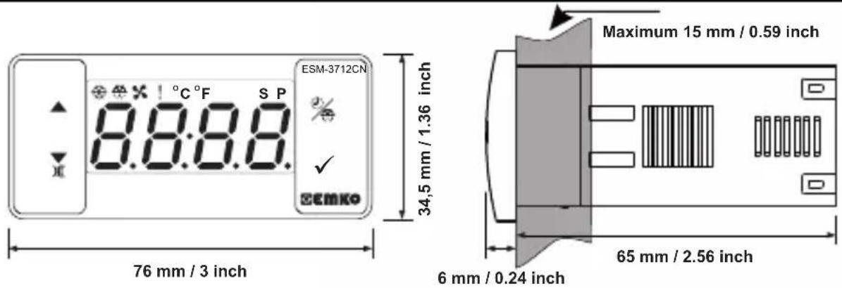
| Dimensions (Housing) | 76 x 34.5 x 71 mm |
| Panel Cutout | 71 x 29 mm |
| Weight | Approximately 0.2 kg |
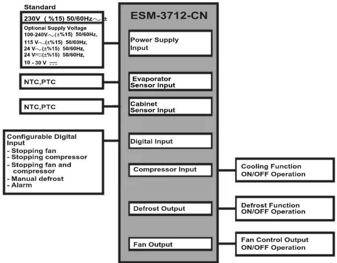
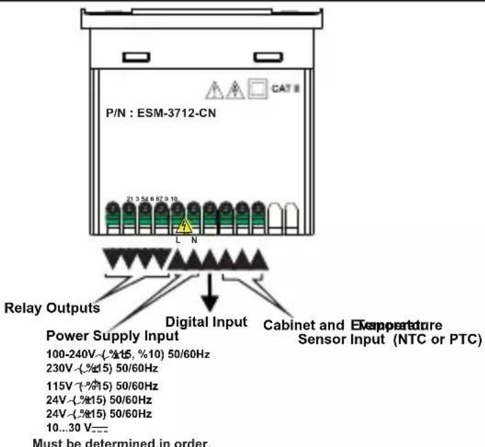
| Power Supply | 100-240 V~ (±15%, +10%) 50/60 Hz, 2.5 VA (other options available: 24 V~, 115 V~, 230 V~, 10-30 V---) |
| Sensor Input Type | NTC (10 kΩ at 25°C) or PTC (1000 Ω at 25°C) |
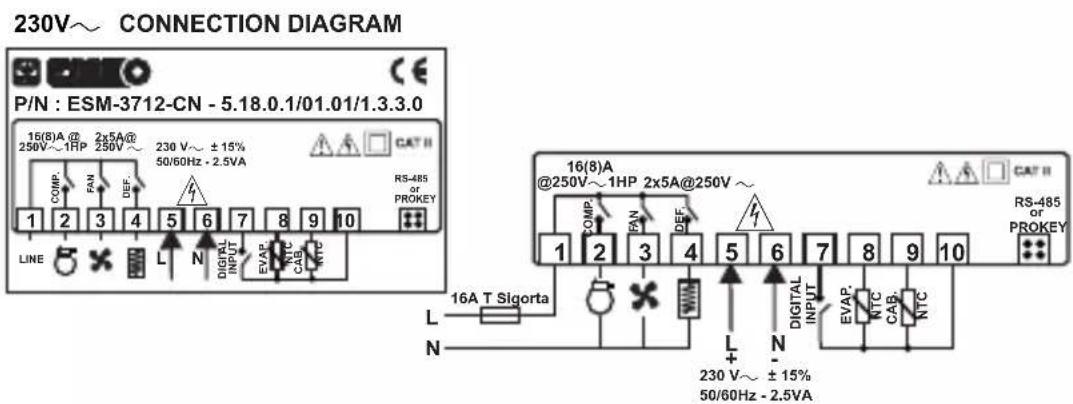
| Number of Relay Outputs | 3 (compressor, defrost, fan) |
| Compressor Output | 16 (8) A @ 250 V~, resistive load |
| Defrost Output | 5 A @ 250 V~, resistive load |
| Fan Output | 5 A @ 250 V~, resistive load |
| Display | 4-digit red LED (14 mm) |
| LED Indicators | S (green), P (green), °C (yellow), °F (yellow), Alarm (red), Defrost output (red), Fan output (red), Compressor output (red) |
| Internal Buzzer | ≥83 dB |
| Communication | Modbus RTU (RS-485) and ProKey |
| Operating Temperature | -30°C to +80°C |
| Operating Humidity | 90% RH max (non-condensing) |
| Protection Rating | IP65 (front), IP20 (rear), NEMA 4X |
| Housing Material | Plastic |
| Cleaning | With a cloth moistened with ethyl alcohol or water; do not use hydrocarbon-based solvents |
| Warranty | 2 years from delivery date |
| Manufacturer | Emko Elektronik Sanayi ve Ticaret A.S., Bursa, Turkey |
| Standards | CE, EHC |
Frequently Asked Questions - ESM-3712-CN Emko
User questions about ESM-3712-CN Emko
0 question about this device. Answer the ones you know or ask your own.
Ask a new question about this device
Download the instructions for your Temperature Controller in PDF format for free! Find your manual ESM-3712-CN - Emko and take your electronic device back in hand. On this page are published all the documents necessary for the use of your device. ESM-3712-CN by Emko.
USER MANUAL ESM-3712-CN Emko
- 4 Digits Display
- NTC Input or PTC Input (Must be determined in order.)
- 3 output for compressor, defrost and fan controls
- 2 sensor input for cabinet and evaporator
- Configurable digital input
-ON/OFFControl - Separately adjustable 2 offset value for cabinet and evaporator sensor
- Set value boundaries
- Operation selection of compressor operate continuously, stops or operates periodically in case of cabinet probe defect
- Compressor protection delays
- Selectable defrost function (hot gas or electric)
- Adjustable defrost time from front panel
- Manual defrost from front panel
- Defrost parameters
- Alarm parameters
- Fan can be operated depending on compressor and defrost
- Fan can be operated depending on evaporator temperature or (cabinet - evaporator ) temperature
- Adjustable internal buzzer according to the defrost, cabinet prob defect and alarm status
- Defrost time and/or manual defrost and/or temperature set value protection
- Password protection for programming mode
- Installing parameters using Prokey
- Remote access, data collecting and controlling with Modbus RTU
- Having CE mark according to European Norms
1.Preface
ESM-3712-CN series cooling controllers are designed for controlling cooling process. They can be used in many applications with their easy-use, On / Off control form and defrost properties. Some application and application fields which they are used are below:
Application Fields
Food
Machine production industries
etc...
Applications
Refrigerators
Air Conditioning
Storages
Freezers
etc...
1.1 Environmental Ratings


Operating Temperature : -30 to 80 °C
Max. Operating Humidity : 90% Rh (non-condensing)
Altitude: Up to 2000 m.
Forbidden Conditions:
Corrosive atmosphere
Explosive atmosphere
Home applications (The unit is only for industrial applications)
1.2 General Specifications
1.3 Installation
A visual inspection of this product for possible damage occurred during shipment is recommended before installation.
It is your responsibility to ensure that qualified mechanical and electrical technicians install this product.
If there is danger of serious accident resulting from a failure or defect in this unit, power off the system and separate the electrical connection of the device from the system.
The unit is normally supplied without a power supply switch or a fuse. Use power switch and fuse as required.
Be sure to use the rated power supply voltage to protect the unit against damage and to prevent failure
Keep the power off until all of the wiring is completed so that electric shock and trouble with the unit can be prevented.
Never attempt to disassemble, modify or repair this unit. Tampering with the unit may results in malfunction, electric shock or fire.
Do not use the unit in combustible or explosive gaseous atmospheres.
During putting equipment in hole on the metal panel while mechanical installation some metal burrs can cause injury on hands, you must be careful.
Montage of the product on a system must be done with it's fixing clamps. Do not do the montage of the device with inappropriate fixing clamp. Be sure that device will not fall while doing the montage.
It is your responsibility if this equipment is used in a manner not specified in this instruction manual.
1.4 Warranty
EMKO Elektronik warrants that the equipment delivered is free from defects in material and workmanship. This warranty is provided for a period of two years. The warranty period starts from the delivery date. This warranty is in force if duty and responsibilities which are determined in warranty document and instruction manual performs by the customer completely.
1.5 Maintenance
Repairs should only be performed by trained and specialized personnel. Cut power to the device before accessing internal parts.
Do not clean the case with hydrocarbon-based solvents (Petrol, Trichlorethylene etc.). Use of these solvents can reduce the mechanical reliability of the device. Use a cloth dampened in ethyl alcohol or water to clean the external plastic case.
1.6 Manufacturer Company
Manufacturer Information:
Emko Elektronik Sanayi ve Ticaret A.S.
Bursa Organize Sanayi Bolgesi, (Fethiye OSB Mah.) Ali Osman Sonmez Bulvari,
- Sokak, No:3 16215 BURSA - TÜRKIYE
Phone:+902242611900 Fax:+902242611912
Repair and maintenance service information:
Emko Elektronik Sanayi ve Ticaret A.Ş.
Bursa Organize Sanayi Bolgesi, (Fethiye OSB Mah.) Ali Osman Sonmez Bulvari,
- Sokak, No:3 16215 BURSA - TÜRKIYE
Phone: +90 224 261 1900 Fax: +90 224 261 1912
2. General Description
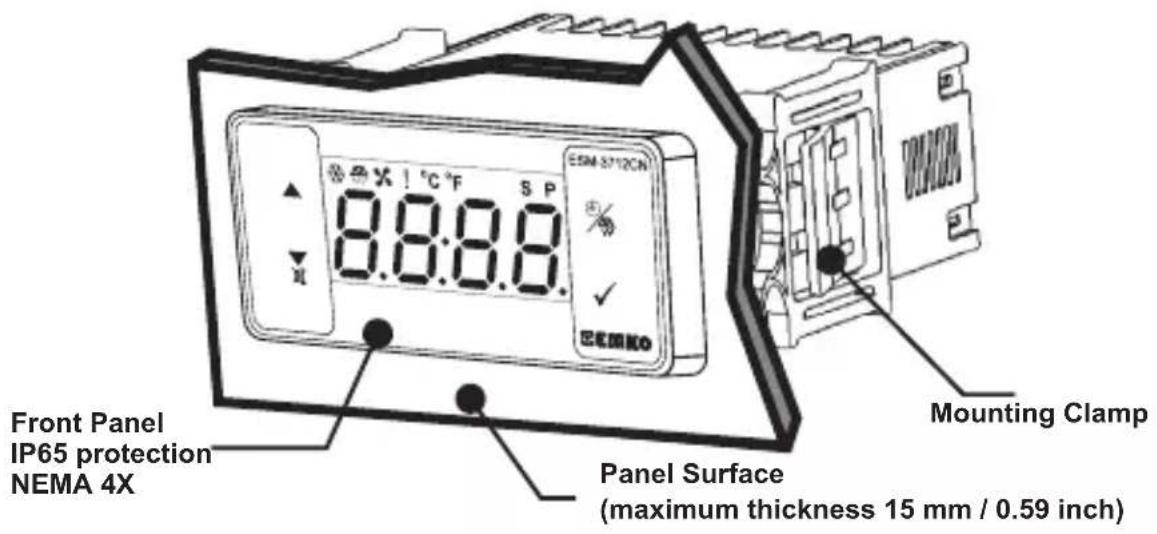
2.1 Front View and Dimensions of ESM-3712-CN Cooling Controller
2.2 Panel Cut-Out
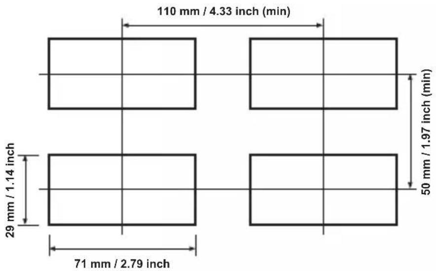
2.3 Panel Mounting and Removing
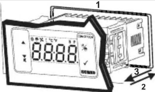
1-Before mounting the device in your panel, make sure that the cut-out is of the right size.
2-Insert the device through the cut-out. If the mounting clamps are on the unit, put out them before inserting the unit to the panel.
3- Insert the mounting clamps to the fixing sockets that located left and right sides of device and make the unit completely immobile within the panel
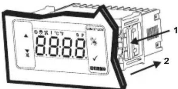
1-Pull mounting clamps from left and right fixing sockets.
2-Pull the unit through the front side of the panel
Before starting to remove the unit from panel, power off the unit and the related system.
3. Optimal Accessories
1.RS-485 Module
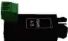
RS-485 Communication Interface
2.PROKEY Programming Module
The device is programmed (Upload or Download) by using the parameters.
3.1 Using Prokey
TO USE PROKEY, VALUE OF THE PrC PARAMETER MUST BE '0'.
IF PrC=1 AND BUTTON IS PRESSED ERRMESSAGE WILL BE SHOWN. 10s. LATER
DEVICE TURNS BACK TO THE MAIN OPERATION SCREEN OR YOU CAN PRESS SET BUTTON TO TURN BACK TO MAIN OPERATION SCREEN.
DOWNLOADING FROM DEVICE TO PROKEY
- The device is programmed by using parameters.
- Energize the device then put in PROKEY and press button. Message is shown on the display. When the loading has finished, message is shown.
- Press any button to turn back to main operation screen.
4.Remove the PROKEY.
NOTE: message is shown when an error occurs while programming. If you want to reload, put in PROKEY and press button. If you want to quit, remove PROKEY and press button. The device will turn back to main operation screen.
DOWNSLOADING FROM PROKEY TO DEVICE
-
Switch off the device.
2.Put in PROKEY then energize the device. -
When the device is energized, the parameter values in PROKEY, start downloading to the device automatically. At first, message is shown on the display, when loading has finished, end message is shown.
- After 10 second device starts to operate with new parameter values.
5.Remove the PROKEY.
NOTE: Err message is shown when an error occurs while programming. If you want to reload, switch off the device and put in PROKEY then energize the device. If you want to quit remove PROKEY and press button. The device will turn back to main operation screen.
4. Electrical Wiring Diagram
4.1 Supply Voltage Input Connection of the Device
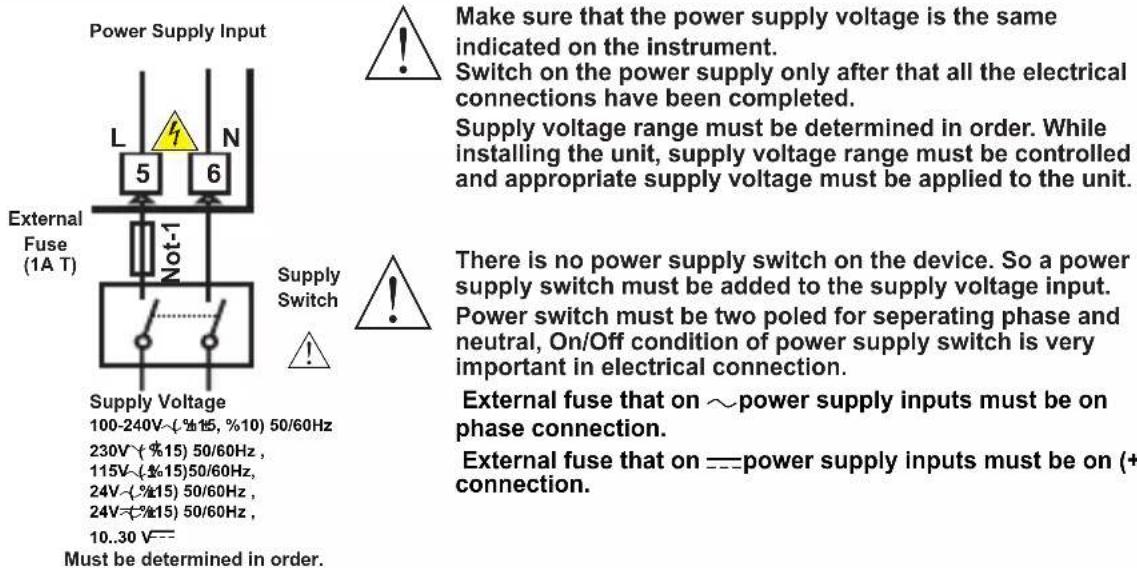
Note-1: External fuse is recommended.
Note-2 : Stranded cable cross section: 1,5 mm^2 ,Solid cable cross-section: 2,5 mm^2 The stripping length is 7 to 9mm.
Note-3 : Supply cables must comply with the requirements of IEC 60277 or IEC 60245
4.2 Device Label and Connection Diagram
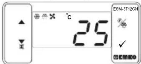
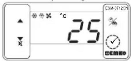
5.Front Panel Definition and Accessing to the Menus
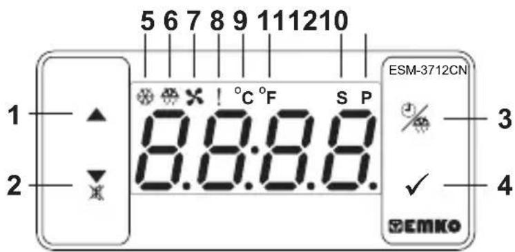
BUTTON DEFINITIONS
-
Increment Button :
In main operation screen, press this button to display evaporator sensor temperature.
It is used to increase the value in the Set screen, Defrost screen and Programming mode. -
Decrement, Silencing Buzzer and Downloading to Prokey Button :
** It is used to decrease the value in the Set screen, Defrost screen and Programming mode.
It is used to silence the buzzer.
If Prc = 0 , it is used to download from device to prokey.
- Defrost Button :
** In the main operation screen; if this button pressed, defrost time value will be displayed.
**In the main operation screen; if this button pressed for 3 seconds, manual defrost starts.
- Set Button :
** In the main operation screen; if this button pressed, set value will be displayed. Value can be changed using increment and decrement buttons. When Set button pressed again, value is saved and returns back to main operating screen.
** To access the programming screen; in the main operation screen, press this button for 5 seconds.
** It is used to saving value in the Set screen, Defrost screen and programming screen.
LED DEFINITIONS
- Compressor output led :
** This led indicates that compressor output is active. If any of compressor protection time active, this led blinks
6.Defrost output led :
** This led indicates that defrost output is active.
Blinks once in a second while Defrost delay time.
Blinks (5 Hz) while entering Defrost time value.
7.Fan output led :
** This led indicates that fan output is active.
** Blinks once in a second while Fan delay time.
8.Alarm led :
** It is active when low alarm and high alarm statuses.
9.Celcius led :
** Indicates that device is in °C mode.
10.Fahrenheit led :
** Indicates that device is in °F mode.
11.Set led :
Indicates that device is in Set value changing mode.
12.Program led :
Blinks once in a second in programming mode.
6. Changing and Saving Temperature Set Value
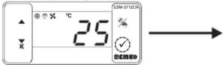
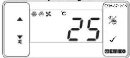
Main Operating Screen
When SET button pressed "S" led will be active and temperature set value will be displayed.
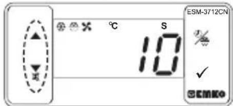
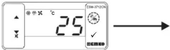
SET Value Screen
Temperature set value can be changed with increment and decrement buttons.
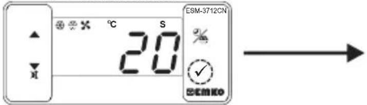
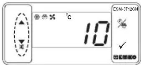
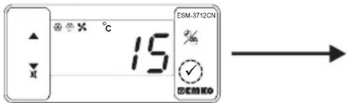
SET Value Screen
When SET button pressed temperature set value can be saved.
Main Operating Screen
"S" will be inactive and goes back to main operation screen.
Temperature set value parameter (Default=10) MODBUS ADDRESS:40001
Temperature set value, can be programmed between minimum temperature set value Su1 and maximum temperature set value SuH .
6.1 Changing and Saving Defrost Time Set Value
Main Operating Screen
When defrost button is pressed, defrost time set value is shown and defrost output led starts to fast blink (5 Hz).
Defrost Time Value Screen
Change the defrost time set value with increment and decrement buttons.
Defrost Time Value Screen
Press set button for saving the defrost time set value
Main Operating Screen
Defrost time set value is saved, defrost output led stop the fast blink (5 Hz), main operation screen is shown.

If no operation is performed in defrost time set value changing mode and temperature set value changing mode for 20 seconds, device turns to main operation screen automatically.
6.2 Programming Mode Parameter List
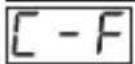
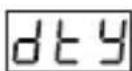
Temperature Unit Selection Parameter (Default = 0) MODBUS ADDRESS:40002

°C selected.
°F selected.

Decimal Seperator Enabling Parameter (Default = 0) MODBUS ADDRESS:40003
Disable. Enable.
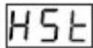
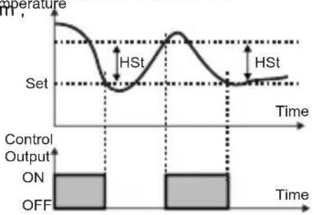
Hysteresis Parameter for Compressor Output (Default = 1) MODBUS ADDRESS:40004
from 1 to 20^ for NTC (-50^, 100^) or PTC (-50^, 150^) from 1 to 36^ for NTC (-58^, 212^) or PTC (-58^, 302^) from 0.1 to 10.0^ for NTC (-50.0^, 100.0^) or PTC (-50.0^, 150.0^) from 0.1 to 18.0^ for NTC (-58.0^, 212.0^) or PTC (-58.0^, 302.0^)
In ON/OFF control algorithm temperature value is tried to keep equal to set value by opening or closing the last control element. ON/OFF controlled system, temperature value oscillates continuously. Temperature value's oscillation period or amplitude around set value changes according to controlled system. For reducing oscillation period of temperature value, a threshold zone is formed below or around set value and this zone is named hysteresis.

Minimum Temperature Set Value Parameter(Default = Minimum Value of Device Scale) MODBUS ADDRESS:40005
Temperature set value can not be lower than this value. This parameter value can be adjusted from minimum value of device scale to maximum temperature set value parameter & H
Maximum Temperature Set Value Parameter (Default = Maximum Value of Device Scale) MODBUS ADDRESS:40006
Temperature set value can not be greater than this value.
This parameter value can be adjusted from minimum temperature set value parameter to maximum value of the device scale.
Cabinet Sensor Offset Parameter (Default = 0) MODBUS ADDRESS:40007
From -20 to 20^ for NTC(-50°C, 100°C) or PTC(-50°C, 150°C),
From -36 to 36^ for NTC(-58°F, 212°F) or PTC(-58°F, 302°F),
From -10.0 to 10.0^ for NTC(-50.0°C, 100.0°C) or PTC(-50.0°C, 150.0°C),
From -18.0 to 18.0^ for NTC(-58.0°F, 212.0°F) or PTC(-58.0°F, 302.0°F).
Evaporator Sensor Selection Parameter (Default =1) MODBUS ADDRESS:40008

Evaporator sensor is inactive.
Evaporator sensor is active.

Evaporator Sensor Offset Parameter (Default = 0) MODBUS ADDRESS:40009
If evaporator sensor selection parameter [525] is 1, then this parameter is observed.
From -20 to 20^ for NTC(-50°C, 100°C) or PTC(-50°C, 150°C),
From -36 to 36^ for NTC(-58°F, 212°F) or PTC(-58°F, 302°F),
From -10.0 to 10.0^ for NTC(-50.0°C, 100.0°C) or PTC(-50.0°C, 150.0°C),
From -18.0 to 18.0^ for NTC(-58.0°F,212.0°F) or PTC(-58.0°F,302.0°F).
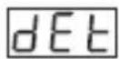
Defrost Type Selection Parameter (Default =0) MODBUS ADDRESS:40010
Electric defrost.
Hot gas defrost.
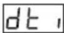
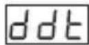
Defrost Time Parameter(Default = 10 )MODBUS ADDRESS:40011
It can be adjusted from 0 to 999 minutes.
If it is selected 0 automatic or manual defrost is not performed.
Defrost Repeat Cycle Parameter (Default = 1) MODBUS ADDRESS:40012
It can be adjusted from 1 to 99 hours.

Defrost Stopping Temperature Parameter (Default = 2°C) MODBUS ADDRESS:40013
For evaporator sensor selection parameter 525 is 1 (evaporator sensor is active), while defrost operation, if evaporator temperature reaches to temperature that defined at this parameter in a shorter time than dt parameter, then defrost operation stops.

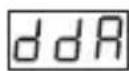
Defrost at Power On Selection and Defrost Delay Parameter (Default = no) MODBUS ADDRESS:40014
It can be adjust from 0 to 99 minutes. When tihs parameter is 0, if decrement button is pressed, n o is observed. In this condition system goes through a defrost cycle at the end of the defrost repeat cycle time after power on.If this parameter value is between 0 and 99, then system goes through a defrost cycle at the end of the this parameter time after power on.
Display Status During Defrost Parameter (Default = 3) MODDBUS ADRESS:40015
The cabinet temperature value is displayed during defrost.
Cabinet temperature value at the start of the defrost is displayed during defrost.
Temperature set value is displayed during defrost.
is displayed to indicate the defrost is in progress.

Displaying Current Temperature Delay After Defrost Parameter (Default = 0) MODDBUS ADRESS:40016
This parameter defines the delay for displaying current temperature being active after defrost. It can be adjusted from 0 to 255 minutes.
Dripping Time Parameter (Default = 2) MODBUS ADDRESS:40017
This parameter defines for dripping time after defrost. It can be adjusted from 0 to 15 minutes.

Temperature Alarm Delay After Dripping Parameter (Default = 0) MODBUS ADDRESS:40018
This parameter defines the delay for temperature alarm being active after dripping time completion. It can be adjusted from 0 to 15 minutes.

Compressor Start Delay at Power On Parameter (Default = 0) MODBUS ADDRESS:40019
When power is first applied to the device, This time delay must be expired for activation of compressor. It can be adjusted from 0 to 20 minutes.

Compressor Start-Start Delay Parameter (Default = 0) MODBUS ADDRESS:40020
This time delay must be expired between two activation of the compressor. It can be adjusted from 0 to 20 minutes.
Minimum Compressor OFF Time Parameter (Default = 0)MODBUS ADDREDS:40021 When compressor is inactive, this time delay must be expired for activation of the compressor. It can be adjusted from 0 to 20 minutes.
Minimum Compressor ON Time Parameter (Default = 0) MODBUS ADRES:40022 When compressor is active, this time delay must be expired for deactivation of the compressor. It can be adjusted from 0 to 20 minutes.

Cabinet Probe Defect Parameter (Default = 0) MODBUS ADDRESS:40023
Compressor is OFF in case of cabinet probe defect.
Compressor is ON in case of cabinet probe defect.
Compressor operates periodically according to Pon and PoF time periods in case of cabinet probe defect.

Compressor Active Time in Case of Cabinet Probe Defect Parameter (Default = 0) MODBUS ADDRESS:40024
If cabinet probe defect parameter P_df is 2, then this parameter is observed. It can be adjusted from 99 minutes.

Compressor Inactive Time in Case of Cabinet Probe Defect Parameter (Default = 0) MODBUS ADDRESS:40025
If cabinet probe defect parameter |P_dF| is 2, then this parameter is observed. It can be adjusted from L_dF to 99 minutes.
Temperature Alarm Function Selection Parameter (Default = 0) MODBUS ADRES:40026

Temperature alarm function is inactive.
Absolute alarm is selected. If temperature lower than Aol and higher than HvH , then alarm is on.

Relative alarm is selected. Alarm operates according to the set value. If cabinet temperature value is below (Set -RUL) or above (Set +Huh), alarm occurs.

Temperature Alarm Minimum Parameter (Default = Minimum Value of Device Scale) MODBUS ADRES:40027
For = 1 , this parameter value can be adjusted from minimum value of device scale to temperature alarm maximum parametervalue.For = 2 , this parameter value can be adjusted O to %50 of the device scale.
Temperature Alarm Maximum Parameter (Default = Maximum Value of Device Scale) MODBUS ADRES:40028
For RLS = 1 , this parameter value can be adjusted from temperature alarm minimum parameter R_L value to maximum value of device scale. For RLS = 2 , this parameter value is can be adjusted 0 to %50 of the device scale.
Temperature Alarm On Delay Time Parameter(Default = 0) MODBUS ADDRESS:40029
Temperature Alarm On Delay Time can be defined with this parameter. It can be adjusted from 0 to 99 minutes.

Temperature Alarm Delay After Power On Parameter(Default = 0) MODBUS ADDRESS:40030
When power is first applied to the device, this time delay must be expired for activation of temperature alarm. It can be adjusted from 0 to 99 minutes.

Fan Operation Selection Parameter (Default = 1) MODBUS ADDRESS:40031
Fan is OFF.
Fan is ON.
Fan operates according to the evaporator sensor temperature value.
Fan operates according to the ( cabinet - evaporator ) temperature value.

Fan Stopping Temperature Parameter(Default = 2°C) MODBUS ADDRESS:40032 Fan stopping temperature can be defined with this parameter. It can be adjusted from minimum value to maximum value of device scale.
Hsyteresis Parameter for Fan Output (Default = 1) MODBUS ADDRESS:40033 From 1 to 20^ for NTC (-50^, 100^) , from 1 to 36^ for NTC (-58^, 212^) , from 0.1 to 10.0^ for NTC (-50.0^, 100.0^) , from 0.1 to 18.0^ for NTC (-58.0^, 212.0^)

Fan Activity Selection According to the Compressor and Defrost (Default = 0) MODBUS ADDRESS:40034
Fan operates according to the parameter.
Fan operates according to the E S parameter, but fan is stopped if compressor is stops.

Fan operates according to the parameter, but fan is stopped during defrost and dripping time.
Fan operates according to the parameter.If compressor stops, during defrost and dripping operations fan stops.
Fan Delay Time After Completion of Dripping Time Parameter (Default = 2) MODBUS ADDRESS:40035
Fan Delay Time After Completion of Dripping Time is defined with this parameter. It can be adjusted from 0 to 15 minutes.

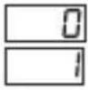
Digital Input Contact Selection Parameter (Default = 1) MODBUS ADDRESS:40036
Digital input is inactive.
NO "normally open" digital input is active when the contact is closed.
NC "normally close" digital input is active when the contact is opened.
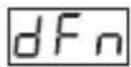
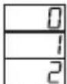
Digital Input Function Selection Parameter (Default = 0) MODBUS ADDRESS:40037 If digital input contact selection parameter value = 0 , this parameter is not observed.
When the digital input is active, fan is stopped. screen will be displayed.
When the digital input is active, compressor is stopped. screen will be displayed and defrost operation will be disabled. If Buzzer function selection parameter buf = 2 or 4 buzzer is active.

When the digital input is active, first fan stops, 10 seconds later compressor stops. l will be displayed at main operation screen.
When the digital input is active, defrost starts.

When the digital input is active, alarm will be active. H will be displayed at main operation screen. If Buzzer function selection parameter b = 2 or 4 buzzer is active.
Digital Input Effect Time Parameter (Default = - - ) MODBUS ADDRESS:40038
If digital input contact selection parameter value dct = 0 , this parameter is not observed. For digital input function selection parameter dfn = 0 or 2, maximum effect time of digital input is determined with this parameter. It can be adjusted from 0 to 120 minutes. When this parameter is 0, if decrement button is pressed, is observed. In this condition the effect will be ended when digital input is deactive.

Buzzer Function Selection Parameter (Default = 0) MODBUS ADDRESS:40039
Buzzer is inactive.
Buzzer is active during defrost operation.
Buzzer is active if an alarm occurs.
Buzzer is active during cabinet sensor failures.
Buzzer is active during defrost, alarm or cabinet sensor failures.
Buzzer Active Time (Default = - - - ) MODBUS ADDRESS:40040
If buzzer function selection parameter value bw = 0 , this parameter is not observed. Buzzer active time can be define with this parameter. It can be adjusted from 1 to 99 minutes. When this parameter is 1, if decrement button is pressed, is observed. In this condition buzzer is active till buzzer silence button is pressed.
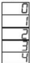
Button Protection Parameter (Default = 0) MODBUS ADDRESS:40041
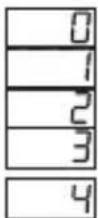
There is no protection.
Defrost time set value can not be changed and manual defrost is not available.
Temperature set value can not be changed.
Defrost time set value and temperature set value can not be changed and manual defrost is not available.
Defrost time can not be changed, Defrost ON/OFF operation is available.
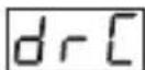
Communication Mode Selection Parameter( Default = 0 ) MODBUS ADRESS:40042

PROKEY communication selected.
RS485 communication selected.

Slave ID Parameter (Default = 1) MODBUS ADDRESS=40043
Device communication address parameter (1 to 247).

Programming Mode Accessing Password (Default = 0) MODBUS ADDRESS:40044
It is used for accessing to programming mode. It can be adjusted from 0 to 999. If it is 0, password is not entered for accessing to the parameters. If password is '12' only, can be accessible.
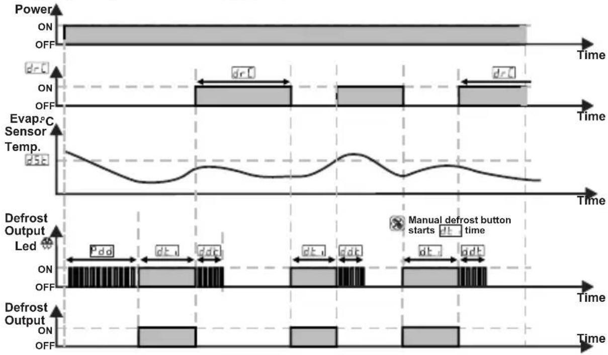
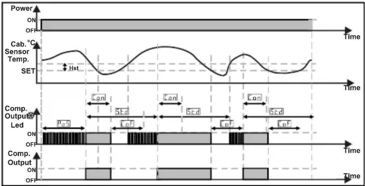
6.3 Operation Graphics of ESM-3712-CN Cooling Controller
1- Defrost time parameter value ≥ 1 Defrost repeat cycle parameter value ≥ 1 Defrost at power on selection and defrost delay parameter value ≥ 1 Dripping time parameter value ≥ 1
2- Compressor start delay at power on parameter value PoS ≥ 1 ,
Compressor start - start delay parameter value Std ≥ 1 ,
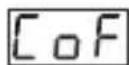
Minimum compressor OFF time parameter value CoF ≥ 1 ,
Minimum compressor ON time parameter value Con ≥ 1 ;
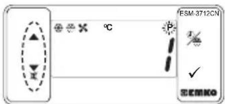
6.4 Entering To The Programming Mode, Changing and Saving Parameter Main Operating Screen
When SET button is pressed for 5 seconds, "P" led starts to blink. If programming mode entering password is different from 0, programming mode entering screen will be observed.
Note1: If programming mode accessing password is 0, Temperature Unit Selection Screen is observed instead of programming screen accessing password
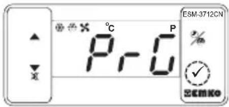
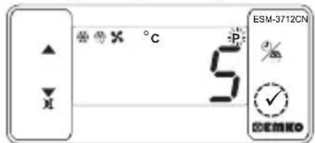
Programming Mode Entering Screen
Press SET button for accessing to the password entering screen.
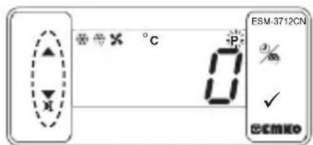
Password Entering Screen
Enter programming mode accessing password with increment and decrement buttons.
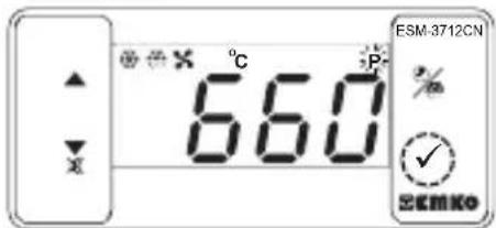
Password Entering Screen Press SET/OK button for entering the password.
Note-2: If programming mode accessing password is 0 parameter values can be seen. But parameter values can not be changed.
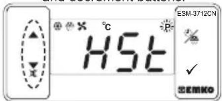
Programming Screen
Press SET button for accessing to the parameter value. Press increment button for accessing to the next parameter, press decrement button for accessing to the previous parameter
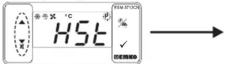
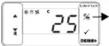
Compressor Output Hysteresis Parameter Value
Change the value with increment and decrement buttons.
Compressor Output Hysteresis Parameter Value
Press set button for saving the parameter.
Compressor Output Hysteresis Parameter
Press increment button for accessing to the next parameter, press decrement button for accessing to the previous parameter

If no operation is performed in programming mode for 20 seconds, device turns to main operation screen automatically..
7. Failure Messages in ESM-3712-CN Cooling Controller
1-5b1 message blinking.Cabinet temperature sensor failure ensor connection is wrong or there is no sensor connection. While this message shown on this display, if buzzer function selection parameter buF is 3 or 4, internal buzzer starts to operate.
7. Failure Messages in ESM-3712-CN Cooling Controller
2-56b2 message blinking.
Evaporator temperature sensor failure. sensor connection is wrong or there is no sensor connection.
3- message blinking.
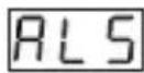
For absolute alarm, if cabinet temperature sensor value is lower than temperature alarm minimum parameter R_UL value and for relative alarm, if cabinet temperature sensor value is lower than (Temperature Set - R_UL ), then AL message starts to blink. If buzzer function selection parameter is 2 or 4, internal buzzer starts to operate.
4- message blinking.
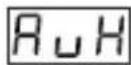
For absolute alarm, if cabinet temperature sensor value is higher than temperature alarm maximum parameter RuH value and for relative alarm, if cabinet temperature sensor value is higher than (Temperature Set +RuH ), then RH message starts to blink. If buzzer function selection parameter b_uF is 2 or 4, internal buzzer starts to operate.
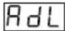
5- Rd, message blinking.
When the digital input is active and digital input function selection parameter value dF_n is 0 or 2, message starts to blink.
6- [B, n] message blinking.
When the digital input is active and digital input function selection parameter value is 1 or 4 message starts to blink. If buzzer function selection parameter is 2 or 4, internal buzzer starts to operate.
8. Manual Defrost Operation with Defrost Button
3 sn.
While defrost time parameter value ≥ 1 button protection parameter value P_rt = 0 or 2 and defrost output is inactive, in main operation screen if defrost button is pressed for 3 seconds manual defrost will be active
8.1 Manual Defrost Operation with Digital Input
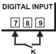
While digital input function selection parameter value = 3 if digital input contact selection parameter value = 1 (normally open NO) and the K switch is getting closed, or if digital input contact selection parameter value = 2 (normally close NC) and the K switch is getting opened manual defrost will be active
9.Modbus Adresses of Device Status Parameters (Read Input Register)
MODBUS ADRES:30001
MODBUS ADRES:30002
MODBUSADRES:30003
Cabinet Temperature Value
Evaporator Temperature Value
MODBUS ADRES:30004
Led Status : 0.bit°C Led, 4.bit Fan Led, 5.bit Defrost Led, 6.bit Compressor Led, 7.bit Alarm Led 13.bit Programming Led. 14.bit Set Led
Device Status : 0.bit Alarm Status, 1.bit Buzer Status
MODBUS ADRES:30005
2.bit Cabinet Sensor Lost Status, 3.bit Evaporator Sensor Lost Status
7.bit Defrost Status
Output Status: 0.bit Compressor O
1.bit Defrost Output
2.bit Fan Output
MODBUS ADRES:30006
Device Type and Version
10. Specifications
Protection Against
Mechanical Impacts : 1 Joule (IK06)
Device Type : Cooling Controller
Housing&Mounting : 76 mm x 34.5 mm x71 mm plastic housing for panel
Panel cut-out is 71 × 29 ~mm
Protection Class
:NEMA 4X (IP65 at front, IP20 at rear)
10. Specifications
Weight
Environmental Ratings
Storage / Operating Temperature
Storage / Operating Humidity
Installation
Overvoltage Category
Pollution Degree
Operating Conditions
Supply Voltage and Power
Temperature Sensor Inputs
NTC Input Type or PTC Input Type
Accuracy
Sensor Break Protection
Sampling Cycle
Control Form
Relay Outputs
Display
LED
Internal Buzzer
Approvals
Approximately 0.2Kg
: Standard, indoor at an altitude of less than 2000 meters with none condensing humidity.
-40°C to +85°C / -30°C to +80°C
: 90 % max. (None condensing)
: Fixed installation
:II.
: II, office or workplace, none conductive pollution
: Continuous
:100-240V~(%15, +%10) 50/60Hz - 2.5VA
:230V~(%15)50/60Hz-2.5VA
:115V~(±%15)50/60Hz-2.5VA
:24V~(%15)50/60Hz-2.5VA
:24V\~(±%15)50/60Hz-2.5VA,10-30V---2.5W
:NTC or PTC
:NTC (10 kΩ @25 °C) or PTC (1000 Ω @25 °C)
: ±1 % of full scale for thermoresistance
: Upscale
: 3 samples per second
:ON/OFF
: 16(8) A@250 V ~ at resistive load(Compressor Output)
5 A@250 V ~ at resistive load(Defrost and Fan Output)
: 14 mm Red 4 digit LED Display
: S (Green), P (Green), C (Yellow), F(Yellow), Alarm(Red), Defrost Output (Red), Fan Output (Red) Compressor Output (Red),
:≥83dB

11. Ordering Information
| ESM-3712-CN (T7x35 DIN Size) | A B C D E F G H I J K L U V W Z | |
| Supply VoltageA | ||
| 1 | 100-240V~(-%15, +%10) 50/60Hz - 2.5VA | |
| 2 | 24V~±%15) 50/60Hz - 2.5VA | |
| 3 | 24V~ (±%15) 50/60Hz - 2.5VA | |
| 4 | 115V~ (±%15) 50/60Hz - 2.5VA | |
| 5 | 230V~ (±%15) 50/60Hz - 2.5VA | |
| 8 | 10 - 30 V ---2.5W | |
| 9 | Customer | |
| BC | Input Type | Scale(°C) |
| 12 | PTC (Note-1) | -50°C/-58°F;150°C/302°F |
| 18 | NTC (Note-1) | -50°C/-58°F;100°C/212°F |
| E | Compressor Output | |
| 1 | Relay Output (16(8) A@250 V~at resistive load, 1 NO) | |
| FG | Defrost Output | |
| 01 | Relay Output (5 A@250 V~at resistive load, 1 NO) | |
| Fan OutputHl | ||
| 01 | Relay Output (5 A@250 V~at resistive load, 1 NO) | |
| V | Temp. Sensor which is given with ESM-3712-CN | |
| 0 | None | |
| 1 | PTC-M6L40.K1.5 (PTC Air Probe with 1.5 mt silicon cable) | |
| 2 | PTCS-M6L30.K1.5.1/8" (PTC Liquid Probe with1.5 mt silicon cable) | |
| 3 | NTC-M5L20.K1.5 (NTC Sensor, thermoplastic moulded with 1.5 m cable for cooling application) | |
| 4 | NTC-M6L50.K1.5 (NTC Sensor, stainless steel housing with 1.5 m cable for cooling application) | |
| 9 | Customer | |
All order information of ESM-3712-CN Cooling Controller are given on the table at left. User may form appropriate device configuration from information and codes that at the table and convert it to the ordering codes.
Firstly, supply voltage then other specifications must be determined. Please fill the order code blanks according to your needs.
Please contact us, if your needs are out of the standards.
Note-1: If input type is selected PTC or NTC (BC= 12, 18), Temperature sensor is given with the device. For this reason, if input type is selected as PTC, sensor type (V = 0,1 or 2) or if input type is selected as NTC, sensor type (V =0,3 or 4) must be declared in ordering information.

$$ \begin{array}{r c l} \sim & \Rightarrow \text {V a c}, \ \hline \hline \hline \hline \hline \hline \hline \hline \hline \hline \hline \hline \hline \hline \hline \hline \hline \hline \hline \hline \hline \hline \hline \hline \hline \hline \hline \hline \hline \hline \hline \hline \hline \hline & \Rightarrow \text {V d c} \end{array} $$
$$ \Rightarrow \mathrm {V d c} \text {o r V a c} \text {c a n b e a p p l i e d} \sim $$
EMKO
Your Technology Partner
Thank you very much for your preference to use Emko Elektronik products, please visit our web page to download detailed user manual.
www.emkoelektronik.com.tr

Atmosphere corrosive
Remarque-3: Supply cables must comply with the requirements of IEC 60277 or IEC 60245
Désactiver.
Activer.

Note-3: Supply cables must comply with the requirements of IEC 60277 or IEC 60245