
DUS158 - Pressure washer MAKITA - Free user manual and instructions
Find the device manual for free DUS158 MAKITA in PDF.

| Product type | Cordless pressure sprayer |
| Brand | Makita |
| Model | DUS158 |
| Intended use | Spraying household and garden products (water, pesticides, herbicides, fertilizers) |
| Power source | 18 V lithium-ion battery (compatible BL1820B, BL1830B, BL1840B, BL1850B, BL1860B) |
| Tank capacity | 15 L |
| Max. working pressure | 0.5 MPa |
| Flow rate with vertical nozzle | Approximately 0.90 L/min |
| Hose length | 1.7 m |
| Lance length | 60 cm |
| Dimensions (L × W × H) | 317 × 237 × 517 mm |
| Empty weight | 5.9 - 6.2 kg |
| Full weight | 20.9 - 21.2 kg |
| Sound level (L_pA) | 70 dB(A) or less |
| Vibration level (a_h) | 2.5 m/s² or less |
| Continuous lock function | Yes, for spraying without holding the lever |
| Included nozzles | Vertical 2-head nozzle and weed killer nozzle |
| Tank material | Chemical-resistant plastic |
| Maintenance | Rinse the tank after each use; clean the nozzle with a wire; purge the pump if necessary |
| Safety | Automatic shut-off in case of overload; short-circuit protection; use PPE (goggles, gloves, mask) |
| Warranty | Makita manufacturer's warranty (refer to the manual) |
| Spare parts | Available from Makita authorized centers (battery, charger, nozzles, seals) |
Frequently Asked Questions - DUS158 MAKITA
User questions about DUS158 MAKITA
0 question about this device. Answer the ones you know or ask your own.
Ask a new question about this device
Download the instructions for your Pressure washer in PDF format for free! Find your manual DUS158 - MAKITA and take your electronic device back in hand. On this page are published all the documents necessary for the use of your device. DUS158 by MAKITA.
USER MANUAL DUS158 MAKITA
English (Original instructions)
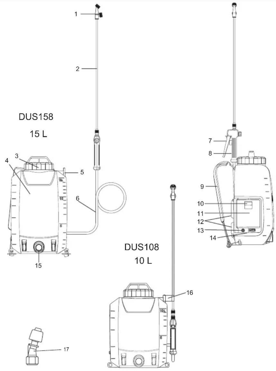
| 1 | Vertical type 2-head nozzle 2 Spray | wand 3 Tank lid 4 Tank | (10 | L/15 L) | ||
| 5 | Spray wand holder 6 Spray hose 7 | Lever 8 Handle | ||||
| 9 | Carrying straps 10 Locking lever 11 | Battery cover 12 Back cushion | ||||
| 13 | ON/OFF switch 14 Indicator lamps | 15 Liquid outlet | 16 | Hook (for attaching the spray wand) | ||
| 17 | Weedkiller nozzle | - | - | - | - | - |
SPECIFICATIONS
| Model DUS108 DUS158 | ||
| Rated voltage D.C. 18 V | ||
| Tank capacity 10 L 15 L | ||
| Hose length 1.7 m | ||
| Spray wand length 60 cm | ||
| Max. working pressure 0.5 MPa | ||
| Working pressure with vertical type 2-head nozzle | Approx. 0.34 MPa | |
| Flow rate with vertical type 2-head nozzle | Approx. 0.90 L/min | |
| Working pressure with weedkiller nozzle | Approx. 0.12 MPa | |
| Flow rate with weedkiller nozzle Approx. 1.70 L/min | ||
| Nozzle fitting screw G 1/4" | ||
| Technical the volume of total residual ≤ 200 ml | ||
| Dimensions (L × W × H) 317 × 237 × 437 mm 317 × 237 × 517 mm | ||
| Weight when empty 5.6 - 5.9 kg 5.9 - 6.2 kg | ||
| Weight when full | 15.6 - 15.9 kg | 20.9 - 21.2 kg |
- Due to our continuing program of research and development, the specifications herein are subject to change without notice.
- Specifications may differ from country to country.
- The weight may differ depending on the attachment(s), including the battery cartridge. The lightest and heaviest combination, according to EPTA-Procedure 01/2014, are shown in the table.
Applicable battery cartridge and charger
| Battery cartridge | BL1820B / BL1830B / BL1840B / BL1850B / BL1860B |
| Charger | DC18RC / DC18RD / DC18RE / DC18SD / DC18SE / DC18SF / DC18SH |
• Some of the battery cartridges and chargers listed above may not be available depending on your region of residence.
⚠ WARNING: Only use the battery cartridges and chargers listed above. Use of any other battery cartridges and chargers may cause injury and/or fire.
WARNING: Do not use a corded power supply such as battery adapter or portable power pack with this machine. The cable of such power supply may hinder the operation and result in personal injury.
Symbols
The followings are symbols used for the equipment. Be sure that you understand their meaning before use.
 | Wear ear protection. |  | Warning |
 | Wear a breathing mask. |  | Wear eye protection. |
 | Wear safety footwear. |  | Wear protective gloves. |
 | Do not use in the rain or leave the sprayer outdoors while raining. | ||
 | Read instruction manual. | ||
 | Keep bystanderds away when spraying. | ||
Intended use
This machine is intended for spraying.
Noise
The typical A-weighted noise level determined according to EN62841-1:
Sound pressure level ( L_pA ): 70 dB (A) or less
Uncertainty (K) : 3 dB (A)
NOTE: The declared noise emission value(s) has been measured in accordance with a standard test method and may be used for comparing one tool with another.
NOTE: The declared noise emission value(s) may also be used in a preliminary assessment of exposure.

WARNING: Wear ear protection.

WARNING: The noise emission during actual
use of the power tool can differ from the declared value(s) depending on the ways in which the tool is used especially what kind of workpiece is processed.

WARNING: Be sure to identify safety measures to protect the operator that are based on animation of exposure in the actual conditions of the (taking account of all parts of the operating cycle such as the times when the tool is switched and when it is running idle in addition to the longer time).
Vibration
The vibration total value (tri-axial vector sum) determined according to EN62841-1:
Work mode: operation without load
Vibration emission (a_h):2.5m / s^2 or less
Uncertainty (K) : 1.5 m/s²
NOTE: The declared vibration total value(s) has been measured in accordance with a standard test method and may be used for comparing one tool with another.
NOTE: The declared vibration total value(s) may also be used in a preliminary assessment of exposure.

WARNING: The vibration emission during
actual use of the power tool can differ from the declared value(s) depending on the ways in which the tool is used especially what kind of workpiece is processed.

WARNING: Be sure to identify safety measures to protect the operator that are based on animation of exposure in the actual conditions of time (taking account of all parts of the operating cycle such as the times when the tool is switched and when it is running idle in addition to the longer time).
EC Declaration of Conformity
For European countries only
The EC declaration of conformity is included as Annex A to this instruction manual.
WARNING
This appliance can be used by children aged from 8 years and above and persons with reduced physical, sensory or mental capabilities or lack of experience and knowledge if they have been given supervision or instruction concerning use of the appliance in a safe way and understand the hazards involved. Children shall not play with the appliance. Cleaning and user maintenance shall not be made by children without supervision.
General power tool safety warnings

WARNING: Read all safety warnings, instruc-
tions, illustrations and specifications provided with this power tool. Failure to follow all instructions listed below may result in electric shock, fire and/or serious injury.
Save all warnings and instructions for future reference.
The term “power tool” in the warnings refers to your mains-operated (corded) power tool or battery-operated (cordless) power tool.
Work area safety
- Keep work area clean and well lit. Cluttered or dark areas invite accidents.
- Do not operate power tools in explosive atmospheres, such as in the presence of ammable liquids , gases or dust. Power tools create sparks which may ignite the dust or fumes.
- Keep children and bystanders away while operating a power tool. Distractions can cause you to lose control.
Electrical safety
- Power tool plugs must match the outlet. Never modify the plug in any way. Do not use any adapter plugs with earthed (grounded) power tools. Unmodified plugs and matching outlets will reduce risk of electric shock.
- Avoid body contact with earthed or grounded surfaces, such as pipes, radiators, ranges and refrigerators. There is an increased risk of electric shock if your body is earthed or grounded.
- Do not expose power tools to rain or wet conditions. Water entering a power tool will increase the risk of electric shock.
- Do not abuse the cord. Never use the cord for carrying, pulling or unplugging the power tool. Keep cord away from heat, oil, sharp edges or moving parts. Damaged or entangled cords increase the risk of electric shock.
- When operating a power tool outdoors, use an extension cord suitable for outdoor use. Use of a cord suitable for outdoor use reduces the risk of electric shock.
- If operating a power tool in a damp location is unavoidable, use a residual current device (RCD) protected supply. Use of an RCD reduces the risk of electric shock.
- Power tools can produce electromagnetic fields (EMF) that are not harmful to the user. However, users of pacemakers and other similar medical devices should contact the maker of their device and/or doctor for advice before operating this power tool.
Personal safety
- Stay alert, watch what you are doing and use common sense when operating a power tool. Do not use a power tool while you are tired or under the influence of drugs, alcohol or medication. A moment of inattention while operating power tools may result in serious personal injury.
- Use personal protective equipment. Always wear eye protection. Protective equipment such as a dust mask, non-skid safety shoes, hard hat or hearing protection used for appropriate conditions will reduce personal injuries.
- Prevent unintentional starting. Ensure the switch is in the off-position before connecting to power source and/or battery pack, picking up or carrying the tool. Carrying power tools with your finger on the switch or energising power tools that have the switch on invites accidents.
- Remove any adjusting key or wrench before turning the power tool on. A wrench or a key left attached to a rotating part of the power tool may result in personal injury.
-
Do not overreach. Keep proper footing and balance at all times. This enables better control of the power tool in unexpected situations.
-
Dress properly. Do not wear loose clothing or jewellery. Keep your hair and clothing away from moving parts. Loose clothes, jewellery or long hair can be caught in moving parts.
- If devices are provided for the connection of dust extraction and collection facilities, ensure these are connected and properly used. Use of dust collection can reduce dust-related hazards.
- Do not let familiarity gained from frequent use of tools allow you to become complacent and ignore tool safety principles. A careless action can cause severe injury within a fraction of a second.
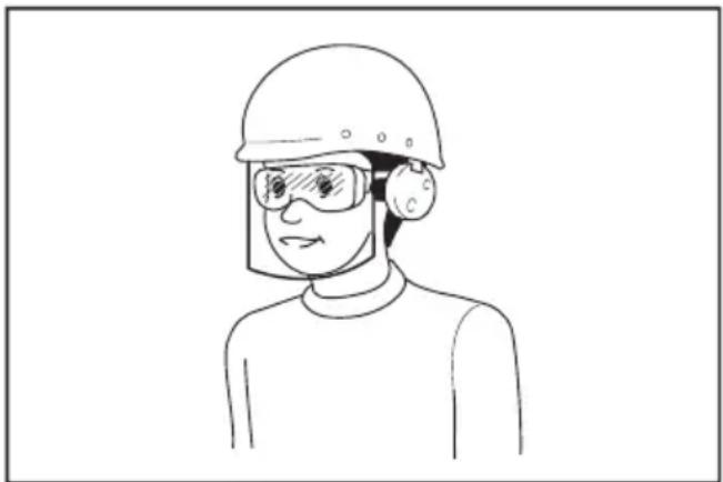
- Always wear protective goggles to protect your eyes from injury when using power tools. The goggles must comply with ANSI Z87.1 in the USA, EN 166 in Europe, or AS/NZS 1336 in Australia/New Zealand. In Australia/New Zealand, it is legally required to wear a face shield to protect your face, too.
natural_image
Line drawing of a person wearing a helmet and safety goggles (no text or symbols)It is an employer's responsibility to enforce the use of appropriate safety protective equipments by the tool operators and by other persons in the immediate working area.
Power tool use and care
- Do not force the power tool. Use the correct power tool for your application. The correct power tool will do the job better and safer at the rate for which it was designed.
- Do not use the power tool if the switch does not turn it on and off. Any power tool that cannot be controlled with the switch is dangerous and must be repaired.
- Disconnect the plug from the power source and/or remove the battery pack, if detachable, from the power tool before making any adjustments, changing accessories, or storing power tools. Such preventive safety measures reduce the risk of starting the power tool accidentally.
-
Store idle power tools out of the reach of children and do not allow persons unfamiliar with the power tool or these instructions to operate the power tool. Power tools are dangerous in the hands of untrained users.
-
Maintain power tools and accessories. Check for misalignment or binding of moving parts, breakage of parts and any other condition that may affect the power tool's operation. If damaged, have the power tool repaired before use. Many accidents are caused by poorly maintained power tools.
- Keep cutting tools sharp and clean. Properly maintained cutting tools with sharp cutting edges are less likely to bind and are easier to control.
- Use the power tool, accessories and tool bits etc. in accordance with these instructions, taking into account the working conditions and the work to be performed. Use of the power tool for operations different from those intended could result in a hazardous situation.
- Keep handles and grasping surfaces dry, clean and free from oil and grease. Slippery handles and grasping surfaces do not allow for safe handling and control of the tool in unexpected situations.
- When using the tool, do not wear cloth work gloves which may be entangled. The entanglement of cloth work gloves in the moving parts may result in personal injury.
Battery tool use and care
- Recharge only with the charger specified by the manufacturer. A charger that is suitable for one type of battery pack may create a risk of fire when used with another battery pack.
- Use power tools only with specifically designated battery packs. Use of any other battery packs may create a risk of injury and fire.
- When battery pack is not in use, keep it away from other metal objects, like paper clips, coins, keys, nails, screws or other small metal objects, that can make a connection from one terminal to another. Shorting the battery terminals together may cause burns or a fire.
- Under abusive conditions, liquid may be ejected from the battery; avoid contact. If contact accidentally occurs, flush with water. If liquid contacts eyes, additionally seek medical help. Liquid ejected from the battery may cause irritation or burns.
- Do not use a battery pack or tool that is damaged or modified. Damaged or modified batteries may exhibit unpredictable behaviour resulting in fire, explosion or risk of injury.
- Do not expose a battery pack or tool to fire or excessive temperature. Exposure to fire or temperature above 130 °C may cause explosion.
- Follow all charging instructions and do not charge the battery pack or tool outside the temperature range specified in the instructions.
Charging improperly or at temperatures outside the specified range may damage the battery and increase the risk of fire.
Service
- Have your power tool serviced by a qualified repair person using only identical replacement parts. This will ensure that the safety of the power tool is maintained.
- Never service damaged battery packs. Service of battery packs should only be performed by the manufacturer or authorized service providers.
- Follow instruction for lubricating and changing accessories.
Cordless Garden Sprayer Safety Warnings
WARNING: Risk of fire or explosion. Do not spray flammable liquids such as gasoline. Look for this symbol reference on the container.
WARNING: Some spray created from products used with the sprayer contains chemicals known to cause cancer, birth defect of other reproductive harm.
Some examples of these chemicals are:
· compounds in fertilize.
- compounds in insecticides, herbicides, and pesticides; arsenic and chromium from chemically treated lumber. Follow directions on containers of all such products. To reduce your exposure to these chemicals, wear approved safety equipment such as face masks that are specially designed to filter out sprays, gloves, and other appropriate protective equipment.
■ Before using any pesticide or other spray materials in this sprayer, read the label on its original container thoroughly and follow its directions. Some spray materials are dangerous and should not be used in this sprayer, as they can damage the sprayer and cause serious bodily injury or property damage.
■ Electric shock hazard. Never spray toward electrical outlets.
■ Do not use commercial grade chemicals or chemicals for commercial or industrial purposes. Use only consumer grade water-based lawn and garden chemicals.
■ Do not pour hot or boiling liquids into the tank. These can weaken or damage the hose or tank.
■ Spray area must be well ventilated.
■ Avoid spraying on windy days. Spray can be accidentally blown onto plants or objects that should not be sprayed.
■ Store the sprayer in a secure, well-ventilated indoor space with the fluid tank empty.
■ Do not use caustic (alkali) self-heating or corrosive (acid) liquids in this sprayer. These can corrode metal parts or weaken the tank and hose.
■ Wear respiratory protection and appropriate protective clothing. Keep bystanders away when spraying.
- Know the contents of the chemical being sprayed. Read all Material Safety Data Sheets (MSDS) and container labels provided with the chemical. Follow the chemical manufacturer's safety instructions.
■ Do not leave residue or spray material in the tank after using the sprayer. Clean after each use.
■ Do not smoke while using the sprayer, or spray where spark or flame is present.
■ Risk of injection. Do not discharge directly against skin.
■ To reduce the risk of electric shock, do not put the sprayer into water or other liquid. Do not place or store the sprayer where it can fall or be pulled into a tub or sink. - Maintain this product. Thoroughly inspect both the inside and outside of the sprayer and examine the components before each use. Check for cracked and deteriorated hoses, leaks, clogged nozzles, and missing or damaged parts. If damaged, have the product repaired before use. Many accidents are caused by poorly maintained products.
■ Disconnect the battery from the unit before draining, cleaning, or storing the sprayer. Such preventive safety measures reduce the risk of accidental starting.
■ Always wear eye protection with side shields or goggles marked to comply with ANSI Z87.1. Failure to do so could result in fluids entering your eyes resulting in possible serious injury.
■ Protect your lungs. Wear a face or dust mask when using the sprayer. Following this rule will reduce the risk of serious personal injury.
■ Battery tools do not have to be plugged into an electrical outlet; therefore, they are always in operating condition. Be aware of possible hazards when not using your battery tool or when changing accessories. Remove battery pack when tool is not in use. Following this rule will reduce the risk of electric shock, fire, or serious personal injury.
■ Do not place battery tools or their batteries near fire or heat. This will reduce the risk of explosion and possibly injury. - Do not crush, drop or damage battery pack. Do not use a battery pack or charger that has been dropped or received a sharp blow. A damaged battery is subject to explosion. Properly dispose of a dropped or damaged battery immediately.
■ Batteries can explode in the presence of a source of ignition, such as a pilot light. To reduce the risk of serious personal injury, never use any cordless product in the presence of open flame. An exploded battery can propel debris and chemicals. If exposed, flush with water immediately.
■ Do not charge battery tool in a damp or wet location. Following this rule will reduce the risk of electric shock.
■ For best results, your battery tool should be charged in a location where the temperature is more than 10 °C (50 °F) but less than 40 °C (104 °F). To reduce the risk of serious personal injury, do not store outside or in vehicles.
■ Under extreme usage or temperature conditions, battery leakage may occur. If liquid comes in contact with your skin, wash immediately with soap and water. If liquid gets into your eyes, flush them with clean water for at least 10 minutes, then seek immediate medical attention. Following this rule will reduce the risk of serious personal injury.
■ Do not use battery-operated appliance in rain.
■ Exercise care in handling batteries in order not to short the battery with conducting materials such as rings, bracelets, and keys. The battery or conductor may overheat and cause burns.
- Do not dispose of the battery(ies) in a fire. The cell may explode. Check with local codes for possible special disposal instructions.
■ Do not open or mutilate the battery(ies).
Released electrolyte is corrosive and may cause damage to the eyes or skin. It may be toxic if swallowed.
- Avoid Dangerous Environment - Don't use appliances in damp or wet locations.
■ Use Right Appliance - Do not use appliance for any job except that for which it is intended.
- Don’t Force Appliance - It will do the job better and with less likelihood of a risk of injury at the rate for which it was designed.
■ Store Idle Appliances Indoors - When not in use, appliances should be stored indoors in dry, and high or locked-up place - out of reach of children.
■ Maintain Appliance With Care - Keep clean for best performance and to reduce the risk of injury. Follow instructions for changing accessories. Inspect appliance cord, and if damaged, have it repaired by an authorized service facility. Keep handles dry, clean, and free from oil and grease.
- Check Damaged Parts - Before further use of the appliance, a guard or other part that is damaged should be carefully checked to determine that it will operate properly and perform its intended function. Check for alignment of moving parts, binding of moving parts, breakage of parts, mounting, and any other condition that may affect its operation. A guard or other part that is damaged should be properly repaired or replaced by an authorized service center unless indicated elsewhere in this manual.
- Don't topple a filled-up tank to avoid leak in case tank lid is not tightened.
Residual risks
Even if you use this electric power tool in accordance with instructions, certain residual risks cannot be rules out. The following hazards may arise in connection with the equipment's construction and layout:
- Lung damage if no suitable protective mask is used.
- Contact with hazardous substances. Spray materials can be harmful if inhaled or swallowed or if allowed to come into contact with the skin or eyes. Follow the instructions and wear suitable protective equipment.
Important safety instructions for battery cartridge
- Before using battery cartridge, read all instructions and cautionary markings on (1) battery charger, (2) battery, and (3) product using battery.
- Do not disassemble or tamper the battery cartridge. It may result in a fire, excessive heat, or explosion.
- If operating time has become excessively shorter, stop operating immediately. It may result in a risk of overheating, possible burns and even an explosion.
- If electrolyte gets into your eyes, rinse them out with clear water and seek medical attention right away. It may result in loss of your eyesight.
- Do not short the battery cartridge:
(1) Do not touch the terminals with any conductive material.
(2) Avoid storing battery cartridge in a container with other metal objects such as nails, coins, etc.
(3) Do not expose battery cartridge to water or rain.
A battery short can cause a large current flow, overheating, possible burns and even a breakdown.
- Do not store and use the tool and battery cartridge in locations where the temperature may reach or exceed 50 °C (122 °F).
- Do not incinerate the battery cartridge even if it is severely damaged or is completely worn out. The battery cartridge can explode in a fire.
- Do not nail, cut, crush, throw, drop the battery cartridge, or hit against a hard object to the battery cartridge. Such conduct may result in a fire, excessive heat, or explosion.
- Do not use a damaged battery.
- The contained lithium-ion batteries are subject to the Dangerous Goods Legislation requirements.
For commercial transports e.g. by third parties, forwarding agents, special requirement on packaging and labeling must be observed.
For preparation of the item being shipped, consulting an expert for hazardous material is required.
Please also observe possibly more detailed national regulations.
Tape or mask off open contacts and pack up the battery in such a manner that it cannot move around in the packaging.
- When disposing the battery cartridge, remove it from the tool and dispose of it in a safe place. Follow your local regulations relating to disposal of battery.
- Use the batteries only with the products specified by Makita. Installing the batteries to non-compliant products may result in a fire, excessive heat, explosion, or leak of electrolyte.
- If the tool is not used for a long period of time, the battery must be removed from the tool.
- During and after use, the battery cartridge may take on heat which can cause burns or low temperature burns. Pay attention to the handling of hot battery cartridges.
- Do not touch the terminal of the tool immediately after use as it may get hot enough to cause burns.
- Do not allow chips, dust, or soil stuck into the terminals, holes, and grooves of the battery cartridge. It may result in poor performance or breakdown of the tool or battery cartridge.
- Unless the tool supports the use near high-voltage electrical power lines, do not use the battery cartridge near high-voltage electrical power lines. It may result in a malfunction or breakdown of the tool or battery cartridge.
- Keep the battery away from children.
SAVE THESE INSTRUCTIONS.
CAUTION: Only use genuine Makita batteries. Use of non-genuine Makita batteries, or batteries that have been altered, may result in the battery bursting causing fires, personal injury and damage. It will also void the Makita warranty for the Makita tool and charger.
Tips for maintaining maximum battery life
- Charge the battery cartridge before completely discharged. Always stop tool operation and charge the battery cartridge when you notice less tool power.
- Never recharge a fully charged battery cartridge. Overcharging shortens the battery service life.
- Charge the battery cartridge with room temperature at 10 °C - 40 °C ( 50 °F - 104 °F ). Let a hot battery cartridge cool down before charging it.
- When not using the battery cartridge, remove it from the tool or the charger.
- Charge the battery cartridge if you do not use it for a long period (more than six months).
CORDLESS GARDEN SPRAYER USE AND CARE
- The cordless garden sprayer can work by Makita lithium-ion battery cartridge. Use of any other batteries may create a risk of fire. Recharge batteries only with the specified charger. A charger that may be suitable for one type of battery may create a risk of fire when used with another battery.
- When inserting or removing the battery, always place the cordless garden sprayer on a flat and stable surface.
- Do not use any batteries, attachments or accessories not recommended by the manufacturer of this appliance. The use of batteries, attachments or accessories not recommended can result in serious personal injury.
Intended use
This pressure sprayer is designed exclusively for spraying the following solutions outdoors and in well ventilated greenhouses.
Water
- Pesticides
- Weedkillers
- Natural oils dissolved in water (e.g..neem oil, rapeseed oil).
• Fertilizers dissolved in water.
Liquids to be sprayed, particularly natural oils dissolved in water, must have a water-like consistency. Liquids of greater viscosity cannot be sprayed, or only with lesser power.
Only liquid fertilizers, weedkillers and pesticides that are approved by the local licensing authority in the country of use may be sprayed. At the time of manufacture, no harmful effects on the materials used are known to be caused by these approved substances or natural oils dissolved in water. The fertilizers, pesticides and weedkillers are only allowed to be sprayed in the concentrations specified by the manufacturer of the spray solutions. If in doubt, please contact the relevant manufacturer.
The pressure sprayer is not designed to be used with foodstuffs or to spray liquids that exceed the maximum permitted operating temperature of 40 °C . Similarly, it is prohibited to spray acidic, caustic and flammable liquids whose flash point is below 55 °C , as well as impregnating agents, disinfectant, paints, varnishes, grease, glazes and synthetically manufactured oils.

Important! Atomized flammable liquids with a flash point in excess of 55 ^ are also highly combustible.
Never use the pressure sprayer
- as a flame gun.
• for storing liquids.
• for substances with unknown risk.
The equipment is to be used only for its prescribed purpose. Any other use is deemed to be a case of misuse. The user / operator and not the manufacturer will be liable for any damage or injuries of any kind caused as a result of this.
ASSEMBLY

CAUTION:
Always be sure that the machine is switched off and the battery cartridge is removed before carrying out any work on the machine.

CAUTION:
Make sure that the all parts are securely assembled so that the liquid does not leak when operating the machine.
Assembly of the spray wand
Note: The items such as nozzles and cup are included in the tank.
- Remove the cap from the handle.
- Make sure the O-ring is in place, then thread the spray wand onto the handle and tighten it securely. Refer to Figure 1.
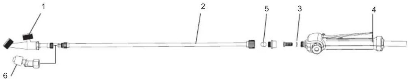
| 1 Vertical type 2-head Nozzle 2 Spray | wand 3 O-ring | ||
| 4 Handle 5 Cap 6 Weedkiller nozzle |
Figure 1
Carrying strap
Attach the carrying strap to the hangers of the machine and fastening hooks for the belt in position.
Slip the belt over your shoulders and adjust the length of the belt. After that, fasten the belt so that you can work without fatigue.
To adjust belt length, pull on the two ends of the belt to shorten it or on the two belt release mechanisms to extend it. Refer to Figure 2.
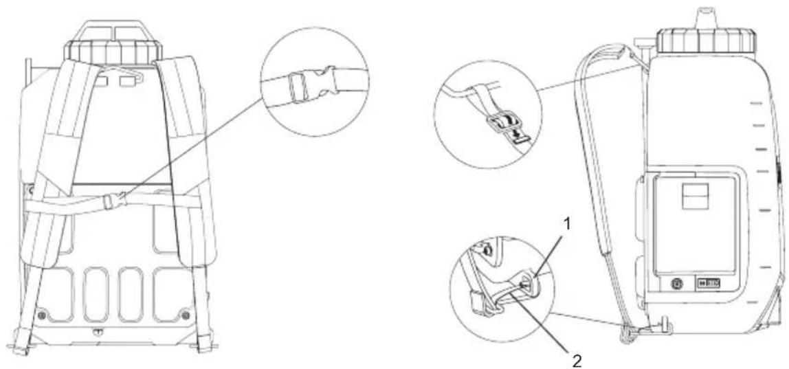

Figure 2
FUNCTIONAL DESCRIPTION

CAUTION:
Always be sure that the machine is switched off and the battery cartridge is removed before adjusting or checking function on the machine.
Installing or removing the battery cartridge

CAUTION:
• Always switch off the machine before installing or removing of the battery cartridge.
- Hold the machine and the battery cartridge firmly when installing or removing battery cartridge. Failure to hold the machine and the battery cartridge firmly may cause them to slip off your hands and result in damage to the machine and battery cartridge and a personal injury.
- Do not use force when installing the battery cartridge. If the cartridge does not slide in easily, it is not being inserted correctly.
• Always install the battery cartridge fully until the red indicator cannot be seen. If not it may accidentally fall out of the tool causing injury to you or someone around you.
- Be careful not to pinch your fingers when opening or closing the battery cover.
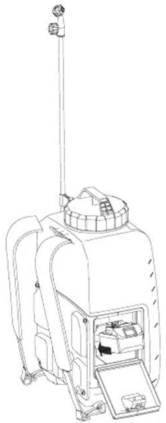
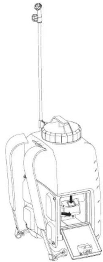
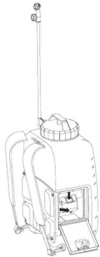
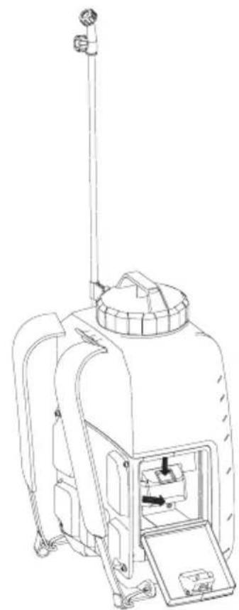
To install the battery cartridge, pull down the locking lever, and then open the battery cover. Align the tongue on the battery cartridge with the groove in the housing and slip it into place. Always insert it all the way until it locks in place with a little click. Refer to Figure 3.
To remove the battery cartridge, slide it from the machine while pressing the button. Refer to Figure 4.
natural_image
Line drawing of a mechanical device with internal components and a vertical pole (no text or symbols)Figure 3 Figure 4
natural_image
Line drawing of a portable air purifier with attached fan and control panel (no text or symbols)Indicating the residual battery capacity
Press the check button on the machine to indicate residual battery capacity. The indicator lamps light up for few seconds. Refer to Figure 5.
| Indicator lamps | Residual battery capacity | |
 | Off | |
 | 50 % to 100 % | |
 | 30 % to 50 % | |
 | 0 % to 30 % | |
NOTE:
- Depending on the conditions of use and the ambient temperature, the indication may differ slightly from the actual capacity.
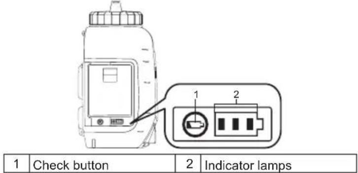
Figure 5
Machine / battery protection system
The machine is equipped with the protection system. This system automatically cuts off power to the motor to extend machine and battery life. The machine will automatically stop during operation if the machine or battery is placed under one of the following conditions.
- Overload protection: When the machine is operated in a manner that causes it to draw an abnormally high current, the machine automatically stops without any indication. In this situation, turn the machine off and stop the application that caused the machine to become overloaded. Then turn the machine on to restart.
- Overdischarge protection: When the battery capacity becomes low, the machine stops automatically. If the machine does not operate even when the switches are operated, remove the battery cartridge from the machine and charge it.
Indicating the remaining battery capacity
Only for battery cartridges with the indicator
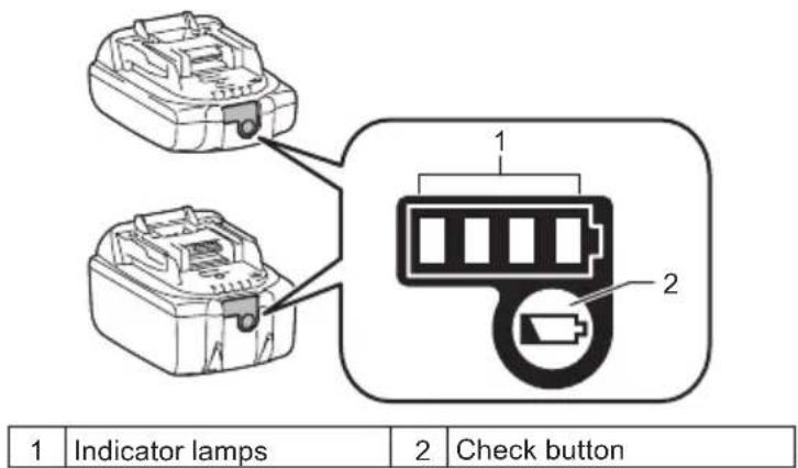
Figure 6
12 English
Press the check button on the battery cartridge to indicate the remaining battery capacity. The indicator lamps light up for a few seconds.
| Indicator lamps | Remaining capacity | ||
| Lighted Off B | inking | ||
 | 75 % to 100 % | ||
 | 50 % to 75 % | ||
 | 25 % to 50 % | ||
 | 0 % to 25 % | ||
 | Charge the battery. | ||
  | The battery may have malfunctioned. | ||
NOTE: Depending on the conditions of use and the ambient temperature, the indication may differ slightly from the actual capacity.
NOTE: The first (far left) indicator lamp will blink when the battery protection system works.
Mixture

WARNING! Always follow the chemical manufacturer's instructions printed on their product labeling for use, cleaning, and storage. Clean thoroughly after each use, following the instructions in the Maintenance and cleaning section of this manual. Chemicals should be stored out of the reach of children. Failure to do so may result in serious personal injury.

WARNING! THE PRODUCT IS DESIGNED FOR SPRAYING CONSUMER-GRADE HOME AND GARDEN CHEMICALS SUCH AS WEED KILLERS, FUNGICIDES, INSECTICIDES, AND FERTILIZERS.

CAUTION: Be sure that no previously used chemical has been left in tank. If so, chemical reaction may occur generating harmful gas.

NOTICE: Do not over fill the tank. Doing so may damage the machine.

NOTICE: Liquids to be sprayed must be as thin as water. Thicker liquids will not spray properly.
- Remove the battery prior to adding chemical liquid to the tank.
- Remove the tank lid. Refer to Figure 7.
- Measure the recommended liquid. The cup can be used to measure up to 200 ml (8 oz). Refer to Figure 8.
- Carefully pour the liquid into the tank with measuring cup through the filling opening of the tank. You can also dissolve chemical liquid in water completely in a separate container and then pour it into the tank. Make sure that the tank filling strainer is in place. Refer to Figure 9.
- Tighten the tank lid. Refer to Figure 10.
- Rinse the measuring cup with clean water.
*Container is not included.
Figure 7 Figure 8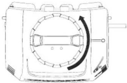 | 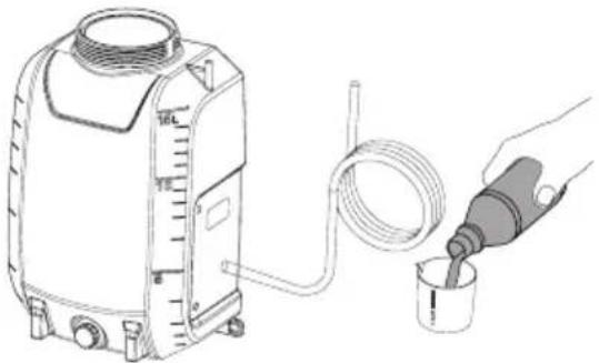 |
Figure 9 Figure 10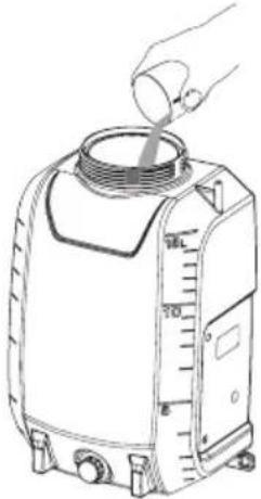 | 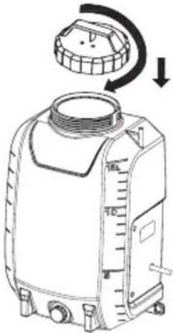 |
OPERATION

WARNING! Risk of fire or explosion. Spray area must be well-ventilated and away from sparks or flames.

WARNING! The liquid outlet nut must be tightened securely throughout the operation.

WARNING! Make sure that the carrying strap is not loose or detached before operation.

CAUTION:
When operating the machine, be sure to put on the carrying strap firmly.
Turning the machine on/off
- Before operating the machine, put on safety goggles and other safety gear.
- Press the On/off switch to start the machine.
- Press and hold the lever down to start spraying. Refer to Figure 11.
- Release the lever to stop spraying.
- Press the On/off switch to turn off the machine.
Lock-on
The lock-on feature is convenient for continuous spray or when covering a large area.
-
To lock-on, press the lever down and pull the lock button backwards, then release the lever. Refer to Figure 12.
-
To release the lock-on, press the lever and push the lock button forward.
Note: Make sure the lever is not in locked position before inserting the battery pack into the machine.
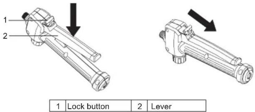
Figure 11 Figure 12
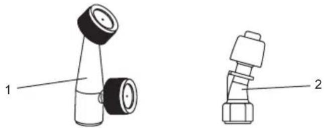
Attaching a nozzle
Two nozzles are provided with the cordless garden sprayer. Thread the nozzle onto the end of the spray wand. Please use only original replacement nozzle.
natural_image
Technical line drawing of two mechanical components labeled 1 and 2, showing different assembly shapes (no text or symbols present)| 1 | Vertical type 2-head nozzle | 2 | Weedkiller nozzle |
Figure 13
Spraying

WARNING! Never set the unit on the ground during use. Avoid the machine and battery from getting wet at all times. Do not spray near or directly at the unit.
- Aim the sprayer nozzle directly at the plants or objects you wish to spray.
- Never point the spray end of the wand at yourself or others.
- Be aware of splash back, stand far enough from the object being sprayed to prevent the spray splashing back onto you
- Never spray in the direction of people or animals; always spray downwind.
- Avoid spraying on windy days. Spray can be accidentally blown onto plants or objects that should not be sprayed.
- Be aware of the volume application rate and check the the volume in the tank from time to time.
MAINTENANCE AND CLEANING

CAUTION:
Always be sure that the machine is switched off and the battery cartridge is removed before attempting to perform inspection or maintenance.
To maintain product SAFETY and RELIABILITY, repairs, any other maintenance or adjustment should be performed by Makita Authorized or Factory Service Centers, always using Makita replacement parts.
MAINTENANCE

WARNING! To avoid serious personal injury, always remove the battery pack from the machine when cleaning or performing any maintenance.

WARNING! Always wear eye protection with side shields or goggles marked to comply with ANSI Z87.1. Failure to do so could result in fluids entering your eyes resulting in possible serious injury.

WARNING! When servicing, use only identical replacement parts. Use of any other parts may create a hazard or cause product damage.

WARNING! Do not at any time let brake fluids, gasoline, penetrating oils, etc., come in contact with plastic parts. Chemicals can damage, weaken, or destroy plastic which may result in serious personal injury.

NOTICE: Periodically inspect the entire product for damaged, missing, or loose parts such as screws, nuts, bolts, caps, etc. Tighten securely all fasteners and caps and do not operate this product until all missing or damaged parts are replaced. Please contact customer service or a qualified service center for assistance.

NOTICE: Never use gasoline, benzine, thinner, alcohol or the like. Discoloration, deformation or cracks may result.
GENERAL MAINTENANCE: Avoid using solvents when cleaning plastic parts. Most plastics are susceptible to damage from various types of commercial solvents and may be damaged by their use. Use clean clothes to remove dirt, dust, oil, grease, etc. Unless stipulated otherwise, we recommend that you arrange for the qualified technician to check the equipment every 2 years.
CLEANING THE UNIT

WARNING! Always store and dispose of chemicals properly. Disposal of contaminated rinse water should be performed according to local ordinances and by laws.
DRAINING THE TANK
If there is any liquid left in the tank after spraying, the tank should be drained before cleaning.
- Remove the battery pack.
- Drain the contents through the fill area and the liquid outlet.
NOTE: Make sure that the O-ring inside the liquid outlet cap is in place.
NOTE: Drain the liquid back into the original container. Do not store chemical liquid in the tank.
CLEANING THE TANK
- Fill the tank about one-third full with clean water. A small amount of mild household detergent may be added.
NOTE: Never use flammable chemicals or abrasive cleaning agents to clean the tank.
- Wipe the outside of the tank with a clean, dry cloth.
- Reinstall the battery pack. Spray until the tank has been emptied. Make sure to direct the spray toward an area that will not be damaged by the spray solution.
- Refill and repeat the procedure with clean water. It may be necessary to rinse the tank more than once, then drain again as instructed above.
- Allow all parts to completely dry before reinstalling parts and storing the unit.
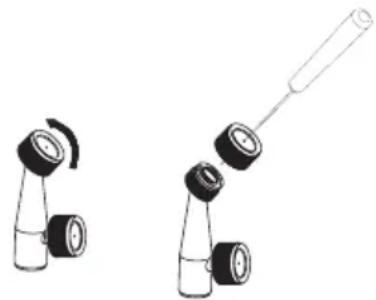
CLEANING THE NOZZLE
If the nozzle becomes plugged, use the steps below to clear.
- Remove the battery pack.
- Loosen and remove the nozzle from spray wand.
- Push a small wire through the exposed holes to clear any debris. Then flush with clean water. Refer to Figure 14
natural_image
Two diagrams showing a bottle with a handle and a smaller bottle with a spiral, both without any text or symbols.Figure 14
CLEANING THE PUMP
If the sprayer cannot draw the fluid from tank or it cannot spray out liquid at the first use or after long-term storage. Follow the procedures below to clean the pump:
- Switch off the machine and remove the battery.
- Remove the spray wand from handle.
- Drain any remaining liquid or store leftover liquid to another container to make sure the tank is empty.
- Unscrew the red cap to open water inlet hole, and then connect the hole to the water tap. Make sure the O-ring is placed inside the red cap. Refer to Figure 15.
- Open the water tap slowly and press down the lever at the same time to allow water flush away any debris adhered to the pump. Refer to Figure 16.
- Disconnect the water tap and re-tighten the red cap. Make sure that the O-ring inside the cap is in place.
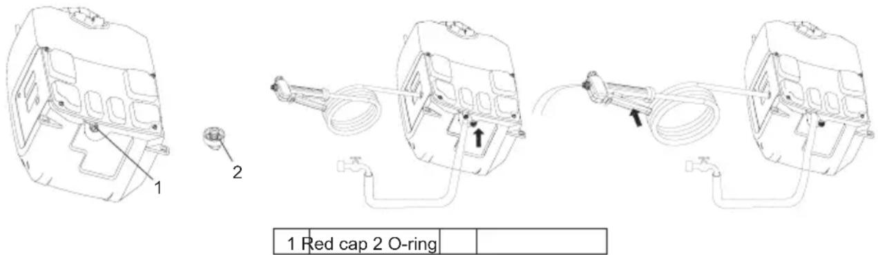
Figure 15 Figure 16
OPTIONAL ACCESSORIES

CAUTION:
These accessories or attachments are recommended for use with your Makita product specified in this manual. The use of any other accessories or attachments might present a risk of injury to persons. Only use accessory or attachment for its stated purpose.
If you need any assistance for more details regarding these accessories, ask your local Makita Service Center.
- Makita genuine battery and charger.
NOTE:
- Some items in the list may be included in the product package as standard accessories. They may differ from country to country.
Français (Instructions originales)

natural_image
Line drawing of a person wearing a helmet and safety goggles (no text or symbols)1 Cintre 2 Crochets de fixation
Figure 2
DESCRIPTION FONCTIONNELLE

AVERTISSEMENT :
natural_image
Line drawing of a mechanical device with internal components and a vertical pole (no text or symbols)Figure 3 Figure 4

natural_image
Line drawing of a portable air purifier with attached fan and control panel (no text or symbols)FONCTIONNEMENT

natural_image
Technical line drawing of two mechanical components labeled 1 and 2, showing different assembly shapes (no text or symbols present)natural_image
Two identical line drawings of a bottle with black and white caps, one showing a curved arrow and the other a straight rod (no text or symbols)Figure 14
NETTOYAGE DE LA POMPE
1 Capuchon rouge 2 Joint torique
Figure 15 Figure 16
ACCESSOIRES FACULTATIFS

AVERTISSEMENT :
natural_image
Line drawing of a person wearing a helmet and safety goggles (no text or symbols)natural_image
Line drawing of a mechanical device with internal components and a vertical pole (no text or symbols)natural_image
Line drawing of a portable air purifier with attached fan and control panel (no text or symbols)| 1 | Sperrtaste | 2 | Hebel |
natural_image
Technical line drawing of two mechanical components labeled 1 and 2, showing different assembly shapes (no text or symbols present)natural_image
Two diagrams showing mechanical components with no visible text or symbolsAbbildung 14
PUMPE REINIGEN
natural_image
Line drawing of a person wearing a helmet and safety goggles (no text or symbols)natural_image
Line drawing of a mechanical device with internal components and a vertical pole (no text or symbols)Figura 3 Figura 4

natural_image
Line drawing of a portable air purifier with attached fan and control panel (no text or symbols)natural_image
Technical line drawing of two mechanical components labeled 1 and 2, showing different assembly shapes (no text or symbols present)natural_image
Illustration of two mechanical components with rotating parts and a long-handled handle (no text or symbols)Figura 14
PULIZIA DELLA POMPA
natural_image
Line drawing of a person wearing a helmet and safety goggles (no text or symbols)1 Hanger 2 Bevestigingsshaken
Figuur 2
FUNCTIONELE BESCHRIJVING

LET OP:
natural_image
Line drawing of a mechanical device with internal components and a vertical pole (no text or symbols)Figuur 3 Figuur 4

natural_image
Line drawing of a portable air purifier with attached fan and control panel (no text or symbols)natural_image
Technical line drawing of two mechanical components labeled 1 and 2, showing different assembly shapes (no text or symbols present)natural_image
Two identical diagrams of a device with black and white parts, one showing rotational motion and the other with a long rod (no text or symbols)Figuur 14
SCHOONMAKEN VAN DE POMP
OPTIONELE ACCESSOIRES

LET OP:
natural_image
Line drawing of a person wearing a helmet and safety goggles (no text or symbols)| 1 | Cabeza de boquilla doble tipo vertical | 2 | Varilla rociadora 3 Anillo-O | ||
| 4 | Asa 5 Tapa 6 Boquilla herbicida |
Figura 1
Correa transportadora
1 Gancho 2 Ganchos de ajuste
Figura 2
natural_image
Line drawing of a mechanical device with internal components and a vertical pole (no text or symbols)Figura 3 Figura 4
natural_image
Line drawing of a portable device with a vertical pole and internal components (no text or symbols)natural_image
Technical line drawing of two mechanical components labeled 1 and 2, showing different assembly shapes (no text or symbols present)natural_image
Two diagrams showing mechanical components with no visible text or symbolsFigura 14
natural_image
Line drawing of a person wearing a helmet and safety goggles (no text or symbols)natural_image
Line drawing of a mechanical device with internal components and a vertical pole (no text or symbols)Figura 3 Figura 4
natural_image
Line drawing of a portable air purifier with handle, spout, and control panel (no text or symbols)
Figura 5

Figura 6
natural_image
Technical line drawing of two mechanical components labeled 1 and 2, showing different assembly shapes (no text or symbols present)natural_image
Two diagrams showing mechanical components with no visible text or symbolsFigura 14
LIMPAR A BOMBA
natural_image
Line drawing of a person wearing a hard hat and safety goggles (no text or symbols)| 1 | Lodret type 2-hoved dyse 2 Spray stick 3 O-ring | |||
| 4 | Håndtere. 5 Hat 6 Ukrudtsdyse |
Figur 1
Bærestrop
| 1 | Lås knappen | 2 | Håndtag. |
Figur 11 Figur 12
Montering af en dyse
natural_image
Technical line drawing of two mechanical components labeled 1 and 2, showing different assembly shapes (no text or symbols present)| 1 | Lodret type 2-hoved dyse | 2 | Ukrudtsdyse |
Figur 13
Sprøjtning.

natural_image
Two diagrams showing a bottle with a handle and a smaller bottle with a scroll, both without any text or symbols.Figur 14
Rengør pumpen
natural_image
Technical line drawing of two identical mechanical device assemblies with no visible text or symbolsΕικόνα 3 Εικόνα 4
natural_image
Technical line drawing of two mechanical components labeled 1 and 2, showing different assembly shapes (no text or symbols present)natural_image
Two mechanical components with black caps and a long rod, shown from different angles (no text or symbols)Εικόνα 14
natural_image
Line drawing of a person wearing a helmet and safety goggles (no text or symbols)natural_image
Technical line drawing of two identical mechanical device assemblies with no visible text or symbolsŞekil 3 Şekil 4

Şekil 5
Makine / pil koruma sistemi

Şekil 6
natural_image
Technical line drawing of two mechanical components labeled 1 and 2, showing different assembly shapes (no text or symbols present)natural_image
Two mechanical components with black and white parts, one being exploded and the other assembled (no text or symbols)Şekil 14
POMPANIN TEMİZLENMESİ
natural_image
Line drawing of a person wearing a hard hat and safety goggles (no text or symbols)
Figur 2
FUNKTIONSBESKRIVNING
WARNING:
natural_image
Technical line drawing of two mechanical components labeled 1 and 2, showing different assembly shapes (no text or symbols present)natural_image
Two mechanical components with black and white parts, one being exploded and the other assembled (no text or symbols)Figur 14
RENGÖRING AV PUMPEN
Figur 15 Figur 16
VALFRIA TILLBEHÖR
WARNING:
natural_image
Line drawing of a person wearing a helmet and safety goggles (no text or symbols)BRUK OG VEDLIKEHOLD AV TRÅDL∅SE HAGESPR∅YTERE
| 1 Vertikal type dobbelt dysehode 2 Spray pinne 3 O-ring | ||
| 4 Håndtere. 5 Lue 6 Dyse for ugressdreper |
Figur 1
Bæreremmer
1 Hengeren 2 Festekroker
Figur 2
FUNKSJONELL BESKRIVELSE

FORSIKTIG:
natural_image
Technical line drawing of two mechanical components labeled 1 and 2, showing different assembly shapes (no text or symbols present)| 1 | Vertikal type dobbelt dysehode | 2 | Dyse for ugressdreper |
Figur 13
Sprøyting.

natural_image
Two diagrams showing mechanical components with no text or symbolsFigur 14
RENGJ∅R PUMPEN
natural_image
Line drawing of a person wearing a helmet and safety goggles (no text or symbols)natural_image
Technical line drawing of a mechanical device with no visible text or symbolsKuva 3 Kuva 4

natural_image
Line drawing of a portable air purifier with attached fan and control panel (no text or symbols)natural_image
Technical line drawing of two mechanical components labeled 1 and 2, showing different assembly shapes (no text or symbols present)natural_image
Two identical diagrams of a bottle with black and white caps, one showing a curved arrow and the other a straight rod (no text or symbols)Kuva 14
PUMPUN PUHDISTUS
natural_image
Line drawing of a person wearing a helmet and safety goggles (no text or symbols)natural_image
Line drawing of a mechanical device with a central housing and antenna (no text or symbols)natural_image
Line drawing of a portable air purifier with handle, spout, and control panel (no text or symbols)natural_image
Technical line drawing of two mechanical components labeled 1 and 2, showing different assembly shapes (no text or symbols present)1 Vertikālā tipa divgalvu sprausla 2 Standarta sprausla
Attēls nr.13
Smidzināšana

natural_image
Two diagrams showing mechanical components with no visible text or symbolsAttēls nr.14
SÜKNA TİRİŞANA
natural_image
Line drawing of a person wearing a helmet and safety goggles (no text or symbols)1 Pakabas 2 Tvirtinimo kabliukai
Pav. 2
FUNKCINIS APRAŠYMAS
DÉMESIO
natural_image
Technical line drawing of two identical mechanical device assemblies with no visible text or symbolsPav. 3 Pav. 4
natural_image
Technical line drawing of two mechanical components labeled 1 and 2, showing different assembly shapes (no text or symbols present)natural_image
Two mechanical components with black caps and a long rod, shown from different angles (no text or symbols)Pav. 14
SIURBLIO VALYMAS
natural_image
Technical line drawing of a mechanical assembly with labeled components (no text or symbols present)1 Raudonas dangtelis 2 O z ledas
Pav. 15 Pav. 16
PASIRENKAMI PRIEDAI
DÈMESIO:
natural_image
Line drawing of a person wearing a helmet and safety goggles (no text or symbols)natural_image
Technical line drawing of two identical mechanical device assemblies with no visible text or symbolsJoonis 3 Joonis 4
| 1 | Lukustusnupp | 2 | Kontroller |
Joonis 11 Joonis 12
Düüsi kinnitamine
natural_image
Technical line drawing of two mechanical components labeled 1 and 2, showing different assembly shapes (no text or symbols present)natural_image
Two diagrams showing mechanical components with no visible text or symbolsJoonis 14
PUMBA PUHASTAMINE
1 Punane kork 2 O-helisema
Joonis 15 Joonis 16
VALIKULISED TARVIKUD

ETTEVAATUST:
natural_image
Line drawing of a person wearing a hard hat and safety goggles (no text or symbols)
Рис. 2
natural_image
Line drawing of a mechanical device with internal components and a vertical pole (no text or symbols)Рис. 3 Рис. 4

natural_image
Line drawing of a portable air purifier with attached fan and control panel (no text or symbols)
Рис. 11 Рис. 12
natural_image
Technical line drawing of two mechanical components labeled 1 and 2, showing different assembly shapes (no text or symbols present)natural_image
Two diagrams showing mechanical components with no visible text or symbolsРис. 14
ЧИСТКА НАСОСА

- Intended use
- Noise
- Vibration
- EC Declaration of Conformity
- WARNING
- General power tool safety warnings
- Save all warnings and instructions for future reference.
- Work area safety
- Electrical safety
- Personal safety
- Power tool use and care
- Battery tool use and care
- Service
- Cordless Garden Sprayer Safety Warnings
- Some examples of these chemicals are:
- Residual risks
- Even if you use this electric power tool in accordance with instructions, certain residual risks cannot be rules out. The following hazards may arise in connection with the equipment's construction and layout:
- Important safety instructions for battery cartridge
- SAVE THESE INSTRUCTIONS.
- Tips for maintaining maximum battery life
- CORDLESS GARDEN SPRAYER USE AND CARE
- ASSEMBLY
- CAUTION:
- Assembly of the spray wand
- Carrying strap
- FUNCTIONAL DESCRIPTION
- Installing or removing the battery cartridge
- Indicating the residual battery capacity
- NOTE:
- Machine / battery protection system
- Indicating the remaining battery capacity
- English
- Mixture
- OPERATION
- Turning the machine on/off
- Lock-on
- Attaching a nozzle
- Spraying
- MAINTENANCE AND CLEANING
- MAINTENANCE
- CLEANING THE UNIT
- DRAINING THE TANK
- CLEANING THE TANK
- CLEANING THE NOZZLE
- CLEANING THE PUMP
- OPTIONAL ACCESSORIES
- DESCRIPTION FONCTIONNELLE
- AVERTISSEMENT :
- FONCTIONNEMENT
- NETTOYAGE DE LA POMPE
- ACCESSOIRES FACULTATIFS
- PUMPE REINIGEN
- PULIZIA DELLA POMPA
- FUNCTIONELE BESCHRIJVING
- LET OP:
- SCHOONMAKEN VAN DE POMP
- OPTIONELE ACCESSOIRES
- Correa transportadora
- LIMPAR A BOMBA
- Bærestrop
- Montering af en dyse
- Sprøjtning.
- Rengør pumpen
- Makine / pil koruma sistemi
- POMPANIN TEMİZLENMESİ
- FUNKTIONSBESKRIVNING
- WARNING:
- RENGÖRING AV PUMPEN
- VALFRIA TILLBEHÖR
- BRUK OG VEDLIKEHOLD AV TRÅDL∅SE HAGESPR∅YTERE
- Bæreremmer
- FUNKSJONELL BESKRIVELSE
- FORSIKTIG:
- Sprøyting.
- RENGJ∅R PUMPEN
- PUMPUN PUHDISTUS
- Smidzināšana
- SÜKNA TİRİŞANA
- FUNKCINIS APRAŠYMAS
- DÉMESIO
- SIURBLIO VALYMAS
- PASIRENKAMI PRIEDAI
- DÈMESIO:
- Düüsi kinnitamine
- PUMBA PUHASTAMINE
- VALIKULISED TARVIKUD
- ETTEVAATUST:
- ЧИСТКА НАСОСА
Brand : MAKITA
Model : DUS158
Category : Pressure washer