PE-HWA 650 - Water pump Pattfield - Free user manual and instructions
Find the device manual for free PE-HWA 650 Pattfield in PDF.
| Product type | Garden water pump |
| Brand | Pattfield |
| Model | PE-HWA 650 |
| Power supply | 230 V ~ 50 Hz |
| Power consumption | 650 W |
| Max flow rate | 3600 l/h |
| Max head | 36 m |
| Max discharge pressure | 0.36 MPa (3.6 bar) |
| Max suction height | 8 m |
| Pressure connection | R1 (female thread, ~33.3 mm) |
| Suction connection | R1 (female thread, ~33.3 mm) |
| Max water temperature | 35 °C |
| Protection type (pump) | IPX4 |
| Protection type (flow control device) | IP44 |
| Guaranteed sound power level | 85 dB(A) |
| Weight (estimated) | Approx. 8 kg |
| Maintenance | Regular cleaning, completely drain before risk of frost |
| Safety | Dry-run protection, motor protection thermostat, requires 30 mA residual current circuit breaker |
| Spare parts and repairability | Contact Hornbach after-sales service or a specialized electrician |
| Use | Garden watering, irrigation, rainwater or well water extraction (clean water only) |
Frequently Asked Questions - PE-HWA 650 Pattfield
User questions about PE-HWA 650 Pattfield
0 question about this device. Answer the ones you know or ask your own.
Ask a new question about this device
Download the instructions for your Water pump in PDF format for free! Find your manual PE-HWA 650 - Pattfield and take your electronic device back in hand. On this page are published all the documents necessary for the use of your device. PE-HWA 650 by Pattfield.
USER MANUAL PE-HWA 650 Pattfield
Pattfield® ERGO TOOLS
Originalbetriebsanleitung
Hauswasserautomat 650 W
Traduction de la notice originale
Systeme automatique d'eau a emploi domestique 650 W
Traduzione delle istruzioni originali
Centralina idrica automatica 650 W
Vertaling van de oorspronkelijke gebruiksaanwijzing
Automatische watervoorzieningsinstallatie 650 W
Oversatting av originalbruksanvishing
Pumpautomat 650 W
1. Reklad originaimo havoda k pouziti
Automatická domácí vodárna 650 W
Preklad povodneno navodu na pouzitie
Domáci vodný automat 650 W
Traducere a instructiunior originale
Hidrofor automat 650 W
Translation of the Original Instructions
Automatic domestic water system 650 W

natural_image
Pattfield air purifier with control dial and sensor gauge (no visible text or symbols on main body)PE-HWA 650
Pattfield®
ERGO TOOLS
1

text_image
1 Pattfield POWER ON 220-340 V - 50 Hz max. 10 A PUMP ON max. 1.0 MPa (10 hours) max. 50 C IP 60 FAILURE RESTART 2 3 7 6 5 4 Pattfield PE-HWA 6502
natural_image
Close-up of a black industrial electrical plug with attached cable and terminal connector (no text or symbols visible)3
text_image
POWER ON 220-340 V - 50 Hz mm: 10 A mm: 1.5 MPa (10 bar) max: 50 G IP: 44 CE PUMP ON FAILURE RESTART 7 5-2-
Pattfield® ERGO TOOLS
natural_image
Close-up of a mechanical component with labeled parts (4), showing a threaded fitting and mounting base (no text or symbols beyond labels)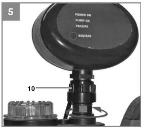
text_image
5 POWER ON PUMP ON FAILURE RESTART 10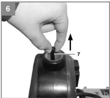
natural_image
Close-up of a hand adjusting a mechanical component with a numbered arrow and dimension label (7), no readable text or symbols present.-3-
Pattfield®
ERGO TOOLS
-4-
Pattfield® ERGO TOOLS
Inhaltsverzeichnis
Pattfield® ERGO TOOLS
Gefahr!
Pattfield® ERGO TOOLS
Pattfield® ERGO TOOLS
Pattfield® ERGO TOOLS
Pattfield® ERGO TOOLS
Pattfield® ERGO TOOLS
Pattfield® ERGO TOOLS
Pattfield® ERGO TOOLS
Pattfield® ERGO TOOLS
Pattfield® ERGO TOOLS
Pattfield® ERGO TOOLS
Pattfield® ERGO TOOLS

Nur für EU-Länder
Pattfield® ERGO TOOLS
Pattfield® ERGO TOOLS
Sommaire
Pattfield® ERGO TOOLS
Danger!
Pattfield® ERGO TOOLS
Pattfield® ERGO TOOLS
Pattfield® ERGO TOOLS
Pattfield® ERGO TOOLS
Pattfield® ERGO TOOLS
Pattfield® ERGO TOOLS
Pattfield® ERGO TOOLS
Pattfield® ERGO TOOLS
6. Commande
Pattfield® ERGO TOOLS
Pattfield® ERGO TOOLS
Pattfield® ERGO TOOLS
Pattfield® ERGO TOOLS

Pattfield® ERGO TOOLS
12. Bon de garantie
Chère cliente, cher client,
Pattfield® ERGO TOOLS
Pattfield® ERGO TOOLS
Indice
Pattfield® ERGO TOOLS
Pericolo!
Pattfield® ERGO TOOLS
Pattfield® ERGO TOOLS
Pattfield® ERGO TOOLS
Pattfield® ERGO TOOLS
Pattfield® ERGO TOOLS
Pattfield® ERGO TOOLS
Pattfield® ERGO TOOLS
Pattfield® ERGO TOOLS
Pattfield® ERGO TOOLS
Pattfield® ERGO TOOLS
Pattfield® ERGO TOOLS

Pattfield® ERGO TOOLS
Pattfield® ERGO TOOLS
Inhoudsopgave
Pattfield® ERGO TOOLS
Gevaar!
Pattfield® ERGO TOOLS
Pattfield® ERGO TOOLS
Pattfield® ERGO TOOLS
Pattfield® ERGO TOOLS
Pattfield® ERGO TOOLS
Pattfield® ERGO TOOLS
Pattfield® ERGO TOOLS
Pattfield® ERGO TOOLS
Pattfield® ERGO TOOLS
Groen brandt, rood knippert:
Pattfield® ERGO TOOLS
Pattfield® ERGO TOOLS

Pattfield® ERGO TOOLS
Pattfield® ERGO TOOLS
Pattfield® ERGO TOOLS
Fara!
Pattfield® ERGO TOOLS
Pattfield® ERGO TOOLS
Pattfield® ERGO TOOLS
Pattfield® ERGO TOOLS
Pattfield® ERGO TOOLS
Pattfield® ERGO TOOLS
Pattfield® ERGO TOOLS
Pattfield® ERGO TOOLS
Pattfield® ERGO TOOLS
Pattfield® ERGO TOOLS
Pattfield® ERGO TOOLS

Pattfield® ERGO TOOLS
Pattfield® ERGO TOOLS
Obsah
Pattfield® ERGO TOOLS
Nebezpečí!
Pattfield® ERGO TOOLS
Pattfield® ERGO TOOLS
Pattfield® ERGO TOOLS
Pattfield® ERGO TOOLS
Pattfield® ERGO TOOLS
4. Technická data
Zahradní čerpadlo
Pattfield® ERGO TOOLS
Pattfield® ERGO TOOLS
Pattfield® ERGO TOOLS
Pattfield® ERGO TOOLS
Pattfield® ERGO TOOLS
9. Likvidace a recyklace
Pattfield® ERGO TOOLS

Jen pro země EU
Pattfield® ERGO TOOLS
12.Záruční list
Pattfield® ERGO TOOLS
Pattfield® ERGO TOOLS
Obsah
Pattfield® ERGO TOOLS
Nebezpečenstvo!
Pattfield® ERGO TOOLS
Pattfield® ERGO TOOLS
Pattfield® ERGO TOOLS
Pattfield® ERGO TOOLS
Pattfield® ERGO TOOLS
4. Technické údaje
Záhradné čerpadlo
Sietové pripojenie: 230 V \~ 50 Hz
Príkon: 650 wattov
Pattfield® ERGO TOOLS
Pattfield® ERGO TOOLS
5.2 Pripojenie pre nasávacie vedenie
Pattfield® ERGO TOOLS
Pattfield® ERGO TOOLS
Pattfield® ERGO TOOLS
Pattfield® ERGO TOOLS
Pattfield® ERGO TOOLS

Len pre krajiny EÚ
Pattfield® ERGO TOOLS
12.Záručný list
Pattfield® ERGO TOOLS
Pattfield® ERGO TOOLS
Cuprins
Pattfield® ERGO TOOLS
Pericol!
Pattfield® ERGO TOOLS
Pattfield® ERGO TOOLS
Pattfield® ERGO TOOLS
Pattfield® ERGO TOOLS
Pattfield® ERGO TOOLS
Pattfield® ERGO TOOLS
Pattfield® ERGO TOOLS
Pattfield® ERGO TOOLS
Pattfield® ERGO TOOLS
Pattfield® ERGO TOOLS
8.2 Comanda pieselor de schimb:
Pattfield® ERGO TOOLS

Pattfield® ERGO TOOLS
Pattfield® ERGO TOOLS
Table of contents
- Safety regulations
- Layout and items supplied
- Proper use
- Technical data
- Before starting the equipment
- Operation
- Replacing the power cable
- Cleaning, maintenance and ordering of spare parts
- Disposal and recycling
- Storage
- Troubleshooting guide
- Warranty certifi cate
GB
Pattfield®
ERGO TOOLS

Danger! - Read the operating instructions to reduce the risk of inqui
Pattfield® ERGO TOOLS
Danger!
When using the equipment, a few safety precautions must be observed to avoid injuries and damage. Please read the complete operating instructions and safety regulations with due care. Keep this manual in a safe place, so that the information is available at all times. If you give the equipment to any other person, hand over these operating instructions and safety regulations as well. We cannot accept any liability for damage or accidents which arise due to a failure to follow these instructions and the safety instructions.
1. Safety regulations
Danger!
Read all safety regulations and instructions.
Any errors made in following the safety regulations and instructions may result in an electric shock, fire and/or serious injury. Keep all safety regulations and instructions in a safe place for future use.
Danger!
The equipment must be powered via a residual current device (RCD) with a rated fault current of no more than 30 mA (according to VDE 0100 Part 702 and 738).
If you are uncertain whether there is an RCD in your electrical installation system, we recommend using a PRCD-S safety switch (ask a qualifi ed electrician).
The equipment is not designed for use in swimming pools and paddling pools of any kind or other bodies of water in which people or animals may be present during operation. It is prohibited to operate the equipment if a person or animal is in the danger area. Ask your electrician!
Pattfield® ERGO TOOLS
This equipment can be used by children of 8 years and older and by people with limited physical, sensory or mental capacities or those with no experience and knowledge if they are supervised or have received instruction in how to use the equipment safely and understand the dangers which result from such use. Children are not allowed to play with the equipment. Unless supervised, children are not allowed to clean the equipment and carry out user-level maintenance work.
- The equipment is not allowed to be used when there are people in the water.
- The equipment is allowed to be used only with an earth-leakage circuit breaker (RCD) with a rated fault current of no more than 30 mA.
- Always inspect the equipment visually before using it. Do not use the equipment if safety devices are damaged or worn. Never disable safety devices.
- Use the equipment only for the purposes indicated in these operating instructions.
• You are responsible for safety in the work area.
- If the power cable for this equipment is damaged, it must be replaced by the manufacturer or its after-sales service or similarly trained personnel to avoid danger.
- The voltage of 230 V alternating voltage specified on the rating plate must be the same as the mains voltage.
- Never use the power cable to lift, transport or secure the equipment.
- Ensure that the electrical plug connections are in areas that are not at risk of flooding or protect them from moisture.
• Pull the mains plug before starting any work on the equipment.
- Do not expose the equipment to a direct jet of water.
- The operator is responsible for complying with local safety and installation regulations. (Ask an electrician if you are in any doubt.)
Pattfield® ERGO TOOLS
- Consequential damage caused by flooded rooms in the event of the equipment suffering faults must be prevented by the user by means of suitable measures (for example installing alarm systems or a reserve pump, etc.).
- In the event of a failure, repair work may only be carried out by an electrician or by after sales service personnel.
- The equipment must never run dry or be used when the intake line is closed fully. The manufacturer's warranty does not cover damage caused to the equipment as a result of running it dry.
- The pump must not be used to operate swimming pools.
- The equipment must not be installed in the drinking water pipe line.
- Take suitable measures to keep the equipment out of the reach of children.
- The operator is responsible for the safety of other people in the work area.
- Before starting, arrange for a specialist check whether the required electrical safety measures are in place.
GB
Pattfield® ERGO TOOLS
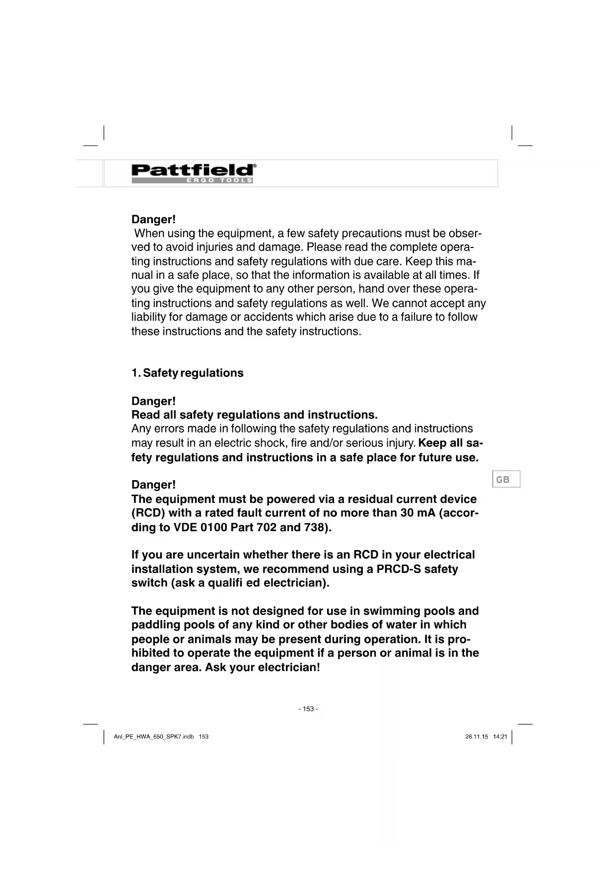
2. Layout and items supplied
2.1 Layout (Fig. 1)
- Pressure connector (R1 female thread)
- Flow switch
- Carry handle
- Power switch
- Water drain screw
- Suction connector (R1 female thread)
- Water filler screw
2.2 Items supplied
Please check that the article is complete as specified in the scope of delivery. If parts are missing, please contact our service center or the sales outlet where you made your purchase at the latest within 5 working days after purchasing the product and upon presentation of a valid bill of purchase. Also, refer to the warranty table in the service information at the end of the operating instructions.
- Open the packaging and take out the equipment with care.
- Remove the packaging material and any packaging and/or transportation braces (if available).
- Check to see if all items are supplied.
- Inspect the equipment and accessories for transport damage.
- If possible, please keep the packaging until the end of the guarantee period.
Danger!
The equipment and packaging material are not toys. Do not let children play with plastic bags, foils or small parts. There is a danger of swallowing or suff ocating!
- Garden pump
- Flow switch
• Original operating instructions
Pattfield® ERGO TOOLS
3. Proper use
Applications
- Irrigation and watering of green areas, vegetable beds and gardens.
• Operation of lawn sprinklers. - For drawing water from ponds, streams, rainwater butts, rainwater cisterns and springs
• For supplying service water
Transport media:
- For the pumping of clear water (fresh water), rainwater or light suds/service water.
- The maximum temperature of the fluid must not exceed +35°C if the equipment is operated permanently.
- Do not use the equipment to pump inflammable, gassing or explosive fluids.
- The pumping of aggressive liquids (acids, alkalis, silo seepage etc.) as well as liquids with abrasive substances (sand) must likewise be avoided.
• This equipment is not designed to convey drinking water.
The equipment is to be used only for its prescribed purpose. Any other use is deemed to be a case of misuse. The user / operator and not the manufacturer will be liable for any damage or injuries of any kind caused as a result of this.
Please note that our equipment has not been designed for use in commercial, trade or industrial applications. Our warranty will be voided if the machine is used in commercial, trade or industrial businesses or for equivalent purposes.
GB
Pattfield® ERGO TOOLS
4. Technical data
Garden pump
Mains connection: 230 V \~ 50 Hz
Power consumption: 650 W
Pumping rate max. 3600 l/h
Delivery head max. 36 m
Delivery pressure max. 0.36 MPa (3.6 bar)
Suction height max. 8 m
Pressure connection: ....approx. 33.3 mm (R1 female thread)
Suction connection: ....approx. 33.3 mm (R1 female thread)
Water temperature max. 35°C
L_WA sound power level guaranteed: 85 dB(A)
Protection type: IPX4
Flow switch
Mains voltage: 230 V\~ / 50 Hz
Max. current strength: 10 A
Protection type: IP 44
Max. operating pressure: 1.0 MPa (10 bar)
Max. temperature: 55°C
5. Before starting the equipment
Before you connect the equipment to the mains supply make sure that the data on the rating plate are identical to the mains data.
As a basic principle, we recommend the use of a preliminary filter and a suction set with suction hose, intake cage and non-return valve, in order to prevent long priming periods and unnecessary damage to the pump as a result of stones and solid foreign bodies.
Pattfield® ERGO TOOLS
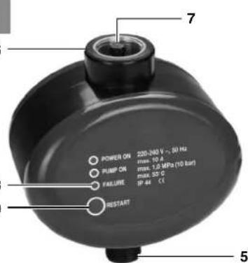
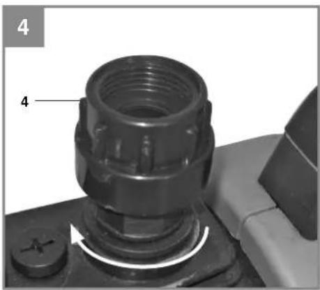
5.1 Installation and start-up
Switchoff the pump and pull the pump's mains plug. Remove the existing output line on the actual pump. Ensure that you bleed the pump correctly (refer to the pump's manual for further details). Screw the connection adapter (Fig. 1 / Item 4) to the output line connector on the pump (Fig 3). Fit the flow switch (Fig. 1 / Item 1) with the connection thread (Fig. 2 / Item 5) to the connection adapter and secure it to the connection adapter using the union nut (Fig. 4 / Item 10) (Fig. 4). The flow switch must be in an upright position, in other words the connector for the pump (Fig. 2 / Item 5) must be at the bottom and the connector for the output line (Fig. 2 / Item 6) must be at the top. If it is in any other position, the flow switch cannot work correctly. Raise the non-return valve at the handle (Fig. 2 / Item 7) (Fig. 5) and carefully fill the flow switch with the transport fluid up to the bottom end of the thread on the pressure connector (Fig. 2 / Item 6) to prevent the system running dry. Now screw the output line to the connector provided for it (Fig. 2 / Item 6) on the flow switch and ensure that you seal the connection properly, for example with Teflon tape (not supplied). Connect the pump's mains plug to the socket (Fig. 1 / Item 2) on the rear of the flow switch. After checking all the connections and lines, connect a consumer to the output line and open it so that any air in the output line can escape when the transport process is started. Connect the mains lead (Fig. 1 / Item 3) on the flow switch to an adequately fused (at least 10 A) 230V 50Hz safety mains socket with a ground contact. The flow switch is now ready for use. Switch on the pump if it is fitted with a switch, otherwise the pump will now start automatically and will start to transport the medium. The consumer can be closed as soon as the transport fluid is emitted from it. The flow switch will now switch off the socket (Fig. 1 / Item 2). To dismantle, proceed in reverse order. If you place it into storage, ensure that the flow switch does not contain any transport fluid so as to avoid frost damage.
GB
Pattfield® ERGO TOOLS
5.2 Connecting the intake line
- Fasten the suction hose (at least approx. 19 mm ( ^3/4 ") plastic hose with spiral reinforcement) to the suction connection (5) approx. 33.3 mm (R1 female thread) of the equipment either directly or via a threaded nipple.
- The suction hose used should be equipped with an intake valve. If the intake valve cannot be used, a non-return valve should be installed in the intake line.
- Position the intake line so that it rises from the water withdrawal point to the equipment. Avoid positioning the intake line higher than the pump, as this would delay the escape of air bubbles from the intake line and impede the priming process.
- Install the intake and discharge lines in such a way that they do not exert any mechanical pressure on the equipment.
- The intake valve should be low enough in the water to ensure that if the water level falls, the unit will not run dry.
- A leaking intake line will draw in air and therefore not draw in any water.
- Prevent the intake of foreign bodies (sand, etc.). If necessary, install a coarse filter for this purpose.
5.3 Connecting the discharge line
- The discharge line (min. 19 mm ( ^3/4 ")) must be connected to the 33.3 mm (R1IG) female thread discharge line connector (1) of the equipment either directly or with the aid of a threaded nipple.
- With the right couplings it is also possible, of course, to use a 13 mm ( 12 " ) delivery hose. The smaller delivery hose results in a lower delivery rate.
- During the priming operation, fully open any shut-off mechanisms (spray nozzles, valves, etc.) in the pressure line so that the air can escape without obstruction.
Pattfield® ERGO TOOLS
5.4 Electrical connections
- Connect the appliance to a 230 V \~ 50 Hz socket-outlet with earthing contact. Minimum fuse 10 ampere.
- A built-in thermostat protects the motor from overloading and blocking. The pump is switched off automatically by the thermostat if overheating occurs and is switched on again automatically after cooling.
6. Operation
• Install the equipment on a solid and level surface.
- Fill the pump housing with water via the water filler screw (7). Filling the intake line will accelerate the priming process.
- All the shut-off devices in the discharge line (spray nozzle, valves etc.) must be fully opened during intake in order to permit all air to escape from the intake line.
- Connect the mains cable.
- Switch on the equipment with the power switch (4) - water can be suctioned in for up to 5 minutes (maximum suction height).
- After finishing the work, switch off the equipment with the power switch (4).
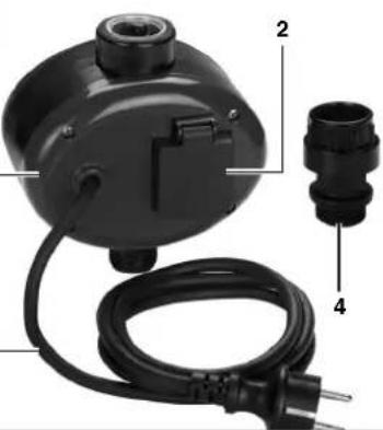
The flow switch cannot be adjusted or switched, it is fully automatic. There are only 3 LEDs (Fig. 3 / Item 8) to indicate its operating status.
Green LED:
The flow switch is connected to the power supply
Yellow LED:
The flow switch has tripped, the socket (Fig. 2 / Item 2) is live.
Red LED:
The flow switch has detected a fault
Pattfield® ERGO TOOLS
The following operating statuses are indicated:
Green is lit:
The flow switch is ready for use, no transport fluid is required. The pump is not running.
Green and yellow are lit:
The pump is operating, a consumer for discharging transport fluid is open.
Green and red are lit:
The pump is running dry without transport fluid. The flow switch will attempt to rectify the dry running three times before the dry running guard fi nally trips.
Green is lit, red is fl ashing:
The dry running guard has tripped, it is no longer possible to draw in the transport fluid. Find the cause of the fault using the pump's operating manual (for example leaking intake line) and rectify it. Then restart the pump by pressing the Reset button (Fig. 3 / Item 9) on the flow switch.
7. Replacing the power cable
Danger!
If the power cable for this equipment is damaged, it must be replaced by the manufacturer or its after-sales service or similarly trained personnel to avoid danger.
GB
Pattfield® ERGO TOOLS
8. Cleaning, maintenance and ordering of spare parts
The equipment is almost completely maintenance free. In order to ensure a long service life, however, we recommend that you regularly check and care for the product.
Danger!
The equipment must be disconnected from the power supply (pull the power plug) prior to performing any maintenance.
8.1 Servicing
- If the equipment becomes clogged, connect the discharge line to the water line and disconnect the suction hose. Open the water line. Switch on the equipment several times for approx. two seconds. This should resolve the majority of clog-related problems.
- There are no parts inside the equipment which require additional maintenance.
8.2 Ordering replacement parts:
Please quote the following data when ordering replacement parts:
- Type of machine
• Article number of the machine
• Identification number of the machine
• Replacement part number of the part required
Current prices and information are available on request at your Hornbach store.
GB
Pattfield® ERGO TOOLS
9. Disposal and recycling
The equipment is supplied in packaging to prevent it from being damaged in transit. The raw materials in this packaging can be reused or recycled. The equipment and its accessories are made of various types of material, such as metal and plastic. Never place defective equipment in your household refuse. The equipment should be taken to a suitable collection center for proper disposal. If you do not know the whereabouts of such a collection point, you should ask in your local council offices.
10.Storage
Store the equipment and accessories in a dark and dry place at above freezing temperature. The ideal storage temperature is between 5 and 30 °C. Store the electric tool in its original packaging.
- If the pump is not going to be used for a long time or has to be removed for the winter months, rinse it out with water, empty it completely and allow it to dry.
- The equipment must be completely drained before it is subjected to frost.
- After long stoppages, make sure the rotor turns correctly by briefly switching the pump on and off.
GB
- Troubleshooting guide
| Faults Cause Remedy | ||
| Motor fails to start up | -Nomainsvoltage- Pump rotor blocked -thermostat switched off | -Checkvoltage- Dismantle and clean pump |
| No intake - | Intake valve not in water- Pump chamber without water connection- Air in intake line air-tight- Intake valve leaks- Strainer (intake valve) blocked- Max. suction height exceeded | -Immerseintakevalvein water- Fill water into intake- Make sure intake line is close- Clean intake valve- Clean strainer- Check suction height |
| Inadequate delivery rate | - Suction height too high- Strainer dirty- Water level falling rapidly- Pump performance diminished by contaminants part | -Checksuctionheight- Clean strainer- Place the suction hose at a deeper level- Clean pump and replace wearing |
| Thermostat switches pump off | - Motor overloaded - friction caused by foreign substances too high | -Dismantleandclean pump. Prevent intake of foreign substances (fi l-ter) |
GB
Pattfield® ERGO TOOLS

For EU countries only
Never place any electric power tools in your household refuse.
To comply with European Directive 2012/19/EC concerning old electric and electronic equipment and its implementation in national laws, old electric power tools have to be separated from other waste and disposed of in an environment-friendly fashion, e.g. by taking to a recycling depot.
Recycling alternative to the return request:
As an alternative to returning the equipment to the manufacturer, the owner of the electrical equipment must make sure that the equipment is properly disposed of if he no longer wants to keep the equipment.
The old equipment can be returned to a suitable collection point that will dispose of the equipment in accordance with the national recycling and waste disposal regulations. This does not apply to any accessories or aids without electrical components supplied with the old equipment.
GB
The reprinting or reproduction by any other means, in whole or in part, of documentation and papers accompanying the products is permitted only with the express consent of Hornbach Baumarkt AG.
Subject to technical changes
12.Warranty certifi cate
Dear Customer,
All of our products undergo strict quality checks to ensure that they reach you in perfect condition. In the unlikely event that your device develops a fault, please contact our service department at the address shown on this guarantee card or the sales outlet from where you bought the device. Please note the following terms under which guarantee claims can be made:
-
These warranty terms regulate additional warranty services, which the manufacturer mentioned below promises to buyers of its new products in addition to their statutory rights of guarantee. Your statutory guarantee claims are not affected by this guarantee. Our guarantee is free of charge to you.
-
The warranty services cover only defects due to material or manufacturing faults on a product which you have bought from the manufacturer mentioned below and are limited to either the rectification of said defects on the product or the replacement of the product, whichever we prefer.
Please note that our devices are not designed for use in commercial, trade or professional applications. A guarantee contract will not be created if the device has been used by commercial, trade or industrial business or has been exposed to similar stresses during the guarantee period.
- The following are not covered by our guarantee:
- Damage to the device caused by a failure to follow the assembly instructions or due to incorrect installation, a failure to follow the operating instructions (for example connecting it to an incorrect mains voltage or current type) or a failure to follow the maintenance and safety instructions or by exposing the device to abnormal environmental conditions or by lack of care and maintenance. - Damage to the device caused by abuse or incorrect use (for example overloading the device or the use or unapproved tools or accessories), ingress of foreign bodies into the device (such as
GB
Pattfield® ERGO TOOLS
sand, stones or dust, transport damage), the use of force or damage caused by external forces (for example by dropping it).
- Damage to the device or parts of the device caused by normal or natural wear or tear or by normal use of the device.
- The guarantee is valid for a period of 3 years starting from the purchase date of the device. Guarantee claims should be submitted before the end of the guarantee period within two weeks of the defect being noticed. No guarantee claims will be accepted after the end of the guarantee period. The original guarantee period remains applicable to the device even if repairs are carried out or parts are replaced. In such cases, the work performed or parts fitted will not result in an extension of the guarantee period, and no new guarantee will become active for the work performed or parts fitted. This also applies if an on-site service is used.
Also refer to the restrictions of this warranty concerning wear parts, consumables and missing parts as set out in the service information in these operating instructions.
GB
Hornbach Baumarkt AG, Hornbachstraße 11, 76879 Bornheim / Germany www.hornbach.com
Pattfield®
ERGO TOOLS

Pattfield® ERGO TOOLS
Manufactured for HORNBACH-Baumarkt AG
Hornbachstraße 11, 76879 Bornheim / Germany
ED201507