CL 200 G2 - Lamp Cameo - Free user manual and instructions
Find the device manual for free CL 200 G2 Cameo in PDF.
Download the instructions for your Lamp in PDF format for free! Find your manual CL 200 G2 - Cameo and take your electronic device back in hand. On this page are published all the documents necessary for the use of your device. CL 200 G2 by Cameo.
USER MANUAL CL 200 G2 Cameo
SET-UP AND INSTALLATION 8
MANUFACTURER’S DECLARATIONS 11
DMX ENGLISH YOU‘VE MADE THE RIGHT CHOICE! We have designed this product to operate reliably over many years. Please read this User‘s Manual carefully, so that you can begin making optimum use of your Cameo Light product quickly. Learn more about Cameo Light on our website WWW.CAMEOLIGHT.COM. PREVENTIVE MEASURES
1. Please read these instructions carefully.
2. Keep all information and instructions in a safe place.
3. Follow the instructions.
4. Observe all safety warnings. Never remove safety warnings or other information from the equipment.
5. Use the equipment only in the intended manner and for the intended purpose.
6. Use only sufficiently stable and compatible stands and/or mounts (for fixed installations). Make certain that wall mounts are properly installed and secured. Make certain that the equipment is installed securely and cannot fall down.
7. During installation, observ e the applicable safety regulations for your country.
8. Never install and operate the equipment near radiators, heat registers, ovens or other sources of heat. Make certain that the equipment is always installed so that is cooled sufficiently and cannot overheat.
9. Never place sources of ignition, e.g., burning candles, on the equipment.
10. Ventilation slits must not be blocked.
11. Keep a minimum distance of 20 cm around and above the device.
12. Do not use this equipment in the immediate vicinity of water (does not apply to special outdoor equipment - in this case, observe the special instructions noted below. Do not expose this equipment to flammable materials, fluids or gases. Avoid direct sunlight! 13. Make certain that dripping or splashed water cannot enter the equipment. Do not place containers filled with liquids, such as vases or drinking vessels, on the equipment.
14. Make certain that objects cannot fall into the device.
15. Use this equipment only with the accessories recommended and intended by the manufacturer.
16. Do not open or modify this equipment.
17. After connecting the equipment, check all cables in order to prevent damage or accidents, e.g., due to tripping hazards. 18. During transport, make certain that the equipment cannot fall down and possibly cause property damage and personal injuries. 19. If your equipment is no longer functioning properly, if fluids or objects have gotten inside the equipment or if it has been damaged in anot her way, switch it off immediately and unplug it from the mains outlet (if it is a powered device). This equipment may only be repaired by authorized, qualified personnel.
20. Clean the equipment using a dry cloth.
21. Comply with all applicable disposal laws in your country. During disposal of packaging, please separate plastic and paper/cardboard.
22. Plastic bags must be kept out of reach of children.
23. Please note that changes or modifications not expressly approved by the party responsible for compliance could void the user´s authority to operate the equipment. FOR EQUIPMENT THAT CONNECTS TO THE POWER MAINS: 24. CAUTION: If the power cord of the device is equipped with an earthing contact, then it must be connected to an outlet with a protective ground. Never deactivate the protective ground of a power cord. 25. If the equipment has been exposed to strong fluctuations in temperature (for example, after transport), do not switch it on immediately. Moisture and condensation could damage the equipment. Do not switch on the equipment until it has reached room temperature. 26. Before connecting the equipment to the power outlet, first verify that the mains voltage and frequency match the values specified on the equipment. If the equipment has a voltage selection switch, connect the equipment to the power outlet only if the equipment values and the mains power values match. If the included power cord or power adapter does not fit in your wall outlet, contact your electrician. 27. Do not step on the power cord. Make certain that the power cable does not become kinked, especially at the mains outlet and/or power adapter and the equipment connector. 28. When connecting the equipment, make certain that the power cord or power adapter is always freely accessible. Always disconnect the equipment from the power supply if the equipment is not in use or if you want to clean the equipment. Always unplug the power cord and power adapter from the power outlet at the plug or adapter and not by pulling on the cord. Never touch the power cord and power adapter with wet hands. 29. Whenever possible, avoid switching the equipment on and off in quick succession because otherwise this can shorten the useful life of the equipment. 30. IMPORTANT INFORMATION: Replace fuses only with fuses of the same type and rating. If a fuse blows repeatedly, please contact an authorised service centre. 31. To disconnect the equipment from the power mains completely, unplug the power cord or power adapter from the power outlet. 32. If your device is equipped with a Volex power connector, the mating Volex equipment connector must be unlocked before it can be re- moved. However, this also means that the equipment can slide and fall down if the power cable is pulled, which can lead to personal injuries and/or other damage. For this reason, always be careful when laying cables. 33. Unplug the power cord and power adapter from the power outlet if there is a risk of a lightning strike or before extended periods of disuse.
34. The device must only be installed in a voltage-free condition (disconnect the mains plug from the mains).
35. Dust and other debris inside the unit may cause damage. The unit should be regularly serviced or cleaned (no guarantee) depending on ambient conditions (dust etc., nicotine, fog) by qualified personnel to prevent overheating and malfunction.
36. Please keep a distance of at least 0.5 m to any combustible materials.
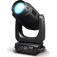
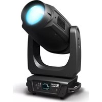
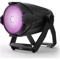
37. Power cables to power multiple devices must have a cross-section of at least 1.5 mm². Within the EU, the cables must correspond to H05VV-F, or similar. Suitable cables are offered by Adam Hall. With these cables, you can connect multiple devices via the power OUT connection4 DEUTSCHFRANCAIS ESPAÑOL ENGLISH ITALIANO POLSKIDMX to the power IN connection of an additional device. Make sure that the total current consumption of all connected devices does not exceed the specified value on all connected devices (label on the device). Make sure to keep power cable connections as short as possible. CAUTION: To reduce the risk of electric shock, do not remove cover (or back). There are no user serviceable parts inside. Maintenance and repairs should be exclusively carried out by qualified service personnel. The warning triangle with lightning symbol indicates dangerous uninsulated voltage inside the unit, which may cause an electrical shock. The warning triangle with exclamation mark indicates important operating and maintenance instructions. Warning! This symbol indicates a hot surface. Certain parts of the housing can become hot during operation. After use, wait for a cool-down period of at least 10 minutes before handling or transporting the device. Warning! This device is designed for use below 2000 metres in altitude. Warning! This product is not intended for use in tropical climates. Caution! Powerful light emission. Danger to Eyesight. Do not stare at the light source CAUTION! HIGH VOLUMES IN AUDIO PRODUCTS! This device is meant for professional use. Therefore, commercial use of this equipment is subject to the respectively applicable national accident prevention rules and regulations. As a manufacturer, Adam Hall is obligated to notify you formally about the existence of potential health risks. Hearing damage due to high volume and prolonged exposure: When in use, this product is capable of producing high sound-pressure levels (SPL) that can lead to irreversible hearing damage in performers, employees, and audience members. For this reason, avoid prolonged exposure to volumes in excess of 90 dB. INTRODUCTION LED SPOTLIGHT CLCL200G2 CONTROL FUNCTIONS: 1-channel, 2-channel 1, 2-channel 2, 3-channel, 4-channel DMX control Master/slave mode Standalone functions FEATURES: DMX-512 control. 200 W high-intensity cold white/warm white COB LED. Stroboscope. 4 dimmer curves. Color temperature settings from 7800 K to 3200 K. 3-pin DMX connections. Stand or mounting bracket. Flap included. Operating voltage 100–240 V AC. Power consumption 200 W.ITALIANO POLSKI ESPAÑOL FRANCAIS DEUTSCH ENGLISH
POWER IN Blue power input socket for power supply to the device. A suitable power cable is included.
POWER OUT White power output socket for the power supply of additional CAMEO spotlights. Ensure that the total current consumption of all connected devices does not exceed the value specified on the device in amperes (A).
FUSE Fuse holder. Fuse F3AL/250 V (5 x 20 mm). IMPORTANT: Replace the fuse only with a fuse of the same type and value. In the event of repeated fuse failure, please contact an authorised service centre.
DMX IN Male 3-pin XLR socket for connection to a DMX control device (e.g. DMX console).
DMX OUT Female 3-pin XLR socket for sending the DMX control signal.
LC DISPLAY The illuminated LC display shows the operating mode and other system information.
OPERATING KEYS MODE – press MODE to access the selection menu for system settings. Press repeatedly to return to the main display. ENTER – press ENTER to access the menu levels so as to be able to change settings and access the sub-menus. Confirm changed settings by pressing ENTER. UP and DOWN – select individual menu items in the selection menu (DMX address, operating mode etc.) and in the sub-menus. Allow changes to be made to a menu item setting such as the DMX address as required.
Overhead installation may only be carried out by qualified personnel. A suitable safety cable must be fitted to the spotlight’s securing lug to ensure that it does not fall down.6 DEUTSCHFRANCAIS ESPAÑOL ENGLISH ITALIANO POLSKIDMX
OPERATION As soon as the spotlight is correctly connected to the power supply, the following will be displayed in succession: "Welcome to Cameo", the model name and the software version. After this process, the spotlight is ready for operation and starts in the previously selected mode. If the DMX operating mode is activated and there is no DMX signal at the DMX input, the display will start to flash after a few seconds. After approxi- mately 1 minute of inactivity, the display will automatically show the currently active operating mode. SET DMX START ADDRESS (DMX Addr) Press the MODE button repeatedly until "Menu" appears in the top line of the display. If necessary, select the menu item "Menu DMX Addr" using UP and DOWN and press ENTER. Now select the desired DMX start address using UP and DOWN, and press ENTER to confirm. Menu DMX Addr DMX Addr 001–512 ENTER UP/DOWN ENTER SET OPERATING MODE (Mode) Press the MODE button repeatedly until "Menu" appears in the top line of the display. If necessary, select the menu item "Menu Mode" us- ing UP and DOWN and then press ENTER. Now select the desired operating mode using UP and DOWN and confirm with ENTER (see tables, note sub-menus). The comprehensive DMX tables can be found in these instructions under “DMX CONTROL”. Operating Modes Mode DMX = DMX operating mode 1CH 2CH_1 2CH_2 3CH 4CH = 5 different DMX modes to choose from. DMX tables – see "DMX CONTROL". Mode Slave = slave mode Slave = connect DMX IN on the slave unit to DMX OUT on the master unit (same model) and enable the standalone mode "Static" on the master unit. The slave unit will now follow the master unit. Mode Static = set a "scene" without an external controller. Static = dimmer, stroboscope (approx. 1–30 Hz), cold white and warm white can be adjusted individually to settings between 000 and 255.ITALIANO POLSKI ESPAÑOL FRANCAIS DEUTSCH ENGLISH
SYSTEM INFORMATION (System) In order to view system information, press the MODE button repeatedly until "Menu" appears in the top line of the display. If necessary, select the menu item "Menu System" using UP and DOWN and press ENTER. Use UP and DOWN to select the desired sub-menu item, and press ENTER to display the relevant information. RESET To restore the spotlight's factory settings, keep the MODE button pressed down for approx. 5 seconds.
SET-UP AND INSTALLATION
The integrated double bracket allows the lamp to be positioned in a suitable location on a level surface. Installation on a traverse is possible using a suitable traverse clamp (not supplied). Ensure firm connection to the mounting bracket and secure the spotlight to the securing lug (A) with a suitable safety cable. Important: Overhead installation may only be carried out by qualified personnel. AITALIANO POLSKI ESPAÑOL FRANCAIS DEUTSCH ENGLISH
DMX FLAP In order to mount the flap included, remove the four screws from the lens attachment frame (see arrows in the figure below), place the flap on the frame and screw it into place using the screws previously removed. The flap can also be attached on the spotlight at a 90° rotation. DMX TECHNOLOGY DMX-512 DMX (Digital Multiplex) is the designation for a universal transmission protocol for communications between corresponding devices and controllers. A DMX controller sends DMX data to the connected DMX device(s). The DMX data is always transmitted as a serial data stream that is forwarded from one connected device to the next via the "DMX IN" and "DMX OUT" connectors (XLR plug-type connectors) that are found on every DMX-capable device, provided the maximum number of devices does not exceed 32 units. The last device in the chain needs to be equipped with a terminator (terminating resistor). DMX CONNECTION DMX is the common "language" via which a very wide range of types and models of equipment from various manufacturers can be connected with one another and controlled via a central controller, provided that all of the devices and the controller are DMX compatible. For optimum data transmission, it is necessary to keep the connecting cables between the individual devices as short as possible. The order in which the devices are integrated in the DMX network has no influence on the addresses. Thus the device with the DMX address 1 can be located at any position in the (serial) DMX chain: at the beginning, at the end or somewhere in the middle. If the DMX address 1 is assigned to a device, the controller "knows" that it should send all data allocated to address 1 to this device regardless of its position in the DMX network.
SERIAL CONNECTION OF MULTIPLE LIGHTS
1. Connect the male XLR connector (3-pin or 5-pin) of the DMX cable to the DMX output (female XLR socket) of the first DMX device (e.g. DMX-Controller). 2. Connect the female 3-pin XLR connector of the DMX cable connected to the first projector to the DMX input (male 3-pin socket) of the next DMX device. In the same way, connect the DMX output of this device to the DMX input of the next device and repeat until all devices have been connected. Please note that as a rule, DMX devices are connected in series and connections cannot be shared without active splitters. The maximum number of DMX devices in a DMX chain should not exceed 32 units. The Adam Hall 3 STAR, 4 STAR, and 5 STAR product ranges include an extensive selection of suitable cables. DMX CABLES When fabricating your own cables, always observe the illustrations on this page. Never connect the shielding of the cable to the ground contact of the plug, and always make certain that the shielding does not come into contact with the housing of the XLR plug. If the shielding is connected to the ground, this can lead to short-circuiting and system malfunctions. Pin Assignment DMX cable with 3-pin XLR connectors: DMX cable with 5-pin XLR connectors (pin 4 and 5 are not used): Shield
Shield10 DEUTSCHFRANCAIS ESPAÑOL ENGLISH ITALIANO POLSKIDMX DMX TERMINATORS (TERMINATING RESISTORS) To prevent system errors, the last device in a DMX chain needs to be equipped with a terminating resistor (120 ohm, 1/4 Watt). 3-pin XLR connector with a terminating resistor: K3DMXT3 5-pin XLR connector with a terminating resistor: K3DMXT5 Pin Assignment 3-pin XLR connector: 5-pin XLR connector:
DMX ADAPTER The combination of DMX devices with 3-pin connectors and DMX devices with 5-pin connectors in a DMX chain is possible with suitable adapters. Pin Assignment DMX Adapter 5-pin XLR male to 3-pin XLR female: K3DGF0020 Pins 4 and 5 are not used. Pin Assignment DMX Adapter 3-pin XLR male to 5-pin XLR female: K3DHM0020 Pins 4 and 5 are not used. TECHNICAL DATA Model name: CLCL200G2 Product type: LED spotlight Type: Indoor LED color spectrum: Cold white–warm white No. of LEDs: 1 LED type: 200 W LED color temperature: 7800–3200 K Refresh rate: 17500 Hz Beam angle: 25° (50° field) DMX input: 3-pin male XLR DMX output: 3-pin female XLR DMX mode: 1-channel, 2-channel 1, 2-channel 2, 3-channel, 4-channel DMX functions: Dimmer, stroboscope, cold white, warm white Standalone functions: Master/slave mode, stroboscope, dimmer response, dimmer curves, static mode Stroboscope: Approx 1–30 Hz Control: USITT DMX512 Operating controls: Mode, Enter, Up, Down Display elements: Illuminated, 2-line LC display Operating voltage: 100–240 V AC / 50–60 Hz Power consumption: 200 W Light intensity (@ 1 m): 32000 lx Lighting power: 12000 lm Power connection: Blue mains input socket white power output socket (max. 6 A) Fuse: F3AL/250 V (5 x 20 mm) Ambient temperature (in operation): 0°C – 40°C Relative air humidity: <85%, non-condensing Housing material: Metal Housing color: BlackITALIANO POLSKI ESPAÑOL FRANCAIS DEUTSCH ENGLISH
DMX Housing cooling: Temperature controlled fan Dimensions (W x H x D, without mounting bracket): 170 x 170 x 380 mm Weight: 4.2 kg Additional features: Adjustable mounting bracket or stand, securing lug, power cable and flap supplied