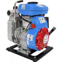
GMPS 100 - Water pump Güde - Free user manual and instructions
Find the device manual for free GMPS 100 Güde in PDF.


| Product type | Gasoline water pump motor pump |
| Brand | Güde |
| Model | GMPS 100 |
| Dimensions (L x W x H) | 360 x 310 x 380 mm |
| Weight | 13 kg |
| Fuel type | Unleaded gasoline |
| Engine type | 4-stroke, air-cooled |
| Displacement | 97.7 cm³ |
| Engine power | 1.1 kW (1.5 HP) |
| Maximum flow rate | 10,000 l/h |
| Maximum suction height | 4 m |
| Maximum discharge height | 15 m |
| Maximum water pressure | 1.5 bar |
| Connection diameter (suction/discharge) | Approx. 40 mm (1 1/2" AG) |
| Fuel tank capacity | 1.4 L |
| Recommended engine oil | 15W-40, 0.6 L |
| Maximum water temperature | +40°C |
| Sound level (LWA) | 103 dB |
| Main functions | Pumping clean or slightly dirty water, irrigation, dewatering, filling |
| Maintenance and cleaning | Annual oil change, air filter cleaning every 3 months/50h, spark plug check every 6 months/100h |
| Safety | Low oil protection (automatic shutdown) |
| Spare parts and repairability | Spark plug, air filter, seal (gasket), pump impeller |
| General information | Manufacturer warranty, CE conformity, order number 94251 |
Frequently Asked Questions - GMPS 100 Güde
User questions about GMPS 100 Güde
0 question about this device. Answer the ones you know or ask your own.
Ask a new question about this device
Download the instructions for your Water pump in PDF format for free! Find your manual GMPS 100 - Güde and take your electronic device back in hand. On this page are published all the documents necessary for the use of your device. GMPS 100 by Güde.
USER MANUAL GMPS 100 Güde
Translation of original operating instructions
MOTOR PUMP-SET
Francais F
Please read carefully these Operating Instructions before putting the appliance into operation.
| A.V.2 Any reprints, even partial, are subject to approval. Technical changes reserved. | ||
| Do you have any technical questions? A claim? Do you need spare parts or the Operating Instructions? You will be helped quickly and without needless bureaucracy at our webpage www.guide.com in the Services part. Please help us be able to assist you. To be able to identify your appliance when claimed, we need to know its serial No., order No. and year of production. All these details can be found on the type label. Enter the details below for future reference. | ||
| Serial No. | Order No. | Year of production: |
| Tel.: +49 (0) 79 04 / 700-360 | Fax: +49 (0) 79 04 / 700-51999 | E-Mail: support@ts.guide.com |
Identification:
Warnings/prohibitions:


Product safety:
| CE | |
| The product complies with relevant EU standards |
Environment protection:
| PAP | |
| Dispose waste not to harm your environment. | Packaging material from cardboard can be recycled in a collection point. |
| Defective and/or disposed electric or electronic devices must be delivered to relevant collection points. |
Technical data:
| Motor power Volume of cylinders | |
| l/h | (m) |
| Delivered volume Suction lift | |
| (m) | |
| Total head Weight | |
| Lb | |
| Noise level Pressure | connection |
Device description (figure A/B)
- Tank
- Tank lid
- Exhaust
- Frame
- Suction neck
- Rubber foot
- Oil level indicator
- Oil draining screw
- Oil low level sensor
- ON/OFF switch
- Bowden starter
- Throttle lever
- Filling neck
- Output neck
- Saturator
- Air filter
- Carburettor
- Draining screw
- Gasoline cock
Accessories (Fig. C)
- 4 m suction fitting
- 10 m outlet hose
- 1 x wrench for spark plugs
EU DECLARATION ON CONFORMITY
The company
Güde GmbH & Co. KG
Birkichstrasse 6
74549 Wolpertshausen
Germany,
hereby declares that the design and structure of the devices listed below and in designs marketed conforms to applicable basic requirements of the EU directives on safety and hygiene.
This declaration on conformity becomes void in case of a change to the device not consulted with us.
Identification of the devices:
MOTOR PUMP-SET GMPS 100
Order No.:
94251
Applicable EU directives:
2006/42EG
2004/108EG
2005/88 EG
2002/95 EG
2004/26 EG
Harmonized standards used
EN 809/AC:2010
EN 1679-1/A1:2011
Type Approval No:
e2497/68SA2002/88015200
Date/signature of manufacturer: 12.12.2011

Information about signer: managing director
Mr
Arnold
Technical documentation: J. Burkle FBL; QS
Warranty
The warranty applies exclusively on material or production defects. For warranty claims, please submit an original proof of purchase with date of purchase indicated.
The warranty does not cover unprofessional use, such as overloading, violent use, damage caused by third party or a thing. The warranty also does not cover failure to comply with the operation manual and normal wear and tear.
Technical information GMP 100
| Engine type (air cooled) | 4 Takt-Motor |
| Volume of cylinders | 97,7 ccm |
| Motor power 1,1 kW – | 1,5 PS |
| Max delivered volume | 10.000 l/h |
| Max water pressure in piping | 1,5 bar |
| Max suction lift 4 m | |
| Max total head 15 m | |
| Ø pressure/suction connector | ca. 40 mm |
| Tank volume 1,4 l | |
| Pressure connector 1,5" AG | |
| Fuel unleaded gasoline | |
| Engine oil 15W-40/0,6 l | |
| Max water temperature | + 40 °C |
| Noise level LWA 103 dB | |
| Weight | 13 kg |
| Dimensions length x width x height | 360x310x380 mm |
General safety instructions
Please read through this user guide and make sure you know all controls and proper use of this product. We shall not be responsible for damage caused by non-adherence of the instructions and procedures in this user guide. Damage due to non-adherence of the instructions and procedures are excluded from warranty. Keep the user guide well and pass it to a new owner of the machine.
Children and person not informed about content of this user guide must not operate the machine. Supervise children to prevent playing with the machine. Applicable directives in certain countries restrict minimum age of the potential user and these directives must be respected.
Physically and mentally handicapped persons or persons with sensorial limitations must not operate the machine albeit under supervision of a security engineer or based on instructions for operation received from a responsible person.
Please obey the special safety instructions listed in the chapters of this user guide.
Cautions and instructions with the following symbol must be followed with special care:

4 Failure to comply with this instruction may result in and to humans and/or material damage!
Check the machine for transport damage. In case of damage, inform your sales representative immediately.
The pump is not suitable for pumping of salt water, faecal solids, flammable, corrosive, explosive and other dangerous liquids. Furthermore, the pump is not suitable for pumping of potable water and other foods.
The transported liquid must not drop below or exceed minimum or maximum liquid temperature specified in the technical data.
Emergency procedures
For reasons of potential injury, a first aid box according to DIN 13164 must be available on workplace. Replenish immediately material used from the first aid box.
If you require assistance, please give the following details:
Place of accident Type of accident Number of injured persons Type of injury
Administer first aid according to injury and call for qualified medical assistance.
Protect injured person against other injuries and keep him/her in rest.
Application according to intended use
Gasoline engine pump for pumping of clean or moderately contaminated water. Any other use contradicts to the intended use. Manufacturer is not responsible for subsequent damage and injuries. Please note the appliance is intended for domestic use only.
Area of applicability
The machine is suitable for pumping of clean or moderately contaminated water.
Thanks to high performance, the model can be used industrially and in agriculture.
Standard areas of applicability of the gasoline engine pump:
water delivery on construction sites
irrigation of gardens, flowerbeds, fields and raining
- pumping of water from wells, tanks, flows, streams etc.
draining and filling of fish ponds, pits etc.
Disposal
Disposal instructions are illustrated in the form of pictograms on the device or packaging. Description of the pictograms is given in "Identification" chapter.
Disposal of transport packaging
Packaging protects the device against damage during transport. Packaging materials are usually selected according to their effect on environment and disposal methods and can therefore be recycled. Returning of the packaging back to circulation saves resources and costs for packaging disposal. Parts of the packaging (e.g. foil, styropor) may be dangerous for children. Risk of suffocation! Keep these parts of the packaging out of reach of children and dispose as soon as possible.
Operator requirements
The operators must thoroughly read operation manual before use.
Qualification
Except for thorough training by an expert for use of the device, no special qualification is required.
Minimum age
The machine may be used by persons over 18 years and trained in handling and function of the machine. Supervision is required for persons from 16 to 18 years.
An exception is use by younger person if the use takes place under supervision of an adult trainer in the course of education.
Training
Use of the device requires corresponding guidance by an expert or operation manual only. No special training is required.
Transport and storing
- For long-term storing, the machine must be thoroughly cleaned and no unauthorized persons may have access to the machine.
- Secure the machine against turning over before each transport.
Assembly/first commissioning
The gasoline engine pump is installed in a stable cage made from steel tubes with vibration damper. These devices must not be disassembled during operation because they provide stability and reduce vibrations.
General installation instructions

All connection piping must be absolutely tight. Leaking may influence operation of the pump negatively and substantial damage.

During installation, the machine must not be running.
All connection piping must be absolutely tight because leaking piping may influence operation of the pump negatively and cause substantial damage. Therefore, make screw connections between the pump and the piping and seal with Teflon tape. Use of the sealing material such as Teflon tape will ensure airtight assembly.
Do not overtighten the screw joints to avoid damage. During installation of the connection piping, make sure the pump is free of any forces, weight, vibration, and stress.
Installation of the suction piping

A filter must be installed at the input of the suction piping above coarse impurities from water with potential of either ring or damaging the pump.
The suction piping will transport the liquid to be pumped up to the pump. Use the suction piping of diameter identical to the pump suction connector. For pumping lift with the difference between the pump and the pumped liquid level of more than 4 metres, using of +1 / 4 diameter is recommended.
A filter must be installed at the input of the suction piping to remove coarse impurities from water with potential of either clogging or damaging the pump.
In addition, it is highly recommended to install the return valve to prevent pressure leak after turning the pump off and protecting the machine against damage due to pressure surges. The return valve can be connected directly on the pump suction connector or the suction piping input. Installation on the suction
piping input is favourable. The suction piping can be easily deaerated by filling with water.
The suction piping input must always be located at least 0.30m under pumped liquid level to avoid air inlet. In addition to this, pay attention to sufficient distance of the suction piping from soil and streams, rivers, fishponds banks to avoid suction of stones, plants etc.
Installation of the force piping
The force piping transports the liquid to be pumped from the pump to the consumption point. To avoid losses from flow, using of the force piping of at least identical diameter as the pump connector is recommended.
Fixed installation
For fixed installation, attach the gasoline engine pump to a suitable stable supporting surface. To reduce vibrations, it is recommended to insert an anti-vibration material, e.g. rubber layer, between the pump and the supporting surface.
Commissioning
Installation and visual control

Flue gases of the gasoline engine pump contain
odourless toxic carbon monoxide that may result in serious health issues and death under extreme conditions. To protect humans and animals, the machine must not be used in poorly ventilated places and not in closed spaces. Generally, avoid breathing of the flue gases.

Check the gasoline engine pump with respect to before use. Do not use the machine if damaged.

The gasoline engine pump may only be used in without risk of floods.
For each starting of the machine, it is necessary to make sure the pump is installed safely and in a stable position. Always pay attention to a flat surface under the pump, otherwise the oil low level switch may be activated and starting is not enabled. The gasoline engine pump may only be used in areas without risk of floods.
Select the place of the pump installation so that no environmental damage is caused by leaked fuel or engine oil. If used in fish ponds, pits, construction pits, rivulets, streams and similar places, the pump must be secured against fall.
Check the gasoline engine pump visually before use of the pump. Pay attention to correct tightness of the bolts and perfect condition of all connectors. Do not use the machine if damaged.
Fuel and fuelling/engine oil

The gasoline engine pump is powered by gasoline.
Use the fuel specified in the technical data applicable to your product.

Do not smoke and work with open flame when
refuelling. Do not breathe vapours.

Gasoline and engine oil are toxic substances. Do
not swallow gasoline or engine oil and do not breathe vapours. Avoid any direct contact of gasoline and engine oil with skin, eyes, and clothes.
Do not refuel if the engine is running. Turn the pump off and let it cool for at least five minutes before refuelling. During refuelling, the machine must be placed on a flat surface in vertical position to avoid fuel leak. Refuel in well-ventilated area only. All leaked gasoline must be first cleaned and then start up the engine.
Do not smoke and work with open flame when refuelling. Do not breathe vapours.

Check oil level before use (see Replacement/check
of oil)
Filling the pump with water ordeaerating of the system
Pour water in the filling hole of the pump. Check for water leaks. Close the filling hole again to be airtight. It is recommended - but not absolutely necessary - to fill the suction piping with water as well.
The gasoline engine pump is self-suctioning device. It means that for starting, only the pump and not the suction piping must be filled. In either way, the pump will need some more minutes to draw the pumped liquid. Additional filling of the suction piping will significantly facilitate and fasten the first suction. If the suction piping is not filled with the liquid, it will be perhaps necessary to prime the pump several times with water. It depends on length and diameter of the suction piping.
Open potential closures in the force piping (e.g. water cock) to release air during suction.
Starting of the engine
Open the gasoline cock to turn the engine on (Fig. A/19). Set the ignition breaker (Fig. A/10) to ON position, set the saturator lever (Fig. A/15) in Start position and the power controller (Fig. A/12) to Full throttle position. Then, pull with the starting rope (Fig. A/11) several times until the engine starts. Then, slowly set the saturator lever (Fig. A/15) in the operation position. As soon as the engine starts, suction commences. Now, leave the power controller (Fig. A/12) in the Full throttle position. If the liquid is drawn equally or without any air, the suction is interrupted and the system deaerated. Now, set the power controller (Fig. A/12) according to individual requirements.
Operation

The gasoline engine pump must not be used with the key point closed.

The pump must not be used without water for longer of time. Dry operation, i.e. without pumping of water, result in substantial damage of the machine.

The gasoline engine pump and the piping system must be directed against freeze and weather conditions.

- Flammable substances and things, easily inflammable
- Positive substances must be out of reach of the pump operation. Do not put anything on the engine.

If the engine is in operation, do not refuel or pour oil in it. The pump off before refuelling.

During operation, some parts of the engine pump - e.g. exhaust or exhaust cover - are very hot. To avoid burning oil, touch the machine during operation and after turning it
off until cooling down on the designed points only - e.g. on switches and handles.
During first 20 hours of operation, the brand new engine must not be fully loaded. Operation at 2/3 of possible output performance is recommended. Full throttle operation is now permissible for short term only up to 10 minutes - e.g. for starting due to suction operation.
Turning the engine off
Set the power controller (Fig. A/12) to Idle Throttle position and set the ignition breaker (Fig. A/10) to OFF position. The pump input is fitted with a valve that prevents leaking of water from the pump after it is turned off. Stopping of the back flow will result in shorter time for re-suction during the next start. Therefore, the pump must not be primed again during restart.
Decommissioning

Transport of the pump with the fuel tank filled is not needed.
Discharge water in the pump from the relevant discharge hole after use. Let the pump dry well to avoid damage due to corrosion. Water entrapped in the pump may cause damage if frozen.
If the device is transported, all fuel must be discharged. Transport of the pump with the fuel tank filled is not approved.
Care and maintenance

If possible, turn the engine off, remove the spark yield and let the engine cool down before maintenance. If the engine must be on during maintenance, use sufficient ventilation because the exhaust fumes are
Regular maintenance and diligent care reduce the risk of potential operation failures and contribute to improved lifecycle of your machine. The engines consist of the up-to-date technology and many rotary components exposed to substantial mechanical, thermal as well as chemical effect of environment and the combustion process. Use of correct, high quality and clean operation liquids - fuel and engine oil - is prevention against damage to the engine and operation failures.
Abrasive substances in the delivered liquid, such as sand, increase wear and tear and reduce total performance. Installation of a pre-filter is highly recommended for pumping of liquids with abrasive substances. The recommended accessories filter sand and other similar substances from the liquid effectively and reduce wear and tear and improve lifecycle of the pump.
Oil check and replacement

Check for oil level before starting.
Oil must be replaced at least annually. Engine oil deteriorates during this period despite the fact the engine is not almost used. For oil replacement, discharge old oil and pour new oil in the filling hole in the oil tank (for type and quantity of oil - see Technical data). Excessive amount of oil has negative effect as well - (see quantity of oil - Technical data).
Diligent care includes oil level check before use. Use prescribed oil dipstick for inspection. During the oil level check, the machine must stand flat, turned off and cooled down. Make sure oil level does not exceed maximum quantity and fall under minimum quantity required as
indicated on the dipstick. (For type and quantity of oil - see Technical data).
Please, observe local requirements applicable to disposal of used oil.

If the engine operates, do not pour engine oil in it. If filling of the engine oil, turn the pump off and let it cool for at least 5 minutes. During pouring of the engine oil, machine must be placed on a flat surface in vertical position and engine oil leak. All leaked engine oil must be first mixed and then start up the engine.

Do not smoke and work with open flame when using the engine oil. Do not breathe vapours.
Automatic Auto Stop activation (safety feature for low oil level) for low oil level.
This technology automatically turns the engine off when the oil level is lower than minimum required. The engine can be restarted after sufficient quantity of engine oil is replenished. When replenishing engine oil, adhere to all instructions related to the engine oil and engine oil check as specified in this guide.
Ignition plug
Cleaning of the ignition plug and correction of distances of the electrodes must be performed in six-month intervals or after 100 hours of operation. First, remove the ignition plug shield before maintenance of the ignition plug. Then, screw the ignition plug out using the ignition plug key. To ensure failure-free operation, the dry ignition plug without burnt residues must show distance of the electrodes 0.6 - 0.7mm
If necessary, clean the ignition plug. To remove the burnt residues, use a fine wire brush. Distance of the electrodes must be corrected by slight bending of the electrode. It is recommended to use a new ignition plug in case of strong accumulation or worn electrodes.
Checked, cleaned or a new ignition plug must be screwed first manually to stop. Then, tighten the ignition plug using the ignition plug key. Avoid excessive forces not to damage the ignition plug due to torque. Finally, slide the ignition plug shield back on the ignition plug.
Air filter

To clean the air filter, do not use gasoline or a thinner blow flash point in any case due to fire and explosion.
If the air filter is clogged, it prevents air flow to the carburettor. To avoid operation failures of the carburettor, air filter must be regularly checked and cleaned or replaced, if necessary.
Generally, checking of the air filter as far as clogging is concerned is recommended before use. Cleaning is required in three-month interval or after 50 hours of operation. When the pump is operated in dirty or dusty environment, cleaning must be performed in ten-hour intervals. Use a new air filter in six-month interval or after 300 hours of operation.
Open air filter cabinet and remove the air filter before maintenance. Wash the air filter with an inflammable thinner, if necessary - e.g. detergent. To clean the air filter, do not use gasoline or a thinner with low flash point in any case due to fire and explosion danger. Let the air filter dry after cleaning. Insert checked, cleaned or new air filter and close it again. Do never use the pump without the air filter to avoid increased wear and tear of the engine.
Replacement of the slide locking ring
The slide locking ring is the seal between the pump body and the engine shaft. The ring is a component with natural wear and tear.
If the slide locking ring is defective, water leaks between the engine and the pump body. Demount the pump body, manual starting device and the pump moving wheel. Then, the slide locking ring may be replaced. Finally, carefully mount the moving wheel of the pump, manual starting device and the pump body.
Removal of foreign particles from the pump
Coarser particles in the pumped liquid may block the pump body and the pump moving wheel. For this case, the pump body can be demounted in order to remove all impurities from the pump moving wheel.
Storing
If the machine is not used for longer time, all water in the pump must be drained. Let the pump dry to avoid corrosion. Drain the fuel tank and the carburettor. Cleaning and preserving of the machine before storing is recommended. Make sure the machine is stored in dry and frost-proof place.
Failures
Make sure no water gets in the machine.

We shall not be liable for damage due to sessional repair attempts. Damage due to sessional repair attempts shall void any warranty.
All measures for removal of defects may be performed only if the engine is stopped.
The following list specifies some potential machine damages, potential reasons and tips for removal. All measures for removal of defects may be performed only if the engine is stopped. If you are unable to remedy the defect, please contact either the customer service or your sales representative. Overhaul repairs may be performed by authorized personnel only. Please note that warranty claims shall void in case of damage due to unprofessional repair attempts and we shall not be responsible for any consequent damage.
In case of operation failures, first check for operator error or other cause not associated with the machine defect - e.g. no fuel.
Maintenance table
| Defect | Possible cause | Remedy |
| The pump does not pump or pumps too little of liquid, the engine runs. | 1. Too much liquid in the pump. | 1. Pour liquid in the filling hole of the pump body. |
| 2. Suction piping not sealing. | 2. Tighten the suction piping and piping connectors with Teflon tape. Replace the suction piping if irreparable damage is detected. | |
| 3. Too low engine power selected. | 3. Increase engine power. | |
| 4. Suction piping input filter clogged. | 4. Clean the filter. | |
| 5. Suction piping clogged. | 5. Clean the suction piping. |
| 6. Pump moving wheel blocked by impurities. | 6. Remove impurities. | |
| 7. Too high suction lift/total head. | 7. Change the installation so that the suction lift/total head does not exceed maximum value. | |
| 8. Defective slide locking ring. | 8. Replace the slide locking ring. | |
| 9. Pump moving wheel not fitted correctly. | 9. Place the pump moving wheel correctly. | |
| 10. Damaged pump moving wheel. | 10. Replace the pump moving wheel. | |
| 11. Irregular engine operation. | 11. Contact the customer service. | |
| Vibration or noisy operation | 1. Too high suction lift/total head. | 1. Change the installation so that the suction lift/total head does not exceed maximum value. |
| 2. Foreign particle blocks the suction piping and/or the pump moving wheel. | 2. Remove foreign particle. | |
| 3. Unstable installation. | 3. Stabilize the installation. | |
| 4. Unstable machine installation. | 4. Ensure stable position of the machine. | |
| 5. Damaged pump moving wheel. | 5. Replace the pump moving wheel. | |
| 6. Other technical defect. | 6. Contact the customer service. | |
| The engine does not start or turns off during operation. | 1. Low fuel. | 1. Open the gasoline cock and/or refuel. |
| 2. No ignition spark. | 2. Check the ignition switch. Or check the ignition plugs. | |
| 3. Clogged carburettor. | 3. Clean the carburettor. | |
| 4. Clogged air filter. | 4. Clean air filter. | |
| 5. Activated Auto Stop because of low engine oil level. | 5. Replenish engine oil. | |
| 6. Other technical defect. | 6. Contact the customer service. |
Accessoires (afb. C)
MOTORNA CRPALKA-SET GMPS 100
Kat. st.
94251
Ustrezne smernice EU:
2006/42EG
2004/108EG
2005/88 EG
2002/95 EG
2004/26 EG
- IDENTIFICATION
- DEVICE DESCRIPTION (FIGURE A/B)
- ACCESSORIES (FIG. C)
- EU DECLARATION ON CONFORMITY
- 94251
- WARRANTY
- TECHNICAL INFORMATION GMP 100
- GENERAL SAFETY INSTRUCTIONS
- EMERGENCY PROCEDURES
- APPLICATION ACCORDING TO INTENDED USE
- AREA OF APPLICABILITY
- DISPOSAL
- DISPOSAL OF TRANSPORT PACKAGING
- OPERATOR REQUIREMENTS
- QUALIFICATION
- MINIMUM AGE
- TRAINING
- TRANSPORT AND STORING
- ASSEMBLY/FIRST COMMISSIONING
- GENERAL INSTALLATION INSTRUCTIONS
- INSTALLATION OF THE SUCTION PIPING
- INSTALLATION OF THE FORCE PIPING
- FIXED INSTALLATION
- COMMISSIONING
- INSTALLATION AND VISUAL CONTROL
- FUEL AND FUELLING/ENGINE OIL
- OF OIL)
- FILLING THE PUMP WITH WATER ORDEAERATING OF THE SYSTEM
- STARTING OF THE ENGINE
- OPERATION
- TURNING THE ENGINE OFF
- DECOMMISSIONING
- CARE AND MAINTENANCE
- OIL CHECK AND REPLACEMENT
- AUTOMATIC AUTO STOP ACTIVATION (SAFETY FEATURE FOR LOW OIL LEVEL) FOR LOW OIL LEVEL
- IGNITION PLUG
- AIR FILTER
- REPLACEMENT OF THE SLIDE LOCKING RING
- REMOVAL OF FOREIGN PARTICLES FROM THE PUMP
- STORING
- FAILURES
- MAINTENANCE TABLE
- ACCESSOIRES (AFB. C)
Brand : Güde
Model : GMPS 100
Category : Water pump