
EX33PN - Lamp PANASONIC - Free user manual and instructions
Find the device manual for free EX33PN PANASONIC in PDF.
| Product type | Through-beam photoelectric sensor |
| Brand | Panasonic (formerly Sunx) |
| Model | EX33PN |
| Category | Lamp (sensor) |
| Detection distance | 800 mm (opaque object of Ø2 mm min.) |
| Supply voltage | 12 to 24 V DC ±10%, ripple ≤10% |
| Power consumption | Emitter: 10 mA max., receiver: 15 mA max. |
| Output type | PNP transistor, open collector, 50 mA max. |
| Response time | 0.5 ms max. |
| Protection rating | IP67 (IEC) |
| Ambient temperature | -25 to +55 °C (storage: -30 to +70 °C) |
| Housing material | Die-cast zinc, polycarbonate |
| Cable | 3 wires (emitter 2 wires), 0.1 mm², 2 m long |
| Weight | Emitter and receiver: approx. 20 g each |
| Supplied accessories | Nut and washer (2 pieces) |
| Main functions | Selectable Light-ON/Dark-ON mode, sensitivity adjustment via potentiometer, operation indicator (orange) and stability indicator (green) |
| Maintenance and cleaning | Avoid dust, dirt, vapor; clean lenses with a soft cloth; do not use organic solvents |
| Safety | Do not use for personal protection; observe voltage and wiring instructions |
| Spare parts and repairability | Optional diaphragm (OS-EX30-1) available; no user-serviceable parts |
| General information | 16-page PDF manual available for download |
Frequently Asked Questions - EX33PN PANASONIC
User questions about EX33PN PANASONIC
0 question about this device. Answer the ones you know or ask your own.
Ask a new question about this device
Download the instructions for your Lamp in PDF format for free! Find your manual EX33PN - PANASONIC and take your electronic device back in hand. On this page are published all the documents necessary for the use of your device. EX33PN by PANASONIC.
USER MANUAL EX33PN PANASONIC
Thank you very much for using SUNX products. Please read this Instruction Manual carefully and thoroughly for the correct and optimum use of this product. Kindly keep this manual in a convenient place for quick reference.
WARNING
- Never use this product as a sensing device for personnel protection.
• In case of using sensing devices for personnel protection, use products which meet laws and standards, such as OSHA, ANSI or IEC etc., for personnel protection applicable in each region or country.
1 CAUTIONS
● This product has been developed / produced for industrial use only.
● A thin 0.1mmable is used for this product. Do not use excessive force when pulling on the cable: it may cause cable to break.
- You can extend the cable up to 50m max. with 0.3mm or more cable for both emitter and receiver (thru-beam types). However, in order to reduce noise, make the wiring as short as possible.
- Do not apply stress directly to the sensor cable joint by forcibly bending or pulling.
● Make sure that the power supply is off while wiring.
- Incorrect wiring will damage the sensor.
- Do not run the wires together with high-voltage lines or power lines or put them in the same raceway. This can cause malfunction due to induction.
- Verify that the supply voltage including the ripple is within the rating.
- If power is supplied from a commercial switching regulator, ensure that the frame ground (F.G.) terminal of the power supply is connected to an actual ground.
- In case noise generating equipment (switching regulator, inverter motor, etc.) is used in the vicinity of this product, connect the frame ground (F.G.) terminal of the equipment to an actual ground.
- Do not use during the initial transient time (0.5s) after the power supply is switched on.
● Make sure to use an isolation transformer for the DC power supply. If an auto-transformer (single winding transformer) is used, this product or the power supply may be damaged.
- If it is possible that the power supply used may generate a surge, connect a surge absorber to the power supply.
- Ensure that the sensor is not directly exposed to the following light sources as they may adversely effect sensing performance: fluorescent light from a rapid-starter lamp, a high frequency lighting device, sunlight etc.
- Avoid dust, dirt and steam.
● Take care that the sensor does not come in contact with oil, grease, organic solvents such as thinner, etc., strong acid, or alkalines.
- If the sensor is operating where static electricity is present, use a grounded metal mounting plate.
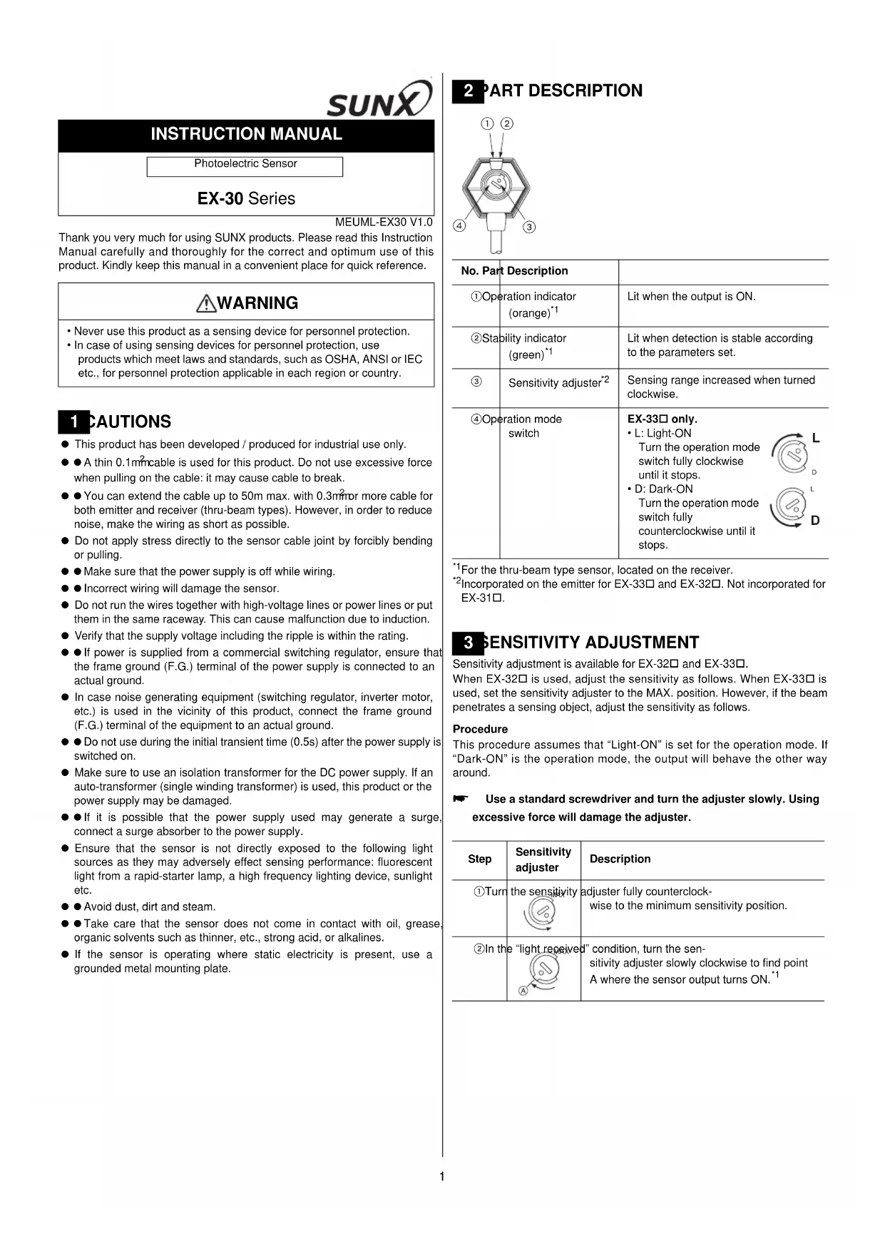
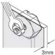
2 PART DESCRIPTION
| No. Part Description | |
| 1Operation indicator (orange) ^*1 | Lit when the output is ON. |
| 2Stability indicator (green) ^*1 | Lit when detection is stable according to the parameters set. |
| 3Sensitivity adjuster ^*2 | Sensing range increased when turned clockwise. |
| 4Operation mode switch | EX-33□ only.L: Light-ONTurn the operation mode switch fully clockwise until it stops.D: Dark-ONTurn the operation mode switch fully counterclockwise until it stops.   |
^*1 For the thru-beam type sensor, located on the receiver.
^2 Incorporated on the emitter for EX-33☐ and EX-32☐. Not incorporated for EX-31☐.
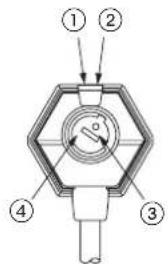
3 SENSITIVITY ADJUSTMENT
Sensitivity adjustment is available for EX-32□ and EX-33□.
When EX-32□ is used, adjust the sensitivity as follows. When EX-33□ is used, set the sensitivity adjuster to the MAX. position. However, if the beam penetrates a sensing object, adjust the sensitivity as follows.
Procedure
This procedure assumes that "Light-ON" is set for the operation mode. If "Dark-ON" is the operation mode, the output will behave the other way around.
Use a standard screwdriver and turn the adjuster slowly. Using excessive force will damage the adjuster.
^1 Remember, this only applies if the operation mode is Light-ON.
| Step | Sensitivity adjuster | Description |
| 1Turn | the sensitivity  | adjuster fully counterclockwise to the minimum sensitivity position. |
| 2In the "light received" condition, turn the sensitivity adjuster slowly clockwise to find point A where the sensor output turns ON.*1 | ||
3EX-33 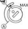 | In the “dark” condition, place an object to be sensed and turn the sensitivity adjuster clockwise until the sensor output just turns ON.Then turn the adjuster counterclockwise to find point B where the sensor just turns OFF.EX-32 In the “dark” condition, turn the sensitivity adjuster clockwise until the sensor output turns ON. ^1 Turn it back slowly to confirm point B, where the sensor output just turns OFF. ^1 If the sensor output does not turn ON even when the sensitivity adjuster is turned fully clockwise, point B is the position at MAX. | |
| 4The | position exactly MAX | between points A and Bis the optimum sensing position. |
4 MOUNTING
Mount the sensor on a mounting plate 3mm or less thick.
①Use the enclosed nut and toothed lock washer for mounting. The tightening torque should be 0.6N·m or less. (For EX-32□: 1N·m or less.)
② When tightening the nut, hold the sensor with your hand or an end wrench, for example. Do not tighten the sensor itself!
5 /O CIRCUIT DIAGRAMS
NPN output type
For the thru-beam type, the receiver incorporates the output.
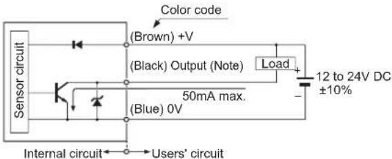
PNP output type

For the thru-beam type, the receiver incorporates the output.
6 GLIT MASK
The slit mask is only available for the thru-beam type sensor.
The optional slit mask (OS-EX30-1) helps the sensor detect small objects. The accuracy of the position being sensed is also increased. However, the sensing range is reduced.
Mounting method
The tightening torque should be 0.6N·m or less.
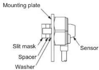
①Insert the sensor into the mounting plate.
②Fit the washer and spacers enclosed with the slit mask.
The number of spacers required depends on the thickness of the mounting plate.
| Mounting plate thickness No. of spacers | |
| 3mm 0 | |
| 2mm 1 | |
| 1mm 2 | |
③Mount the slit mask. Make sure that the tightening torque is 0.6N·m or less.
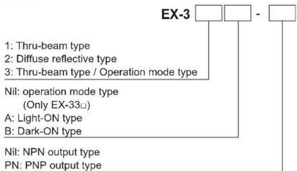
7 MODELS, ORDERING INFORMATION
flowchart
graph TD
    A["EX-3"] --> B["1: Thru-beam type"]
    A --> C["2: Diffuse reflective type"]
    A --> D["3: Thru-beam type / Operation mode type"]
    A --> E["Nil: operation mode type (Only EX-33□)"]
    E --> F["A: Light-ON type"]
    E --> G["B: Dark-ON type"]
    A --> H["Nil: NPN output type"]
    A --> I["PN: PNP output type"]
For thru-beam type sensors, the P suffix engraved on the sensor denotes the emitter, e.g.. EX-□P; D denotes the receiver, e.g. EX-□D-□.
8 SPECIFICATIONS
| Type Thru-beam type Diffuse reflective type | ||||
| Model no. | EX-31□ | EX-33□ | EX-32□ | |
| Sensing range 500mm 800mm | 50mm^*1 | |||
| Sensing object ø2mm or more opaque object Opaque, translucent or transparent object | ||||
| Supply voltage 12 to 24V DC±10% | Ripple P-P 10% or less | |||
| Current consumption | Emitter: 10mA or less, Receiver: 15mA or less | 20mA or less | ||
| Output | NPN output type | PNP output type | ||
| NPN open-collector transistor• Maximum sink current: 50mA• Applied voltage: 30V DC or less (between output and 0V)• Residual voltage: 1V or less (at 50mA sink current) | PNP open-collector transistor• Maximum source current: 50mA• Applied voltage: 30V DC or less (between output and +V)• Residual voltage: 1V or less (at 50mA source current) | |||
^*1 The sensing range is specified for white non-glossy paper (100x100mm) as the object.
SUNX Limited
URL: sunx.jp
Overseas Sales Dept. (Head Office)
2431-1 Ushiyama-cho, Kasugai-shi, Aichi, 486-0901, Japan
Phone: +81-(0)568-33-7861 FAX: +81-(0)568-33-8591
Europe Headquarter: Panasonic Electric Works Europe AG
www.panasonic-electric-works.com
Overseas Sales Dept. (Head Office)
2431-1 Ushiyama-cho, Kasugai-shi, Aichi, 486-0901, Japan
Phone: +81-(0)568-33-7861 FAX: +81-(0)568-33-8591
Europe Headquarter: Panasonic Electric Works Europe AG
www.panasonic-electric-works.com
Overseas Sales Dept. (Head Office)
2431-1 Ushiyama-cho, Kasugai-shi, Aichi, 486-0901, Japan
Phone: +81-(0)568-33-7861 FAX: +81-(0)568-33-8591
Europe Headquarter: Panasonic Electric Works Europe AG
www.panasonic-electric-works.com
MANUEL D'INSTRUCTIONS
Overseas Sales Dept. (Head Office)
2431-1 Ushiyama-cho, Kasugai-shi, Aichi, 486-0901, Japan
Phone: +81-(0)568-33-7861 FAX: +81-(0)568-33-8591
Europe Headquarter: Panasonic Electric Works Europe AG
www.panasonic-electric-works.com
Overseas Sales Dept. (Head Office)
2431-1 Ushiyama-cho, Kasugai-shi, Aichi, 486-0901, Japan
Phone: +81-(0)568-33-7861 FAX: +81-(0)568-33-8591
Europe Headquarter: Panasonic Electric Works Europe AG
www.panasonic-electric-works.com


Brand : PANASONIC
Model : EX33PN
Category : Lamp