CX412PZ - Lamp PANASONIC - Free user manual and instructions
Find the device manual for free CX412PZ PANASONIC in PDF.
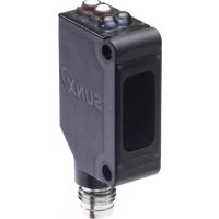
| Product type | Compact photoelectric sensor |
| Brand | Panasonic (formerly SUNX) |
| Model | CX412PZ (CX-400 series) |
| Range (through-beam version) | 10 m |
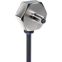
| Range (retroreflective version) | 3 m (with RF-230 reflector) |
| Range (diffuse reflection version) | 300 mm (white paper) / 800 mm (long range) / 70 to 200 mm (ultra-thin beam) |
| Detectable object (through-beam) | Minimum opaque object ∅12 mm |
| Power supply | 12 to 24 V DC ±10%, ripple ≤10% |
| Current consumption | 20 to 25 mA depending on version |
| Output | NPN or PNP open-collector, 100 mA max. |
| Operation modes | Light-ON / Dark-ON (switch) |
| Response time | ≤1 ms |
| Indicators | Operation (orange), stability (green), power (green on through-beam emitter) |
| Protection | Short-circuit, reverse polarity, overvoltage |
| Protection degree | IP67 (IEC) |
| Ambient temperature | -25 to +55 °C, storage -30 to +70 °C |
| Ambient humidity | 35 to 85% RH |
| Housing material | PBT, lens and indicator cover in acrylic |
| Cable length | 2 m (standard), extension up to 100 m possible |
| Weight | 45 to 50 g depending on version |
| Supplied accessories | RF-230 reflector (for retroreflective version) |
| Maintenance and cleaning | Clean with a dry soft cloth. Do not use organic solvents. |
| Safety | Do not use for personnel protection. Observe wiring and installation precautions. |
Frequently Asked Questions - CX412PZ PANASONIC
User questions about CX412PZ PANASONIC
0 question about this device. Answer the ones you know or ask your own.
Ask a new question about this device
Download the instructions for your Lamp in PDF format for free! Find your manual CX412PZ - PANASONIC and take your electronic device back in hand. On this page are published all the documents necessary for the use of your device. CX412PZ by PANASONIC.
USER MANUAL CX412PZ PANASONIC
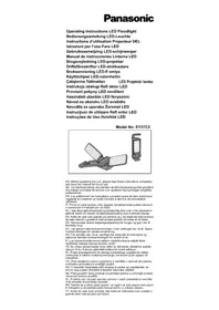
Thank you very much for using SUNX products. Please read this Instruction Manual carefully and thoroughly for the correct and optimum use of this product. Kindly keep this manual in a convenient place for quick reference.

WARNING
- Never use this product as a sensing device for personnel protection.
- In case of using sensing devices for personnel protection, use products which meet laws and standards, such as OSHA, ANSI or IEC etc., for personnel protection applicable in each region or country.
1 CAUTIONS
● Make sure to carry out wiring with the power OFF.
- Incorrect wiring will damage the sensor.
- Verify that the supply voltage including the ripple is within the rating.
- If power is supplied from a commercial switching regulator, ensure that the frame ground (F.G.) terminal of the power supply is connected to an actual ground.
- In case noise generating equipment (switching regulator, inverter motor, etc.) is used in the vicinity of this product, connect the frame ground (F.G.) terminal of the equipment to an actual ground.
- Do not run the wires together with high-voltage lines or power lines or put them in the same raceway. This can cause malfunction due to induction.
- Do not use during the initial transient time (50ms) after the power supply is switched on.
● ● This sensor is suitable for indoor use only.
- ● You can extend the cable up to 100m max. with 0.3mm or more cable. However, in order to reduce noise, make the wiring as short as possible.
- Do not apply stress directly to the sensor cable joint by forcibly bending or pulling.
- Do not use this sensor in places having excessive vapor, dust, etc., or where it may come in direct contact with water or corrosive gas.
● Take care that the sensor does not come in direct contact with water, oil grease, or organic solvents such as thinners, etc.
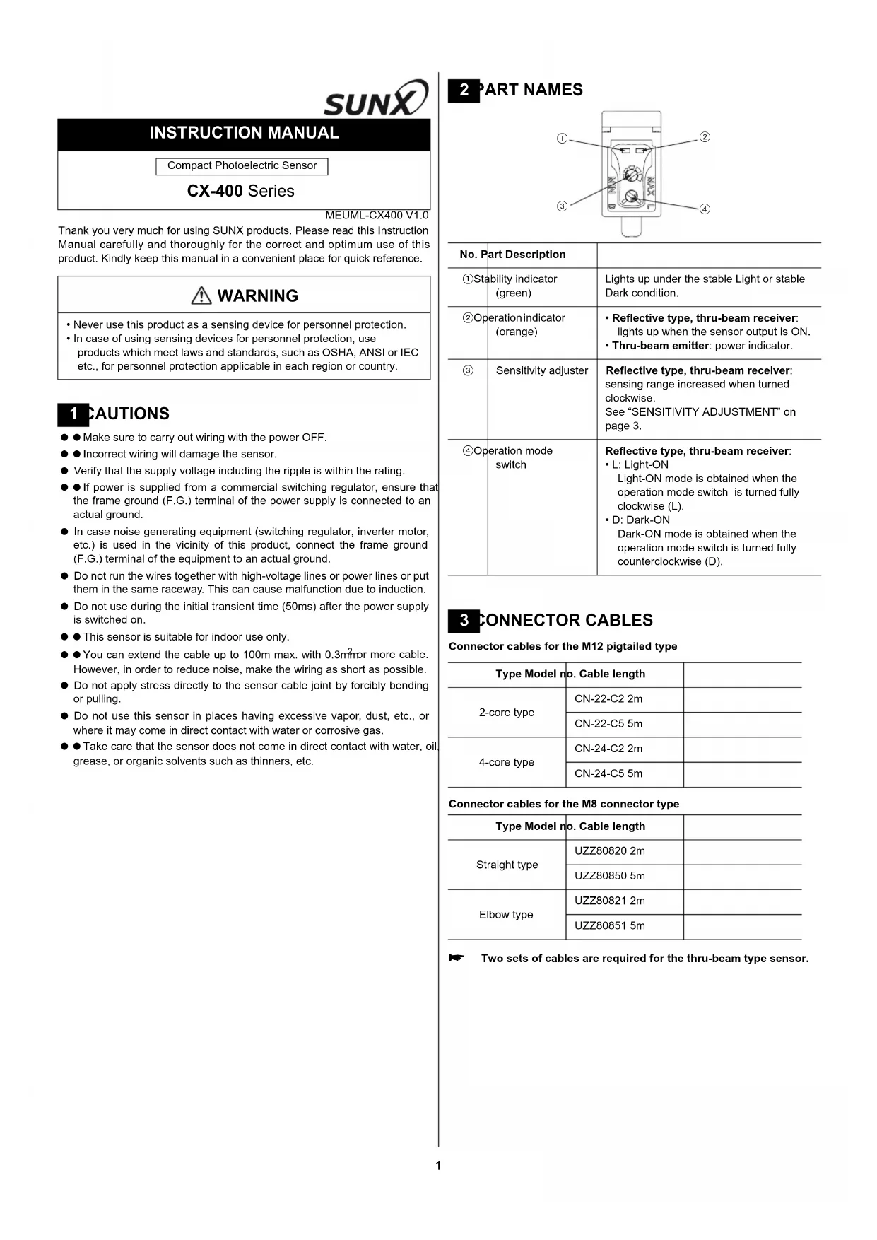
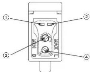
2 PART NAMES
text_image
Diagram of a device control panel with numbered labels pointing to key components| No. | Part Description | |
| 1 | Stability indicator (green) | Lights up under the stable Light or stable Dark condition. |
| 2 | Operation indicator (orange) | Reflective type, thru-beam receiver: lights up when the sensor output is ON.Thru-beam emitter: power indicator. |
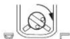
| 3 | Sensitivity adjuster | Reflective type, thru-beam receiver: sensing range increased when turned clockwise.See "SENSITIVITY ADJUSTMENT" on page 3. |
| 4 | Operation mode switch | Reflective type, thru-beam receiver:L: Light-ONLight-ON mode is obtained when the operation mode switch is turned fully clockwise (L).D: Dark-ONDark-ON mode is obtained when the operation mode switch is turned fully counterclockwise (D). |
3 CONNECTOR CABLES
Connector cables for the M12 pigtailed type
| Type Model no. Cable length | ||
| 2-core type | CN-22-C2 2m | |
| CN-22-C5 5m | ||
| 4-core type | CN-24-C2 2m | |
| CN-24-C5 5m | ||
Connector cables for the M8 connector type
| Type Model no. Cable length | ||
| Straight type | UZZ80820 2m | |
| UZZ80850 5m | ||
| Elbow type | UZZ80821 2m | |
| UZZ80851 5m | ||
Two sets of cables are required for the thru-beam type sensor.
4 /O CIRCUIT DIAGRAMS
The following symbols are used in this section.
| Symbol Meaning | |
| D Reverse supply polarity protection diode | |
| ZD Surge absorption zener diode | |
| Tr NPN / PNP output transistor |
Pin assignment
| M12 pigtailed type Terminal name M8 connector type | ||
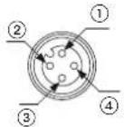 | 1) +V2) Not connected3) 0V4) Output (see note) |  |
Only the thru-beam receiver incorporates the output.
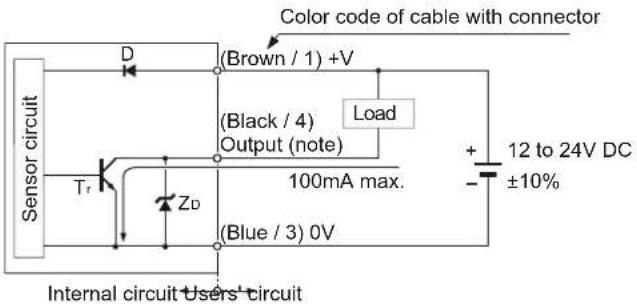
NPN output type
text_image
Color code of cable with connector Sensor circuit D (Brown / 1) +V (Black / 4) Output (note) Load Tr ZD 100mA max. (Blue / 3) 0V Internal circuit Users' circuit + 12 to 24V DC - ±10%Only the thru-beam receiver incorporates the output.
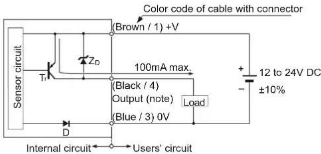
PNP output type
text_image
Color code of cable with connector (Brown / 1) +V 100mA max. (Black / 4) Output (note) (Blue / 3) 0V Load + - 12 to 24V DC ±10% Sensor circuit Tr ZD D Internal circuit Users' circuitOnly the thru-beam receiver incorporates the output.
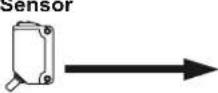
5 MOUNTING AND ADJUSTING
Mount the sensor with a tightening torque of 0.5N·m or less.
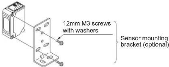
text_image
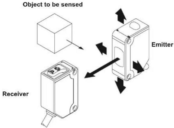
12mm M3 screws with washers Sensor mounting bracket (optional)Thru-beam type sensor
①Set the operation mode switch to the Light-ON mode position (L side).
②Placing the emitter and the receiver face to face along a straight line. Move the emitter up, down, left and right to determine where light is received with the help of the receiver's operation indicator (orange). Set the emitter in the middle of this area.
③Adjust the angle of the emitter by twisting it up, down, left and right.
④In a similar manner, adjust the angle of the receiver.
⑤Check that the stability indicator (green) lights up.
⑥ Choose the desired operation mode, Light-ON or Dark-ON, with the operation mode switch.
text_image
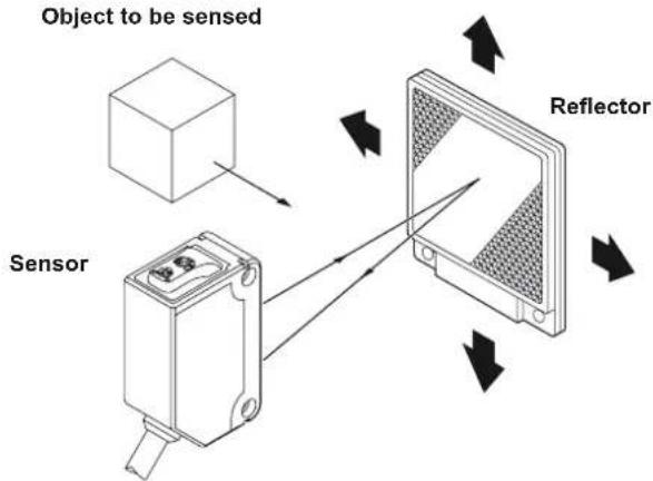
Object to be sensed Receiver EmitterRetroreflective type sensor
Make sure to mount the sensor and the reflector at least 0.1mm apart.
①Set the operation mode switch to the Light-ON mode position (L side).
② Placing the sensor and the reflector face to face along a straight line. Move the reflector up, down, left and right to determine where light is received the help of the operation indicator (orange). Set the reflector in the middle of this area.
③Adjust the angle of the reflector by twisting it up, down, left and right.
④In a similar manner, adjust the angle of the sensor.
⑤Check that the stability indicator (green) lights up.
⑥ Choose the deisred operation mode, Light-ON or Dark-ON, with the operation mode switch.
text_image
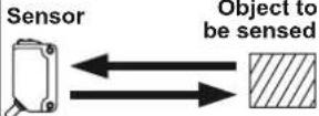
Object to be sensed Sensor Reflector6 SENSITIVITY ADJUSTMENT
To understand sensitivity adjustment, you must first understand the difference between the "light received" and the "dark" condition.
Do not confuse the "light received" and "dark" condition with the operation modes "Light-ON" and "Dark-ON"!
| Thru-beamRetroref | Light received condition Dark condition | ||
 | Object to be sensed 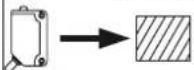 | ReceiverB  | |
Sensor Reflector 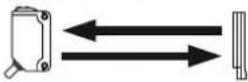 | Sensor Object to be sensed 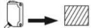 | Reflector [2014] | |
 |  | ||
Relationship between output and indicators
| Light-ON Dark-ON | ||||||
| Stability indicator | Operation indicator | Output | Sensing condition | Output | Operation indicator | Stability indicator |
| ON | Stable light | OFF | ||||
| Unstable light | ||||||
| OFF | Unstable dark | ON | ||||
| Stable dark | ||||||
⊙= lit, ●= unlit
Use a standard screwdriver and turn the adjuster slowly. Using excessive force will damage the adjuster.
This procedure assumes that "Light-ON" is set for the operation mode.
If "Dark-ON" is the operation mode, the output will behave the other way around!
| Step | Sensitivity adjuster | Description |
| 1Turnitter | the sensitivity adjuster fully counter-clockwise to the minimum sensitivity position, MIN. | |
| 2In the "light received" condition, turn the sensitivity adjuster slowly clockwise to find point A where the sensor output turns ON.*1 | ||
| 3In the position, turn the sensitivity adjuster clockwise until the sensor output turns ON.*1 | ||
| 4The position exactly between points A and B is the optimum sensing position. | ||
^*1 Remember, this only applies if the operation mode is Light-ON.
7 AUTOMATIC INTERFERENCE PREVENTION FUNCTION
This function is not available for the thru-beam type sensor. See "INTERFERENCE PREVENTION FILTERS" on page 4.
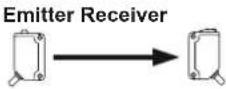
The automatic interference prevention function allows you to mount up to two sets of sensors next to each other.
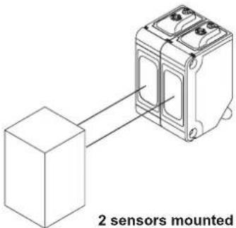
text_image
2 sensors mounted2 sensors mounted closely together
8
RETROREFLECTIVE TYPE SENSOR WITH POLARIZING FILTERS
As light is polarized by a transparent film or membrane, CX-491 may not detect an object covered or wrapped by transparent film. Such objects include, for example:
● Can wrapped by clear film
● ● Aluminum sheet covered by plastic film
● Gold or silver (glossy) labels or wrapping paper
In such cases, take the following steps.
①Tilt the sensor with respect to the object to be sensed.
②Reduce the sensitivity.
③ Increase the distance between the sensor and the object to be sensed.
9
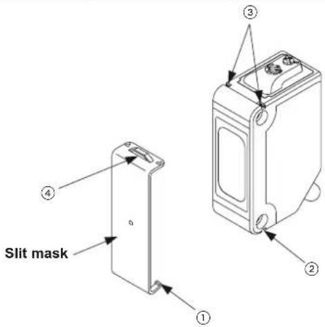
SLIT MASKS

The slit mask is only available for the thru-beam type sensor.
Optional slit masks help the sensor detect small objects. However, the sensing range is reduced.
| Type Model no. | Slit size | |
| Round slit mask | OS-CX-05 = 0.5mm | |
| OS-CX-1 = 1mm | ||
| OS-CX-2 = 2mm | ||
| Rectangular slit mask | OS-CX-05 x 6 0.5 × 6mm | |
| OS-CX-1 x 6 1 × 6mm | ||
| OS-CX-2 x 6 2 × 6mm | ||
text_image
Slit mask ① ② ③How to mount
①Insert the hook (1) into the bottom groove (2).
② Press the slit mask until it snaps into the grooves (3) on the top of the main unit.
How to remove
①Insert a screw driver into the tab (4).
②Lift and remove carefully.
10
NTERFERENCE PREVENTION FILTERS
Interference prevention filters are only available for the thru-beam type sensor.
By mounting interference prevention filters, two sets of thru-beam type sensors can be mounted close together. However, the sensing range is reduced.
The filters can be mounted using the same method as for slit masks. For details, see page 4, section 9, SLIT MASKS.
For interference prevention to work, the following conditions must be met.
● The two sets of sensors must be fitted with different types of interference prevention filters.
● Filters must be mounted on emitters and receivers.
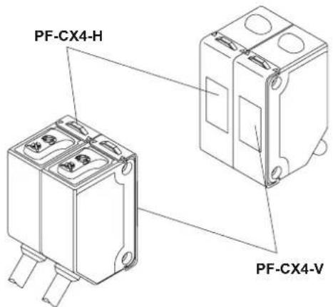
text_image
PF-CX4-H PF-CX4-V| Model no. | Direction of thru-beam axis | Color of the bracket |
| PF-CX4-H Horizontal | Light brown | |
| PF-CX4-V | Vertical | Silver |

The model no. is not shown on the interference prevention filters. Take care when mounting them on the sensors.
11 SPECIFICATIONS
| Item | Thru-beam | Retroreflective type with polarizing filter*1 | Diffuse reflective | Narrow view reflective | ||
| Short sensing range | Long sensing range | |||||
| CX-411 (NPN)*2 | CX-491 (NPN)*2 | CX-421 (NPN)*2 | CX-422 (NPN)*2 | CX-423 (NPN)*2 | ||
| CX-411-P (PNP)*2 | CX-491-P (PNP)*2 | CX-421-P (PNP)*2 | CX-422-P (PNP)*2 | CX-423-P (PNP)*2 | ||
| Sensing range | 10m | 3m^*3 | 300mm^*4 | 800mm^*4 | 70 to 200mm^*4 | |
| Object to be sensed | ∅ 12mm or more opaque object | ∅ 50mm or more opaque, translucent or specular object*3 | Opaque, translucent or specular Opaque, translucent or transparent object (Min. ∅ 0.5mm copper wire) | |||
| Repeatability(perpendicular to sensing axis) | 0.5mm or less 1mm or less 0.5mm or less | less | ||||
| Supply voltage | 12 to 24V DC ±10% Ripple P-P 10% or less | |||||
| Current consumption | Emitter: 20mA or lessReceiver: 20mA or less | 20mA or less 25mA or less 20mA or less | ||||
| Output | NPN output type• NPN open-collector transistor• Maximum sink current: 100mA• Applied voltage: 30V DC or less (between output and 0V)• Residual voltage: 1V or less (at 100mA sink current), 0.4V or less (at 16mA sink current) | PNP output type• PNP open-collector transistor• Maximum source current: 100mA• Applied voltage: 30V DC or less (between output and +V)• Residual voltage: 1V or less (at 100mA source current), 0.4V or less (at 16mA source current) | ||||
| Output operation | Light-ON or Dark-ON | |||||
| Short-circuit protection | Incorporated | |||||
| Response time 1ms or less | ||||||
| Operation indicator | Orange LED, lights up when the output is ON. Thru-beam type sensor: located on the receiver. | |||||
| Stability Indicator | Green LED, lights up under stable light received condition or stable dark condition. Thru-beam type sensor: located on the receiver | |||||
| Power indicator | Green LED, lights up when the power is ON.Located on the emitter | ____ | ||||
| Sensitivity adjuster Available. | ||||||
| Automatic interference prevention function | ____*5 | Incorporated, two sets of sensors can be mounted close together. | ||||
| Protection IP67 (IEC) | ||||||
| Ambient temperature | -25 to +55°C (No dew condensation or icing allowed), Storage: -30 to +70°C | |||||
| Ambient humidity 35 to 85% RH, Storage: 35 to 85% RH | ||||||
| Emitting element | Red LED (modulated) Infrared LED (modulated) | Red LED | (modulated) | |||
| Material | Enclosure: PBT, Lens: Acrylic, Indicator cover: Acrylic | |||||
| Cable | 0.2mm^2 3-core (thru-beam type sensor emitter: 2-core) cabtyre cable, 2m long | |||||
| Weight | Emitter: 45g approx.Receiver: 50g approx. | 50g approx. | ||||
| Accessory | ____ | RF-230 (Reflector): 1 pc. | ____ | |||
^1 The retroreflective type sensor with polarizing filters may not stably detect specular or glossy objects through transparent film since light is polarized by the transparent film. For details, see page 4, section 8, RETROREFLECTIVE TYPE SENSOR WITH POLARIZING FILTERS.
^2 Model nos. with the suffix -J indicate the M12 pigtailed type. The suffix -Z indicates the M8 connector type.
^3 The sensing range and the sensing object for the retroreflective type sensor is specified for the RF-230 reflector.
^*4 The sensing range of the diffuse reflective type sensor and the narrowview reflective type sensor is specified for white non-glossy paper (200 x 200mm).
*5 By mounting interference prevention filters, two sets of the sensors can be mounted close together. For details, see page 4, section 10, INTERFERENCE PREVENTION FILTERS.
SUNX Limited
URL: sunx.jp
Overseas Sales Dept. (Head Office)
2431-1 Ushiyama-cho, Kasugai-shi, Aichi, 486-0901, Japan
Phone: +81-(0)568-33-7861 FAX: +81-(0)568-33-8591
Europe Headquarter: Panasonic Electric Works Europe AG
www.panasonic-electric-works.com
text_image
Diagram of a device control panel with labeled parts including buttons and indicatorsREFLEXIONS-LLCHTSCHRANKE MIT POLARISATIONSFILTERN
Overseas Sales Dept. (Head Office)
2431-1 Ushiyama-cho, Kasugai-shi, Aichi, 486-0901, Japan
Phone: +81-(0)568-33-7861 FAX: +81-(0)568-33-8591
Europe Headquarter: Panasonic Electric Works Europe AG
www.panasonic-electric-works.com
text_image
Diagram of a device control panel with numbered labels pointing to internal componentsMANUEL D'INSTRUCTIONS
text_image
Diagram of a device control panel with labeled parts ①, ②, and ③text_image
Diagram of a device control panel with numbered labels pointing to ports and buttonsOverseas Sales Dept. (Head Office)
2431-1 Ushiyama-cho, Kasugai-shi, Aichi, 486-0901, Japan
Phone: +81-(0)568-33-7861 FAX: +81-(0)568-33-8591
Europe Headquarter: Panasonic Electric Works Europe AG
www.panasonic-electric-works.com