
CX422P - Lamp PANASONIC - Free user manual and instructions
Find the device manual for free CX422P PANASONIC in PDF.


| Product Type | LED Ceiling Lamp |
| Model | CX422P |
| Brand | Panasonic |
| Light Source | LED (non-replaceable) |
| Luminous Flux | 1600 lm |
| Color Temperature | 3000K - 6500K (adjustable) |
| Power Consumption | 18 W |
| Input Voltage | 100-240V AC, 50/60 Hz |
| Dimensions (LxWxH) | 400 x 400 x 100 mm |
| Weight | 1.2 kg |
| Mounting Type | Ceiling flush mount |
| Material | Aluminum + Acrylic |
| Protection Class | Class II |
| IP Rating | IP20 |
| Dimmable | Yes (with compatible dimmer) |
| Remote Control | Included |
| Color Rendering Index (CRI) | ≥80 |
| Lifespan | 40000 hours |
| Operating Temperature | -10°C to +40°C |
| Certifications | CE, RoHS |
| Warranty | 2 years |
| Cleaning Instructions | Wipe with dry cloth; do not use liquids |
| Spare Parts Available | Remote control, mounting kit |
Frequently Asked Questions - CX422P PANASONIC
User questions about CX422P PANASONIC
0 question about this device. Answer the ones you know or ask your own.
Ask a new question about this device
Download the instructions for your Lamp in PDF format for free! Find your manual CX422P - PANASONIC and take your electronic device back in hand. On this page are published all the documents necessary for the use of your device. CX422P by PANASONIC.
USER MANUAL CX422P PANASONIC
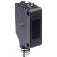
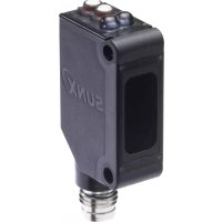
Compact Photoelectric Sensor
CX-400 SERIES
Related Information
General terms and conditions .....P.1
SUNX website http://www.sunx.com


World standard photoelectric sensors Full line up 116 models!
Wide variety of 116 models
You can find your desired sensors among the CX-400 series because of their high basic performance, superior cost performance, and wide variation of types.
Type Sensing range
Output
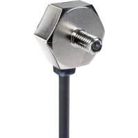
Connecting method (Note 1) Cable type, M8 Plug-in connector type, M12 Pigtailed type
Cable length of cable type (Note 2) 0.5 m 1.640 ft, 2 m 6.562 ft, 5 m 16.404 ft
Notes: 1) The adjustable range reflective type includes the cable type and M8 connector type only.
2) The adjustable range reflective type includes the 2 m 6.562 ft cable type (standard) only.
Strong against oil and coolant liquids
CX-414249
The lens material for the thru-beam type, retroreflective type (excluding the CX-48) and the diffuse reflective type are made of a strong acrylic that resists the harmful effects of coolants. These sensors can be used with confidence even around metal processing machinery that disperses oil mists. The protection mechanism also

Strong against ethanol
CX-44/48
A strong, ethanol resistant polycarbonate was used for the front and display covers. Safe even for installing near food processing machinery that disperses ethanol based detergents. The protection mechanism also conforms to IP67 (IEC).

Caution: Set the CX-48X so that cleaning liquid will not get on to the attached reflector.
APPLICATIONS
Detecting out of position tape feeder cassette
Detecting objects in places that have a lot of dust or clouds of particles
Passage confirmation of object on a conveyor belt
Detecting transparent glass bottles
Small tablet sensing Biscuit sensing

BASIC PERFORMANCE
Strong infrared beam
CX-412
The longest in its class, it realizes a 15 m 49.213 ft long-distance sensing range. Remarkable penetrating power enables applications such as package content detection. (Note)

Note: When sensing utilizing penetrating power, make sure to verify using the actual sensor.
Hardly affected by color
CX-441/443
Both black and white objects can be sensed at the same distances. No adjuster control is needed, even when products of different colors are moving along the production line.

The difference in sensing ranges is 1% or less between non-glossy white paper with a setting distance of 50 mm 1.969 in and non-glossy gray paper with a brightness level of 5.
Can sense differences as small as 0.4 mm 0.016 in,
with hysteresis of 2 % or less
CX-441/443
An advanced optical system provides sensing performance that is 2.5 times approx. than conventional models. Even ultra-small differences of 0.4 mm 0.016 in can be detected accurately.
2.5 times the sensing capability!
Height differences of as little as 0.4 mm 0.016 in can be detected at a setting distance of 20 mm 0.787 in

Retroreflective type with polarizing filters
CX-491
Built-in polarizing filters ensure stable sensing even on a specular object.

FIBER SENSORS
LASER SENSORS
PHOTOELECTRIC SENSORS
MICRO PHOTOELECTRIC SENSORS
AREA SENSORS
SAFETY COMPONENTS
PRESSURE SENSORS
INDUCTIVE PROXIMITY SENSORS
PARTICULAR USE SENSORS
SENSOR OPTIONS
WIRE-SAVING SYSTEMS
MEASUREMENT SENSORS
STATIC CONTROL DEVICES
LASER MARKERS
Selection Guide
Amplifier Built-in
CX-400
EX-10
EX-20
EX-30
EX-40
EQ-30
EQ-500
MQ-W
RX-LS200
RX
CY
PX-2
RT-610
Power Supply Built-in
NX5
VF
Amplifier-separated
SU-7 / SH
SS-A5 / SH
Other Products
FIBER SENSORS
LASER SENSORS
PHOTOELECTRIC SENSORS
MICRO PHOTOELECTRIC SENSORS
AREA SENSORS
SAFETY COMPONENTS
PRESSURE SENSORS INDUCTIVE PROXIMITY SENSORS
PARTICULAR USE SENSORS
SENSOR OPTIONS
WIRE-SAVING SYSTEMS
MEASUREMENT SENSORS
STATIC CONTROL DEVICES
LASER MARKERS
Selection Guide
Amplifier Built-in
CX-400
EX-10
EX-20
EX-30
EX-40
EQ-30
EQ-500
MQ-W
RX-LS200
RX
CY
PX-2
RT-610
Power Supply Built-in
NX5
VF
Amplifier-separated
SU-7 / SH
SS-A5 / SH
Other Products
BASIC PERFORMANCE
Introducing the transparent object sensing type sensor
Our unique optical system and transparent object sensing circuitry provide stable sensing of even thinner transparent objects than the conventional models.

Long sensing range of 5 m 16.404 ft
A long sensing range of 5 m (16.404 ft) is possible with the red LED type that is easy to align with the beam axis. Can be used for wide automatic door shutters.

CX-48
Transparent objects detectable with CX-48 (Typical examples)
| Sensing object Sensing object size (mm in) | ||
| Glass sheet | 50 1.969 | t = 0.7 0.028 |
| Cylindrical glass | ø50 ø1.969 = 50 1.969 | t = 1.3 0.051 |
| Acrylic board | 50 1.969 | t = 1.0 0.039 |
| Styrol (Floppy case) | 50 1.969 | t = 0.9 0.035 |
| Food wrapping film | 50 1.969 | t = 10 μm 0.394 mil |
| Cigarette case film | 50 1.969 | t = 20 μm 0.787 mil |
| Vinyl sack | 50 1.969 | t = 30 μm 1.181 mil |
| Pet bottle (500ml) | ø66 ø2.598 | |
Reflector setting range: CX-481: 300 to 500 mm (11.811 to 19.685 in), CX-482: 1 to 2 m (3.281 to 6.562 ft)
[with the RF-230 reflector at the optimum condition (Note)] Each object should pass across the beam at the center between the sensor and the reflector.
l: Length of cylindrical glasses t: Thickness of sensing object
Note: The optimum condition is defined as the condition in which the sensitivity level is set such that the stability indicator just lights up when the object is absent.
Less power consumed
The CX-400 series sensors achieve a maximum of approximately 55% of the power consumption of conventional sensors. Contributes to preserving the environment.

ENVIRONMENTAL RESISTANCE
Strong on dust and dirt
CX-412
Because the light source is an infrared light, it is strong on dust and dirt compared to the red beam type.

Strong even in cold environments
Stable performance can be maintained even in environments of -25°C (-13°F).
Strong against noise
Significantly stronger against inverter light and other extraneous light as well as high frequency and electromagnetic noise generated by high-pressure inverter motors and other devices.

MOUNTING
Beam axis alignment made easy with a high luminance spot beam
CX-423
These sensors realize a high luminance red LED spot that provides bright visibility enabling the sensing position to be checked at a glance. Because it has the smallest spot in its class, Ø 2 mm (Ø 0.079 in) approx., even the minutest object can be accurately detected.

Great visibility approx. Ø 2 mm (Ø 0.079 in) high luminance spot (at setting distance 100 mm 3.937 in)
The bright spot makes beam axis alignment easy
CX-44
These sensors realize a high luminance red spot that provides bright visibility. The sensing position can be checked at a glance. Because the CX-441 sensor has the smallest spot in its class Ø 2 mm (Ø 0.079 in) approx., even the minutest object can be accurately detected.

OPERABILITY
Reduction of volume adjustment labor
CX-42
Because these sensors possess many variations depending on the sensing range, enables you to make optimal volume adjustment easily.
CX-422: 800 mm 31.496 in CX-421: 300 mm 11.811 in CX-424: 100 mm 3.937 in

CX-423: 70 to 200 mm 2.756 to 7.874 in
Can be used for sensing minute differences
Equipped with a 5-turn adjuster so that even challenging range settings can be handled with ease.

VARIETIES
Less processing
M8 plug-in connector type and M12 pigtailed type are available. This contributes to less time spent in setting up. In addition, cable types are available with cable lengths of 0.5 m 1.640 ft, 2 m 6.562 ft and 5 m 16.404 ft. This results in less wastage.
No unnecessary cables or terminal blocks
Select from 2 spot diameters as per the application
CX-441/443
Within the choice of 50 mm 1.969 in sensing range sensors, we offer small spot approx. ø2 mm ø0.079 in type optimal for detecting minute object and large approx. ø6.5 mm ø0.256 in spot type capable of sensing object covered with holes and grooves.

CX-441
Spot diameter: ø2 mm
∅0.079 in
approx.
[Positioning]
Detects minute holes.
CX-443
Spot diameter: ø6.5 mm
∅0.256 in
approx.
I Detection of presence /
absence of objects
Ignores minute holes and
accurately detects objects.
FIBER SENSORS
LASER SENSORS
PHOTOELECTRIC SENSORS
MICRO PHOTOELECTRIC SENSORS
AREA SENSORS
SAFETY COMPONENTS
PRESSURE SENSORS
INDUCTIVE PROXIMITY SENSORS
PARTICULAR USE SENSORS
SENSOR OPTIONS
WIRE-SAVING SYSTEMS
MEASUREMENT SENSORS
STATIC CONTROL DEVICES
LASER MARKERS
Selection Guide
Amplifier Built-in
CX-400
EX-10
EX-20
EX-30
EX-40
EQ-30
EQ-500
MQ-W
RX-LS200
RX
CY
PX-2
RT-610
Power Supply Built-in
NX5
VF
Amplifier-separated
SU-7 / SH
SS-A5 / SH
Other Products
FIBER SENSORS
LASER SENSORS
PHOTOELECTRIC SENSORS
MICRO PHOTOELECTRIC SENSORS
AREA SENSORS
SAFETY COMPONENTS
PRESSURE SENSORS / INDUCTIVE PROXIMITY SENSORS
PARTICULAR USE SENSORS
SENSOR OPTIONS
WIRE-SAVING SYSTEMS
MEASUREMENT SENSORS
STATIC CONTROL DEVICES
LASER MARKERS
FUNCTIONS
BGS / FGS functions make even the most challenging settings possible!
CX-44
For details on the operation of the BGS / FGS functions, refer to p.249, "BGS / FGS functions" of "PRECAUTIONS FOR PROPER USE".
The BGS function is best suited for the following case
Background not present
When object and background are separated
BGS

Not affected if the background color changes or someone passes behind the conveyor.


The FGS function is best suited for the following case
Background present
When object and background are close together When the object is glossy or uneven
FGS

Unaffected by gloss, color or uneven surfaces when sensing objects present on a conveyor belt.

BGS (Background suppression) function
The sensor judges that an object is present when light is received at position A of the light-receiving element (2-segment element).
This is useful if the object and background are far apart. The distance adjustment method is the same as the conventional adjustment method for adjustable range reflective type sensors.
![graph LR A["Background"] --> B["In the back"] B --> C{Setting distance} C --> D["ObjectMoving object"] D --> E["Element A"] D --> F["Element B"] G["ON/OFF"] --> H["(Light received at element A)"] H --> I["Light received at element B, or light not received"]](/content/2026/06/1359661/images/f4e7ed3474ef715328e2b1c73a38eeaa4885c0c13d5a9b3f5746bf03bedbbafa.jpg)
FGS (Foreground suppression) function
The sensor judges that an object is present when no light is received at position B of the light-receiving element (2-segment element). Accordingly, even objects that are glossy can be sensed. This is useful if the object and background are close together, or if the object being sensed is glossy.
OFF in this condition only
Object absent
Conveyor Conveyor
Light received at position B
(A conveyor or other background must be present)
ON in all other conditions
Object present Conveyor
Light received at position A
For glossy object
Light is not received at position B, so an object is judged to be present
Strong against interference
The interference prevention function lets two sensors be mounted close together precisely.

Retroreflective type, Diffuse reflective type, Adjustable range reflective type
OTHERS
Less resources used
Based on environmental considerations, simplified packaging is used in order to reduce waste. In addition, the bag is made from polyethylene which produces no toxic gases even when burned.

ORDER GUIDE
| Type Appearance Sensing range | Model No. (Note 1) | Emitting element | ||||
| NPN output PNP | output | |||||
| Thru-beam |  | 10 m 32.808 ft | CX-411 CX-411-P | Red LED | ||
| 15 m 49.213 ft | CX-412 CX-412-P | Infrared LED | ||||
| Retroreflective | Long sensing range | |||||
| With powerizing fibers |  | 3 m 9.843 ft (Note 2) | CX-491 CX-491-P | Red LED | ||
| Long sensing range | 5 m 16.404 ft (Note 2) | CX-493 CX-493-P | ||||
| For transparent object sensing | 50 to 500 mm 1.969 to 19.685 in (Note 2) | CX-481 CX-481-P | Infrared LED | |||
| 0.1 to 2 m 0.328 to 6.562 ft (Note 2) | CX-482 CX-482-P | |||||
| Diffuse reflective |  | 100 mm 3.937 in | CX-424 CX-424-P | Infrared LED | ||
| 300 mm 11.811 in | CX-421 CX-421-P | |||||
| 800 mm 31.496 in | CX-422 CX-422-P | |||||
| Narrow-view |  | 70 to 200 mm 2.756 to 7.874 in | CX-423 CX-423-P | Red LED | ||
| Adjustable range reflective | Small spot |  | 2 to 50 mm 0.079 to 1.969 in | CX-441 CX-441-P | Red LED | |
| CX-443 CX-443-P | ||||||
| 15 to 100 mm 0.591 to 3.937 in | CX-444 CX-444-P | |||||
| 20 to 300 mm 0.787 to 11.811 in | CX-442 CX-442-P | |||||
NOTE: Mounting bracket is not supplied with the sensor. Please select from the range of optional sensor mounting brackets.
Notes: 1) The model No. with suffix "E" shown on the label affixed to the thru-beam type sensor is the emitter, "D" shown on the label is the receiver. (e.g.) Emitter of CX-411: CX-411E, Receiver of CX-411: CX-411D 2) The sensing range of the retroreflective type sensor is specified for the RF-230 reflector. The sensing range represents the actual sensing range of the sensor. The sensing ranges itemized in "A" of the table below may vary depending on the shape of sensing object. Be sure to check the operation with the actual sensing object.

| CX-491CX-493CX-481CX-482 | ☒ | |||
| A | 0 to 3 m0 to 9.843 ft | 0 to 5 m0 to16.404 ft | 50 to 500 mm1.969 to 19.685 in | 0.1 to 2 m0.328 to 6.562 ft |
| B | 0.1 to 3 m0.328 to 9.843 ft | 0.1 to 5 m0.328 to 16.404 ft | 100 to 500 mm3.937 to 19.685 in | 0.8 to 2 m2.625 to 6.562 ft |
FIBER SENSORS
LASER SENSORS
PHOTOELECTRIC SENSORS
MICRO PHOTOELECTRIC SENSORS
AREA SENSORS
SAFETY COMPONENTS
PRESSURE SENSORS
INDUCTIVE PROXIMITY SENSORS
PARTICULAR USE SENSORS
SENSOR OPTIONS
WIRE-SAVING SYSTEMS
MEASUREMENT SENSORS
STATIC CONTROL DEVICES
LASER MARKERS
Selection Guide
Amplifier Built-in
CX-400
EX-10
EX-20
EX-30
EX-40
EQ-30
EQ-500
MQ-W
RX-LS200
RX
CY
PX-2
RT-610
Power Supply Built-in
NX5
VF
Amplifier-separated
SU-7 / SH
SS-A5 / SH
Other Products
ORDER GUIDE
0.5 m 1.640 ft / 5 m 16.404 ft cable length types
0.5 m 1.640 ft / 5 m 16.404 ft cable length types (standard: 2 m 6.562 ft) are also available.
When ordering this type, suffix "-C05" for the 0.5 m 1.640 ft cable length type, "-C5" for the 5 m 16.404 ft cable length type to the model No.
(Please note that 0.5 m 1.640 ft cable length type and 5 m 16.404 ft cable length type are not available for CX-44)
(e.g.) 0.5m 1.640 ft cable length type of CX-411-P is "CX-411-P-C05"
5 m 16.404 ft cable length type of CX-411-P is "CX-411-P-C5"
M8 plug-in connector type, M12 pigtailed type
M8 plug-in connector type and M12 pigtailed type are also available.
When ordering this type, suffix "-Z" for the M8 connector type, "-J" for the M12 pigtailed type to the model No.
(Please note that M12 pigtailed type is not available for CX-44☐.)
(e.g.) M8 connector type of CX-411-P is "CX-411-P-Z"
M12 pigtailed type of CX-411-P is "CX-411-P-J"
Mating cable (2 cables are required for the thru-beam type.)
| Type Model No. | Cable length Description | |||
| For M8 plug-in connector type | Straight | CN-24A-C2 | 2 m 6.562 ft | Can be used with all models |
| CN-24A-C5 | 5 m 16.404 ft | |||
| Elbow | CN-24AL-C2 | 2 m 6.562 ft | ||
| CN-24AL-C5 | 5 m 16.404 ft | |||
| For M12 pigtailed type | 2-core | CN-22-C2 | 2 m 6.562 ft | For thru-beam type emitter (2-core) |
| CN-22-C5 | 5 m 16.404 ft | |||
| 4-core | CN-24-C2 | 2 m 6.562 ft | Can be used with all models | |
| CN-24-C5 | 5 m 16.404 ft | |||
Package without reflector
NPN output type: CX-491-Y
PNP output type: CX-491-P-Y
Accessory
RF-230 (Reflector)

Mating cable
CN-22-C2, CN-22-C5, CN-24-C2, CN-24-C5
OPTIONS
| Designation | Model No. | Slit size | Sensing range Min. sensing | object | |||
| Slit Sensor | Slit on one side | Slit on both sides | Slit on one side | Slit on both sides | |||
| Round slit mask(For thru-beam type sensor only) | OS-CX-05 | CX-411 ☒ | ø0.5 mmø0.020 in | 400 mm 15.748 in 20 | mm 0.787 in | ø12 mmø0.472 inø0.5 | mmø0.020 in |
| CX-412☒ | 600 mm 23.622 in 30 | mm 1.181 in | |||||
| OS-CX-1 | CX-411☒ | ø1 mmø0.039 in | 900 mm 35.433 in 100 | mm 3.937 in | ø12 mmø0.472 in | ø1 mmø0.039 in | |
| CX-412☒ | 1.35 m 4.429 ft | 150 mm 5.906 in | ø1.5 mmø0.059 in | ||||
| OS-CX-2 | CX-411☒ | ø2 mmø0.079 in | 2 m 6.562 ft 400 mm | 15.748 in | ø12 mmø0.472 in8 in | ø2 mmø0.079 in | |
| CX-412☒ | 3 m 9.843 ft 600 mm | 23.622 inø3 mmø0.11 | |||||
| Rectangular slit mask(For thru-beam type sensor only) | OS-CX-05×6 | CX-411☒ | 0.5 × 6 mm0.020 × 0.236 in | 2 m 6.562 ft 400 mm | 15.748 in | ø12 mmø0.472 in | 0.5 × 6 mm0.020 × 0.236 in |
| CX-412☒ | 3 m 9.843 ft 600 mm | 23.622 in | |||||
| OS-CX-1×6 | CX-411☒ | 1 × 6 mm0.039 × 0.236 in | 3 m 9.843 ft 1 m 3.281 ft | ø12 mmø0.472 in | 1 × 6 mm0.039 × 0.236 in | ||
| CX-412☒ | 4.5 m 14.764 ft 1.5 m | 4.921 ft | |||||
| OS-CX-2×6 | CX-411☒ | 2 × 6 mm0.079 × 0.236 in | 5 m 16.404 ft 2 m 6.562 ft | ø12 mmø0.472 in | 2 × 6 mm0.079 × 0.236 in | ||
| CX-412☒ | 7.5 m 24.606 ft 3 m 9 | 843 ft | |||||
| Designation Model No. Sensing range Min. sensing object | ||||
| Interference prevention filter(For CX-441 × only) | PF-CX4-V (Vertical)2 pcs. per set | 5 m 16.404 ft (Note 1) | ø12 mm ø0.472 in(Note 1) | |
| PF-CX4-H (Horizontal)2 pcs. per set | 5 m 16.404 ft (Note 1) | ø12 mm ø0.472 in(Note 1) | ||
| Reflector(For retroreflective type sensor only) | RF-210 | CX-491 × | 1 m 3.281 ft (Note 2) | ø30 mm ø1.181 in |
| CX-493 × | 1.5 m 4.921 ft (Note 2) | |||
| CX-481 × | —— | |||
| CX-482 × | 0.1 to 0.6 m0.328 to 1.969 ft (Note 2) | |||
| RF-220 | CX-491 × | 1.5 m 4.921 ft (Note 2) | ø35 mm ø1.378 in | |
| CX-493 × | 3 m 9.843 ft (Note 2) | |||
| CX-481 × | 50 to 300 mm1.969 to 11.811 in (Note 2) | |||
| CX-482 × | 0.1 to 1.3 m0.328 to 4.265 ft (Note 2) | |||
Notes: 1) Value when attached to both sides.
2) Set the distance between the CX-491/493 and the reflector to 0.1 m (0.328 ft) or more. However, see the table below for CX-48.
The sensing range "A" may vary depending on the shape of the sensing object. Be sure to check the operation with the actual sensing object.

| Model No. | A | B | |
| Sensor | Reflector | ||
| CX-481 ☒ | RF-220 | 50 to 300 mm1.969 to 11.811 in | 100 to 300 mm3.937 to 11.811 in |
| CX-482 ☒ | RF-220 | 0.1 to 1.3 m0.328 to 4.265 ft | 0.5 to 1.3 m1.640 to 4.265 ft |
| RF-210 | 0.1 to 0.6 m0.328 to 1.969 ft | 0.3 to 0.6 m0.984 to 1.969 ft | |
Round slit mask
OS-CX-
Fitted on the front face of the sensor with one-touch.
Round slit mask (Stainless steel)

Rectangular slit mask
OS-CX-×6·
Fitted on the front face of the sensor with one-touch.
Rectangular slit mask (Stainless steel)

Interference prevention filter
- PF-CX4-V • PF-CX4-H
Two sets of CX-441 can be mounted close together.
Interference prevention filter

Reflector
• RF-210
• RF-220

FIBER SENSORS
LASER SENSORS
PHOTO-ELECTRIC SENSORS
MICRO PHOTO-ELECTRIC SENSORS
AREA SENSORS
SAFETY COMPONENTS
PRESSURE SENSORS
INDUCTIVE PROXIMITY SENSORS
PARTICULAR USE SENSORS
SENSOR OPTIONS
WIRE-SAVING SYSTEMS
MEASUREMENT SENSORS
STATIC CONTROL DEVICES
LASER MARKERS
Selection Guide
Amplifier Built-in
CX-400
EX-10
EX-20
EX-30
EX-30
EX-40
EQ-30
EQ-500
MQ-W
RX-LS200
RX
CY
PX-2
RT-610
Power Supply Built-in
NX5
VF
Amplifier-separated
SU-7 / SH
SS-A5 / SH
Other Products
OPTIONS
| Designation Model No. Description | ||||
| Reflector mounting bracket | MS-RF21-1 | Protective mounting bracket for RF-210It protects the reflector from damage and maintains alignment. | ||
| MS-RF22 | For RF-220 | |||
| MS-RF23 | For RF-230 | |||
| Reflective tape | RF-11 | Sensing range (Note 4):0.5 m 1.640 ft [CX-491X]0.8 m 2.625 ft [CX-493X] | Ambient temperature:-25 to +50 °C -13 to +122 °FAmbient humidity:35 to 85 % RHNotesKeep the tape free from stress. If it ispressed too much, its capability maydeteriorate.Do not cut the tape. It will deterioratethe sensing performance. | |
| RF-12 | Sensing range (Note 4):0.7 m 2.297 ft [CX-491X]1.2 m 3.937 ft [CX-493X]0.1 to 0.6 m0.328 to 1.969 ft [CX-482X] | |||
| RF-13 | Sensing range (Note 4):-25 to +55 °C0.5 m 1.640 ft [CX-491X]0.8 m 2.625 ft [CX-493X] | Ambient humidity: 35 to 85 % RH | ||
| Sensor mounting bracket (Note 1) | MS-CX2-1 | Foot angled mounting bracketIt can also be used for mounting RF-210. | The thru-beam typesensor needs twobrackets. | |
| MS-CX2-2 | Foot biangled mounting bracketIt can also be used for mounting RF-210. | |||
| MS-CX2-4 | Protective mounting bracket | |||
| MS-CX2-5 | Back biangled mounting bracket | |||
| MS-CX-3 | Back angled mounting bracket | |||
| Universal sensor mounting stand (Note 2) | MS-AJ1 | Horizontal mounting type | Basic assembly | |
| MS-AJ2 | Vertical mounting type | |||
| MS-AJ1-A | Horizontal mounting type | Lateral arm assembly | ||
| MS-AJ2-A | Vertical mounting type | |||
| MS-AJ1-M | Horizontal mounting type | Assembly for reflector | ||
| MS-AJ2-M | Vertical mounting type | |||
| Sensor checker (Note 3) | CHX-SC2 | It is useful for beam alignment of thru-beam type sensors. The optimum receiver position is given by indicators, as well as an audio signal. | ||
Notes: 1) The plug-in connector type sensor does not allow use of some sensor mounting brackets because of the protrusion of the connector. 2) Refer to p.799 for details of the universal sensor mounting stand. 3) Refer to p.800 for details of the sensor checker CHX-SC2. 4) Set the distance between the sensor and the reflective tape to 0.1 m (0.328 ft) or more (CX-482: 0.4 m (1.312 ft) or more).
Universal sensor mounting stand
- MS-AJ1

- MS-AJ1-A

- MS-AJ1-M

- MS-AJ2

- MS-AJ2-A

- MS-AJ2-M

Reflector mounting bracket
MS-RF21-1, MS-RF22: Two M3 (length 12 mm, 0.472 in) screws with washers are attached.
Two M3 (length 8 mm, 0.315 in) screws with washers are attached.
MS-RF23: Two M4 (length 10 mm, 0.394 in) screws with washers are attached.
Reflective tape
RF-11·RF-12·
Sensor mounting bracket
MS-CX2-1·MS-CX2-2· Two M3 (length 12 mm 0.472 in) screws with washers are attached.
Two M3 (length 12 mm 0.472 in) screws with washers are attached.
MS-CX2-4• MS-CX2-5• Two M3 (length 14 mm 0.551 in) screws with washers are attached.
Two M3 (length 12 mm 0.472 in) screws with washers are attached.
MS-CX-3. Two M3 (length 12 mm 0.472 in) screws with washers are attached.
Sensor checker
CHX-SC2•
SPECIFICATIONS
| Type | Thru-beam Retroreflective | Diffuse reflective | |||||||||
| Long sensing range | With positioning filters | Long sensing range | For transparent object sensing | ||||||||
| Item | NPN output C | CX-411 CX-412 CX-491 CX-493 CX-481 CX-482 CX-424 CX-421 CX-422 CX-423 | |||||||||
| PNP output | CX-411-P CX-412-P CX-491-P CX-493-P CX-481-P CX-482-P CX-424-P CX-421-P CX-422-P CX-423-P | ||||||||||
| Sensing range | 10 m32.808 ft | 15 m49.213 ft | 3 m9.843 ft (Note 2) | 5 m15.404 ft (Note 2) | 50 to 500 mm1000 to 1000 in Note 2 | 0.1 to 2 m1.520 to 6.552 ft Note 2 | 100 mm3.937 in (Note 3) | 300 mm11.811 in (Note 3) | 800 mm31.496 in (Note 3) | 70 to 200 mm3.756 to 1.674 in (Note 3) | |
| Sensing object | ø12 mmø0.472 in or more opaque object(Note 4) | ø50 mmø1.969 in or more opaque, translucent or specular object(Note 2, 5) | ø50 mmø1.969 in or more opaque or translucent object(Note 2, 5) | ø50 mmø1.969 in or more transparent, translucent or opaque object(Note 2, 5) | Opaque, translucent or transparent object (Note 5) | Opaque, translucent or transparent object(Note 5)(Min string objectø15 mmø0.050 in capper wire) | |||||
| Hysteresis | —— | 15 % or less of operation distance (Note 3) | |||||||||
| Repeatability (perpendicular to sensing axis) | 0.5 mm0.020 in or less 1 mm0.039 in or less | 0.5 mm/0.020 in or less | |||||||||
| Supply voltage 12 to 24 V DC ± 10% Ripple P-P 10 % or less | |||||||||||
| Current consumption | Emitter: 20 mA or lessReceiver: 20 mA or less | Emitter: 25 mA or lessReceiver: 20 mA or less | 20 mA or less | 25 mA or less | 25 mA or less | 20 mA or less | |||||
| Output | —— | ||||||||||
| Output operation Switchable either Light-ON or Dark-ON | |||||||||||
| Short-circuit protection Incorporated | |||||||||||
| Response time 1 ms or less | |||||||||||
| Operation indicator | Orange LED (lights up when the output is ON) (incorporated on the receiver for thru-beam type) | ||||||||||
| Stability indicator | Green LED (lights up under stable light received condition or stable dark condition) (incorporated on the receiver for thru-beam type) | ||||||||||
| Power indicator | Green LED (lights up when the power is ON), (incorporated on the emitter) | —— | |||||||||
| Sensitivity adjuster | Continuously variable adjuster (incorporated on the receiver for thru-beam type) | ||||||||||
| Automatic interference prevention function | Two units of sensors can be mounted close together with interference prevention filters.(Sensing range: 5 m(6.404 ft) | —— | Incorporated (Two units of sensors can be mounted close together.) | ||||||||
| Environmental resistance | Protection | IP67 (IEC) (Refer to p.984 for details of standards.) | |||||||||
| Ambient temperature | -25 to +55 °C -13 to +131 °F (No dew condensation or icing allowed ), Storage: -30 to +70 °C -22 to +158 °F | ||||||||||
| Ambient humidity 35 to 85 % RH, Storage: 35 to 85 % RH | |||||||||||
| Ambient illuminance | Incandescent light: 3,000 lx at the light-receiving face | ||||||||||
| EMC | EN 60947-5-2 | ||||||||||
| Voltage withstandability | 1,000 V AC for one min. between all supply terminals connected together and enclosure | ||||||||||
| Insulation resistance | 20 MΩ, or more, with 250 V DC megger between all supply terminals connected together and enclosure | ||||||||||
| Vibration resistance | 10 to 500 Hz frequency, 1.5 mm0.059 in amplitude (10 G max.) in X, Y and Z directions for two hours each | ||||||||||
| Shock resistance | 500 m/s2 acceleration (50 G approx.) in X, Y and Z directions for three times each | ||||||||||
| Emitting element (modulated) | Red LED | Infrared LED | Red LED | Infrared LED | Infrared LED | Red LED | |||||
| Peak emission wavelength | 680 nm 0.027 mil | 870 nm 0.034 mil | 680 nm 0.027 mil | 650 nm 0.026 mil | 870 nm 0.034 mil | 860 nm 0.034 mil | 645 nm 0.025 mil | ||||
| Material | Enclosure: PBT (polybutylene terephthalate), Lens: acrylic (CX-480: polycarbonate), Indicator cover: acrylic (CX-48X: polycarbonate) | ||||||||||
| Cable | 0.2 mm23-core (thru-beam type emitter: 2-core) cabtyre cable, 2 m 6.562 ft long | ||||||||||
| Cable extension | Extension up to total 100 m328.084 ft is possible with 0.3 mm2, or more, cable (thru-beam type: both emitter and receiver). | ||||||||||
| Weight | Emitter: 45 g approx., Receiver: 50 g approx. | 50 g approx. | |||||||||
| Gross weight | 100 g approx. | 80 g approx. | 60 g approx. | ||||||||
| Accessory | —— | RF-230 (Reflector): 1 pc. | —— | ||||||||

Notes: 1) Where measurement conditions have not been specified precisely, the conditions used were an ambient temperature of +23 °C +73.4 °F. 2) The sensing range and the sensing object of the retroreflective type sensor are specified for the RF-230 reflector. The sensing range represents the actual sensing range of the sensor. The sensing ranges itemized in "A" of the table below may vary depending on the shape of sensing object. Be sure to check the operation with the actual sensing object.
| CX-491☒ CX-493☒ CX-481☒ CX-482☒ | ☒ | |||
| A | 0 to 3 m0 to 9.843 ft | 0 to 5 m0 to 16.404 ft | 50 to 500 mm1.969 to 19.685 in | 0.1 to 2 m0.328 to 6.562 ft |
| B | 0.1 to 3 m0.328 to 9.843 ft | 0.1 to 5 m0.328 to 16.404 ft | 100 to 500 mm3.937 to 19.685 in | 0.8 to 2 m2.625 to 6.562 ft |
3) The sensing range and the hysteresis of the diffuse reflective type sensor are specified for white non-glossy paper (200 × 200 mm 7.874 × 7.874 in) as the object. 4) If slit masks (optional) are fitted, an object of φ0.5 mm φ0.020 in (using round slit mask) can be detected. 5) Make sure to confirm detection with an actual sensor before use.
FIBER SENSORS
LASER SENSORS
PHOTO ELECTRIC SENSORS
MICRO PHOTOELECTRIC SENSORS
AREA SENSORS
SAFETY COMPONENTS
PRESSURE SENSORS
INDUCTIVE PROXIMITY SENSORS
PARTICULAR USE SENSORS
SENSOR OPTIONS
WIRE-SAVING SYSTEMS
MEASUREMENT SENSORS
STATIC CONTROL DEVICES
LASER MARKERS
Selection Guide
Amplifier Built-in
CX-400
EX-10
EX-20
EX-30
EX-40
EQ-30
EQ-500
MQ-W
RX-LS200
RX
CY
PX-2
RT-610
Power Supply Built-in
NX5
VF
Amplifier-separated
SU-7 / SH
SS-A5 / SH
Other Products
SPECIFICATIONS
| Type | Adjustable range reflective | ||||
| Small spot | |||||
| Model No. | NPN output CX-441 CX-443 CX-444 CX-442 | ||||
| PNP output CX-441-P CX-443-P CX-444-P CX-442-P | |||||
| Adjustable range (Note 2) 20 to 50 mm 0.787 to 1.969 in | 20 to 100 mm 0.787 to 3.937 in | 40 to 300 mm 1.575 to 11.811 in | |||
| Sensing range (with white non-glossy paper) | 2 to 50 mm 0.079 to 1.969 in | 15 to 100 mm 0.591 to 3.937 in | 20 to 300 mm 0.787 to 11.811 in | ||
| Hysteresis 2 % or less of operation distance (with white non-glossy paper) | 5 % or less of operation distance (with white non-glossy paper) | ||||
| Repeatability | Along sensing axis: 1 mm 0.039 in or less, Perpendicular to sensing axis: 0.2 mm 0.008 in or less (with white non-glossy paper) | ||||
| Supply voltage 12 to 24 V DC ± 10 % Ripple P-P 10 % or less | |||||
| Current consumption 25 mA or less | |||||
| Output | NPN open-collector transistorMaximum sink current: 100 mAApplied voltage: 30 V DC or less (between output and 0 V)Residual voltage: 1 V or less (at 100 mA sink current)0.4 V or less (at 16 mA sink current) | PNP output type>PNP open-collector transistorMaximum source current: 100 mAApplied voltage: 30 V DC or less (between output and +V)Residual voltage: 1 V or less (at 100 mA source current)0.4 V or less (at 16 mA source current) | |||
Notes: 1) Where measurement conditions have not been specified precisely, the conditions used were an ambient temperature of +23 °C (+73.4 °F). 2) The adjustable range stands for the maximum sensing range which can be set with the distance adjuster. The sensor can detect an object 2 mm (0.079 in) [CX-444(-P): 15 mm (0.591 in), CX-442(-P): 20 mm (0.787 in)], or more, away. 3) Note that detection may be unstable depending on the mounting conditions or the sensing object. In the state that this product is mounted, be sure to check the operation with the actual sensing object.

| CX-441 2 /443 1 | CX-444 1 CX | -442 2 | |
| A | 2 to 50 mm0.079 to 1.969 in | 15 to 100 mm0.591 to 3.937 in | 20 to 300 mm0.787 to 11.811 in |
| B | 20 to 50 mm0.787 to 1.969 in | 20 to 100 mm0.787 to 3.937 in | 40 to 300 mm1.575 to 11.811 in |
I/O CIRCUIT AND WIRING DIAGRAMS
NPN output type
I/O circuit diagram
Notes: 1) The emitter of the thru-beam type sensor does not incorporate the output.
2) Sensing mode selection input is incorporated only for the CX-44 adjustable range reflective type. When using the CX-44, be sure to wire the sensing mode selection input (pink / 2).
3) When the mating cable is connected to the plug-in connector type of CX-44, its color is white.
#1
- Sensing mode selection input BGS function: Connect to 0 V FGS function: Connect to +V
Symbols ... D : Reverse supply polarity protection diode ZD: Surge absorption zener diode Tr : NPN output transistor
Wiring diagram
Notes: 1) The emitter of the thru-beam type sensor does not incorporate the black wire.
2) The pink wire is incorporated only for the CX-44 adjustable range reflective type. When using the CX-44, be sure to wire the pink wire. 3) When the mating cable is connected to the plug-in connector type of CX-44, its color is white.
*1
- Sensing mode selection input BGS function: Connect to 0 V FGS function: Connect to +V
Connector pin position
M8 plug-in connector type M12 pigtailed type

Notes: 1) The emitter of the thru-beam type sensor does not incorporate the output. 2) Sensing mode selection input is incorporated only for the CX-44 adjustable range reflective type. When using the CX-44, be sure to wire the sensing mode selection input (pink / 2).
PNP output type
I/O circuit diagram Wiring diagram
Notes: 1) The emitter of the thru-beam type sensor does not incorporate the output.
2) Sensing mode selection input is incorporated only for the CX-44×P adjustable range reflective type. When using the CX-44×P, be sure to wire the sensing mode selection input (pink / 2).
3) When the mating cable is connected to the plug-in connector type of CX-44-P, its color is white.
#1
- Sensing mode selection input BGS function: Connect to 0 V FGS function: Connect to +V
Symbols ... D : Reverse supply polarity protection diode ZD: Surge absorption zener diode Tr : PNP output transistor

Notes: 1) The emitter of the thru-beam type sensor does not incorporate the black wire.
2) The pink wire is incorporated only for the CX-44-P adjustable range reflective type. When using the CX-44-P, be sure to wire the pink wire. 3) When the mating cable is connected to the plug-in connector type of CX-44-P, its color is white.
- Sensing mode selection input BGS function: Connect to 0 V FGS function: Connect to +V
Connector pin position
M8 plug-in connector type M12 pigtailed type

Notes: 1) The emitter of the thru-beam type sensor does not incorporate the output.
2) Sensing mode selection input is incorporated only for the CX-44-P adjustable range reflective type. When using the CX-44-P, be sure to wire the sensing mode selection input (pink / 2).
PARTICULAR USE SENSORS
SENSOR OPTIONS
WIRE-SAVING SYSTEMS
MEASUREMENT SENSORS
STATIC CONTROL DEVICES
LASER MARKERS
Selection Guide
Amplifier Built-in
CX-400
EX-10
EX-20
EX-30
EX-40
EQ-30
EQ-500
MQ-W
RX-LS200
RX
CY
PX-2
RT-610
Power Supply Built-in
NX5
VF
Amplifier-generated
SU-7 / SH
SS-A5
Other Products
SENSING CHARACTERISTICS (TYPICAL)
CX-411
Thru-beam type
Parallel deviation
Parallel deviation with round slit masks (ø2 mm / 0.079 in)
Angular deviation
Parallel deviation with rectangular slit masks (0.5 × 6 mm / 0.020 × 0.236 in)
Parallel deviation with round slit masks (ø0.5 mm / 0.020 in)
Parallel deviation with rectangular slit masks (1 × 6 mm / 0.039 × 0.236 in)

Parallel deviation with round slit masks (ø1 mm / 0.039 in)
Parallel deviation with rectangular slit masks (2 × 6 mm / 0.079 × 0.236 in)

CX-412
Thru-beam type
Parallel deviation
Parallel deviation with round slit masks (ø2 mm / 0.079 in)
Angular deviation
Parallel deviation with rectangular slit masks (0.5 × 6 mm / 0.020 × 0.236 in)
Parallel deviation with round slit masks (ø0.5 mm, ø0.020 in)
Parallel deviation with rectangular slit masks (1 × 6 mm, 0.039 × 0.236 in)
Parallel deviation with round slit masks (ø1 mm, ø0.039 in)
Parallel deviation with rectangular slit masks (2 × 6 mm, 0.079 × 0.236 in)
SENSING CHARACTERISTICS (TYPICAL)
CX-491 Retroreflective type: Parallel deviation, Angular deviation, Parallel deviation, Angular deviation

CX-493 Retroreflective type

CX-482 Retroreflective type
CX-481 Retroreflective type: Angular deviation, Parallel deviation, Angular deviation, Parallel deviation


Diffuse reflective type
CX-424: Correlation between sensing object size and sensing range, Sensing field

As the sensing object size becomes smaller than the standard size (white non-glossy paper 200 × 200 mm, 7.874 × 7.874 in), the sensing range shortens, as shown in the left graph.
For plotting the left graph, the sensitivity has been set such that a 200 × 200 mm (7.874 × 7.874 in) white non-glossy paper is just detectable at a distance of 100 mm (3.937 in).
CX-421 Diffuse reflective type: Sensing field
Correlation between sensing object size and sensing range
As the sensing object size becomes smaller than the standard size (white non-glossy paper 200 × 200 mm 7.874 × 7.874 in), the sensing range shortens, as shown in the left graph.
For plotting the left graph, the sensitivity has been set such that a 200 × 200 mm 7.874 × 7.874 in white non-glossy paper is just detectable at a distance of 300 mm 11.811 in.
FIBER SENSORS
LASER SENSORS
PHOTO-ELECTRIC SENSORS
MICRO PHOTO-ELECTRIC SENSORS
AREA SENSORS
SAFETY COMPONENTS
PRESSURE SENSORS
INDUCTIVE PROXIMITY SENSORS
PARTICULAR USE SENSORS
SENSOR OPTIONS
WIRE-SAVING SYSTEMS
MEASUREMENT SENSORS
MEASUREMENT SENSORS
STATIC CONTROL DEVICES
LASER MARKERS
Selection Guide
Amplifier Built-in
CX-400
EX-10
EX-20
EX-30
EX-40
EQ-30
EQ-500
MQ-W
RX-LS200
RX
CY
PX-2
RT-610
Power Supply Built-in
NX5
VF
Amplifier-separated
SU-7 / SH
SS-A5 / SH
Other Products
SENSING CHARACTERISTICS (TYPICAL)
CX-422
Diffuse reflective type
Sensing field
Correlation between sensing object size and sensing range
As the sensing object size becomes smaller than the standard size (white non-glossy paper 200 × 200 mm 7.874 × 7.874 in), the sensing range shortens, as shown in the left graph.
For plotting the left graph, the sensitivity has been set such that a 200 x 200 mm (7.874 x 7.874 in) white non-glossy paper is just detectable at a distance of 800 mm (31.496 in).
CX-423
Diffuse reflective type
Correlation between sensing object size and sensing range - Sensing field

As the sensing object size becomes smaller than the standard size (white non-glossy paper 200 x 200 mm (7.874 x 7.874 in)), the sensing range shortens, as shown in the left graph.
For plotting the left graph, the sensitivity has been set such that a 200 x 200 mm (7.874 x 7.874 in) white non-glossy paper is just detectable at a distance of 200 mm (7.874 in).
Correlation between lightness and sensing range
The sensing region is represented by oblique lines in the left figure. However, the sensitivity should be set with an enough margin because of slight variation in products.
(Lightness shown on the left may differ slightly from the actual object condition.)
Emitted beam
SENSING CHARACTERISTICS (TYPICAL)
CX-441
Adjustable range reflective type
Sensing fields - Emitted beam - Setting distance: 25 mm (0.984 in)
- Setting distance: 50 mm (1.969 in)


Correlation between color (50 × 50 mm 1.969 × 1.969 in construction paper) and sensing range
Correlation between material (50 × 50 mm 1.969 × 1.969 in) and sensing range
These bars indicate the sensing range with the respective objects when the distance adjuster is set to a sensing range of 50 mm 1.969 in and 25 mm 0.984 in long, respectively, with white non-glossy paper.
CX-443
Adjustable range reflective type
Sensing fields - Setting distance: 25 mm 0.984 in
- Setting distance: 50 mm 1.969 in

Emitted beam
Correlation between color (50 × 50 mm 1.969 × 1.969 in construction paper) and sensing range
Correlation between material (50 × 50 mm 1.969 × 1.969 in) and sensing range
These bars indicate the sensing range with the respective objects when the distance adjuster is set to a sensing range of 50 mm 1.969 in and 25 mm 0.984 in long, respectively, with white non-glossy paper.
FIBER SENSORS
LASER SENSORS
PHOTOELECTRIC SENSORS
MICRO PHOTOELECTRIC SENSORS
AREA SENSORS
SAFETY COMPONENTS
PRESSURE SENSORS
INDUCTIVE PROXIMITY SENSORS
PARTICULAR USE SENSORS
SENSOR OPTIONS
WIRE-SAVING SYSTEMS
MEASUREMENT SENSORS
STATIC CONTROL DEVICES
LASER MARKERS
Selection Guide
Amplifier Built-in
CX-400
EX-10
EX-20
EX-30
EX-40
EQ-30
EQ-500
MQ-W
RX-LS200
RX
CY
PX-2
RT-610
Power Supply Built-in
NX5
VF
Amplifier-separated
SU-7 / SH
SS-A5
Other Products
SENSING CHARACTERISTICS (TYPICAL)
CX-444
Adjustable range reflective type
Sensing fields Emitted beam - Setting distance: 25 mm 0.984 in
- Setting distance: 50 mm 1.969 in

- Setting distance: 100 mm 3.937 in


Correlation between color (50 × 50 mm 1.969 × 1.969 in construction paper) and sensing range
These bars indicate the sensing range with the respective colors when the distance adjuster is set to a sensing range of 100 mm 3.937 in and 50 mm 1.969 in long, respectively, with white color.
The sensing range also varies depending on material.
Correlation between material (50 × 50 mm 1.969 × 1.969 in) and sensing range
These bars indicate the sensing range with the respective objects when the distance adjuster is set to a sensing range of 100 mm 3.937 in and 50 mm 1.969 in long, respectively, with white non-glossy paper.
CX-442
Adjustable range reflective type
Sensing fields - Setting distance: 100 mm 3.937 in
- Setting distance: 200 mm 7.874 in

Emitted beam - Setting distance: 300 mm 11.811 in

Correlation between color (50 × 50 mm 1.969 × 1.969 in construction paper) and sensing range
These bars indicate the sensing range with the respective colors when the distance adjuster is set to a sensing range of 300 mm 11.811 in, 200 mm 7.874 in and 100 mm 3.937 in long, respectively, with white color.
The sensing range also varies depending on material.
Correlation between material (50 × 50 mm 1.969 × 1.969 in) and sensing range
These bars indicate the sensing range with the respective objects when the distance adjuster is set to a sensing range of 300 mm 11.811 in, 200 mm 7.874 in and 100 mm 3.937 in long, respectively, with white non-glossy paper.
PRECAUTIONS FOR PROPER USE
Refer to p.986~ for general precautions.
All models

- Never use this product as a sensing device for personnel protection.
- In case of using sensing devices for personnel protection, use products which meet laws and standards, such as OSHA, ANSI or IEC etc., for personnel protection applicable in each region or country.
CX-49 CX-48
Retroreflective type sensor (excluding CX-491☒)
- Please take care of the following points when detecting materials having a gloss.
① Make L, shown in the diagram, sufficiently long. ② Install at an angle of 10 to 30 degrees to the sensing object.

Retroreflective type sensor with polarizing filters (CX-491)
- If a shiny object is covered or wrapped with a transparent film, such as those described below, the retroreflective type sensor with polarizing filters may not be able to detect it. In that case, follow the steps given below.
Example of sensing objects
- Can wrapped by clear film • Aluminum sheet covered by plastic film • Gold or silver color (specular) label or wrapping paper
Steps
- Tilt the sensor with respect to the sensing object while fitting.
- Reduce the sensitivity.
- Increase the distance between the sensor and the sensing object.
CX-44
Mounting
- Care must be taken regarding the sensor mounting direction with respect to the object's direction of movement.
Correct Correct Incorrect


Do not make the sensor detect an object in this direction because it may cause unstable operation.
- When detecting a specular object (aluminum or copper foil, etc.) or an object having a glossy surface or coating, please take care that there are cases when the object may not be detected due to a change in angle, wrinkles on the object surface, etc.
Mounting
• The tightening torque should be 0.5 N·m or less.

Others
- Do not use during the initial transient time (50 ms) after the power supply is switched on.
CX-48
Retroreflective type sensor for transparent object sensing (CX-48)
- Optimum sensing is possible when the position of the transparent sensing object is set at the center of the sensor and the reflector. If the sensing position is set near the sensor or the reflector, the sensing may be unstable. In this case, set the sensing position at the center of the sensor and the reflector.

- When the sensor detects an uneven plastic receptacle or glass bottle, the received-light amount may differ with the sensing position or direction. Adjust the sensitivity after confirming the stable sensing condition by turning the sensing object, etc. - When sensing pipe-shaped transparent sensing object, set it in a standing, not lying, position as shown in Figure A. The sensor may fail to detect a lying object as shown in Figure B.


- When a specular body is present below the sensor, use the sensor by tilting it slightly upwards to avoid wrong operation.

- If a specular body is present in the background, wrong operation may be caused due to a small change in the angle of the background body. In that case, install the sensor at an inclination and confirm the operation with the actual sensing object.
FIBER SENSORS
LASER SENSORS
PHOTO-ELECTRIC SENSORS MICRO PHOTO-ELECTRIC SENSORS
AREA SENSORS
SAFETY COMPONENTS
PRESSURE SENSORS, INDUCTIVE PROXIMITY SENSORS, PARTICULAR USE SENSORS
SENSOR OPTIONS
WIRE-SAVING SYSTEMS, MEASUREMENT SENSORS, STATIC CONTROL DEVICES
LASER MARKERS
Selection Guide
Amplifier Built-in
CX-400
EX-10
EX-20
EX-30
EQ-30
EQ-500
MQ-W
RX-LS200
RX
CY
PX-2
RT-610
Power Supply Built-in
NX5
VF
Amplifier-separated
SU-7 / SH
SS-A5 / SH
Other Products
PRECAUTIONS FOR PROPER USE
Refer to p.986~ for general precautions.
CX-44
Mounting
• Take care that there is a non-detectable area right in front of the sensor. - Depending on whether you select the BGS or FGS function, the output operation changes as follows.

BGS / FGS functions
- This sensor incorporates BGS / FGS functions. Select either BGS or FGS function depending on the positions of the background and sensing object.
BGS function
- This function is used when the sensing object is apart from the background.

FGS function
- This function is used when the sensing object contacts the background or the sensing object is glossy, etc.

Distance adjustment

- When this product is used, be sure to carry out the distance adjustment.
- Since the distance adjuster of this sensor is a 5-turn adjuster, when the point ① and ⑤ adjusted as explained in the table right, there may be more than 1 turn between the point ④ and ⑧. Therefore, make sure to remember the turns of both points to find the optimum position.
- Be sure to wire the sensing mode selection input (Pink / 2) before distance adjustment. If the wiring is done after the distance adjustment, the sensing area is changed.
- Turn the distance adjuster gradually and lightly with a "minus" screwdriver (please arrange separately). In order to protect itself, the distance adjuster idles if turned fully. If the adjuster is idled when distance adjustment is done, carry out the adjustment again.
When using the BGS function
| Step | Description | Distance adjuster |
| 1 | Turn the distance adjuster fully counterclockwise to the minimum sensing range position. (CX-441 × /443 × /444 × : 20 mm 0.787 in approx., CX-442 × : 40 mm 1.575 in approx.) | |
| 2 | Place an object at the required distance from the sensor, turn the distance adjuster gradually clockwise, and find out point Awhere the sensor changes to the detecting condition. | |
| 3 | Remove the object, turn the adjuster clockwise further until the sensor goes into the detecting state again. Once it has entered, turn the distance adjuster backward until the sensor returns to the non-detecting condition. This position is designated as point BWhen the sensor does not go into the detecting condition even if the adjuster is turned fully clockwise, the position where the adjuster was fully turned is regarded as the point BThere may be more than 1 turn between point Aand Bsince this sensor incorporates a 5-turn adjuster. | |
| 4 | The optimum position to stably detect objects is the center point between Aand B. |
- Follow only steps ① and ② Since the sensing point may change depending on the sensing object, be sure to check the operation with the actual sensing object.
When using the FGS function
| Step | Description | Distance adjuster |
| 1 | Turn the distance adjuster fully clockwise to the maximum sensing range position.(CX-441/443: 50 mm 1.969 in approx., CX-444: 100 mm 3.937 in approx., CX-442: 300 mm 11.811 in approx.) | |
| 2 | In the state where the sensor detects the background, turn the distance adjuster gradually counterclockwise, and find out point Awhere the sensor changes to the non-detecting condition. | |
| 3 | Place an object at the required distance from the sensor, turn the adjuster counterclockwise further until the sensor goes into the non-detecting condition again. Once entered, turn the distance adjuster backward until the sensor returns to the detecting condition. This position is designated as point B.When the sensor does not go into the non-detecting condition even if the adjuster is turned fully counterclockwise, the position where the adjuster was fully turned is regarded as the point B.There may be more than 1 turn between point Aand Bsince this sensor incorporates a 5-turn adjuster. | |
| 4 | The optimum position to stably detect objects is the center point between Aand B | Optimum positionA |
Others
- Its distance adjuster is mechanically operated. Do not drop; avoid other shocks.
DIMENSIONS (Unit: mm in)
The CAD data in the dimensions can be downloaded from the SUNX website: http://www.sunx.com
CX-41 Sensor
Notes: 1) Not incorporated on the emitter. 2) It is the power indicator (green) on the emitter.
CX-41☒-J Sensor
Notes: 1) Not incorporated on the emitter. 2) It is the power indicator (green) on the emitter.
CX-49Z CX-48Z CX-42 Sensor
CX-41Z Sensor
Notes: 1) Not incorporated on the emitter. 2) It is the power indicator (green) on the emitter.
CX-49 CX-48 CX-42 Sensor
CX-49J CX-48XJ CX-42 Sensor
FIBER SENSORS
LASER SENSORS
PHOTOELECTRIC SENSORS
MICRO PHOTOELECTRIC SENSORS
AREA SENSORS
SAFETY COMPONENTS
PRESSURE SENSORS
INDUCTIVE PROXIMITY SENSORS
PARTICULAR USE SENSORS
SENSOR OPTIONS
WIRE-SAVING SYSTEMS
MEASUREMENT SENSORS
STATIC CONTROL DEVICES
LASER MARKERS
Selection Guide
Amplifier Built-in
CX-400
EX-10
EX-20
EX-30
EX-40
EQ-30
EQ-500
MQ-W
RX-LS200
RX
CY
PX-2
RT-610
Power Supply Built-in
NX5
VF
Amplifier-separated
SU-7 / SH
SS-A5 / SH
Other Products
DIMENSIONS (Unit: mm in)
The CAD data for the dimensions can be downloaded from the SUNX website: http://www.sunx.com
CX-44 Sensor
CX-44Z Sensor
RF-230 Reflector (Accessory for the retroreflective type sensor)
RF-220
Reflector (Optional)
RF-210 Reflector (Optional)
Material: Acrylic (Reflector) ABS (Base) Two M3 (length 8 mm 0.315 in) screws with washers and two nuts are attached.
RF-11 Reflective tape (Optional)
RF-12 Reflective tape (Optional)
RF-13 Reflective tape (Optional)
MS-CX2-1
Material: Stainless steel (SUS304). Two M3 screws (length 12 mm / 0.472 in) with washers are attached.
MS-CX2-2
Material: Stainless steel (SUS304). Two M3 screws (length 12 mm / 0.472 in) with washers are attached.
MS-CX2-4
Material: Stainless steel (SUS304). Two M3 screws (length 14 mm / 0.551 in) with washers are attached. Mounting drawing with the receiver of CX-41.
Sensor mounting bracket (Optional)
Assembly dimensions


Sensor mounting bracket (Optional). Assembly dimensions. Mounting drawing with the receiver of CX-41.


Sensor mounting bracket (Optional). Assembly dimensions. Mounting drawing with the receiver of CX-41.


FIBER SENSORS
LASER SENSORS
PHOTOELECTRIC SENSORS
MICRO PHOTOELECTRIC SENSORS
AREA SENSORS
SAFETY COMPONENTS
PRESSURE SENSORS
INDUCTIVE PROXIMITY SENSORS
PARTICULAR USE SENSORS
SENSOR OPTIONS
WIRE-SAVING SYSTEMS
MEASUREMENT SENSORS
STATIC CONTROL DEVICES
LASER MARKERS
Selection Guide
Amplifier Built-in
CX-400
EX-10
EX-20
EX-30
EX-40
EQ-30
EQ-500
MQ-W
RX-LS200
RX
CY
PX-2
RT-610
Power Supply Built-in
NX5
VF
Amplifier-separated
SU-7 / SH
SS-A5 / SH
Other Products
DIMENSIONS (Unit: mm in)
The CAD data in the dimensions can be downloaded from the SUNX website: http://www.sunx.com
MS-CX2-5
Material: Stainless steel (SUS304) Two M3 (length 12 mm 0.472 in) screws with washers are attached. Mounting drawing with the receiver of CX-41
Sensor mounting bracket (Optional)
Assembly dimensions

MS-CX-3
Material: Stainless steel (SUS304) Two M3 (length 12 mm 0.472 in) screws with washers are attached. Mounting drawing with the receiver of CX-41
Sensor mounting bracket (Optional)
Assembly dimensions

MS-RF21-1
Material: Stainless steel (SUS304) Two M3 (length 12 mm 0.472 in) screws with washers are attached.
Reflector mounting bracket for RF-210 (Optional) Assembly dimensions
MS-RF22
Material: Cold rolled carbon steel (SPCC) (Uni-chrome plated). Two M3 screws (length 8 mm / 0.315 in) with washers are attached.
Reflector mounting bracket for RF-220 (Optional). Assembly dimensions.
Reflector mounting bracket for RF-230 (Optional).
MS-RF23
Material: Cold rolled carbon steel (SPCC) (Uni-chrome plated). Two M4 screws (length 10 mm / 0.394 in) with washers are attached.
Assembly dimensions.
FIBER SENSORS
LASER SENSORS
PHOTO-ELECTRIC SENSORS, MICRO PHOTO-ELECTRIC SENSORS
AREA SENSORS
SAFETY COMPONENTS
PRESSURE SENSORS
INDUCTIVE PROXIMITY SENSORS, PARTICULAR USE SENSORS
SENSOR OPTIONS
WIRE-SAVING SYSTEMS
MEASUREMENT SENSORS
STATIC CONTROL DEVICES
LASER MARKERS

- COMPACT PHOTOELECTRIC SENSOR
- CX-400 SERIES
- WORLD STANDARD PHOTOELECTRIC SENSORS FULL LINE UP 116 MODELS
- WIDE VARIETY OF 116 MODELS
- OUTPUT
- STRONG AGAINST OIL AND COOLANT LIQUIDS
- STRONG AGAINST ETHANOL
- APPLICATIONS
- BASIC PERFORMANCE
- STRONG INFRARED BEAM
- CX
- HARDLY AFFECTED BY COLOR
- TIMES THE SENSING CAPABILITY
- RETROREFLECTIVE TYPE WITH POLARIZING FILTERS
- INTRODUCING THE TRANSPARENT OBJECT SENSING TYPE SENSOR
- LONG SENSING RANGE OF 5 M 16.404 FT
- LESS POWER CONSUMED
- ENVIRONMENTAL RESISTANCE
- STRONG ON DUST AND DIRT
- STRONG EVEN IN COLD ENVIRONMENTS
- STRONG AGAINST NOISE
- MOUNTING
- OPERABILITY
- VARIETIES
- LESS PROCESSING
- FUNCTIONS
- BGS (BACKGROUND SUPPRESSION) FUNCTION
- FGS (FOREGROUND SUPPRESSION) FUNCTION
- OFF IN THIS CONDITION ONLY
- ON IN ALL OTHER CONDITIONS
- STRONG AGAINST INTERFERENCE
- OTHERS
- LESS RESOURCES USED
- ORDER GUIDE
- NOTE: MOUNTING BRACKET IS NOT SUPPLIED WITH THE SENSOR. PLEASE SELECT FROM THE RANGE OF OPTIONAL SENSOR MOUNTING BRACKETS
- M 1.640 FT / 5 M 16.404 FT CABLE LENGTH TYPES
- M8 PLUG-IN CONNECTOR TYPE, M12 PIGTAILED TYPE
- PACKAGE WITHOUT REFLECTOR
- ACCESSORY
- OPTIONS
- ROUND SLIT MASK
- OS-CX
- RECTANGULAR SLIT MASK
- OS-CX-×
- INTERFERENCE PREVENTION FILTER
- REFLECTOR
- UNIVERSAL SENSOR MOUNTING STAND
- REFLECTOR MOUNTING BRACKET
- REFLECTIVE TAPE
- SENSOR MOUNTING BRACKET
- SENSOR CHECKER
- SPECIFICATIONS
- I/O CIRCUIT AND WIRING DIAGRAMS
- NPN OUTPUT TYPE
- CONNECTOR PIN POSITION
- PNP OUTPUT TYPE
- SENSING CHARACTERISTICS (TYPICAL)
- THRU-BEAM TYPE
- DIFFUSE REFLECTIVE TYPE
- ADJUSTABLE RANGE REFLECTIVE TYPE
- PRECAUTIONS FOR PROPER USE
- ALL MODELS
- CX-49 CX
- RETROREFLECTIVE TYPE SENSOR (EXCLUDING CX-491☒)
- RETROREFLECTIVE TYPE SENSOR WITH POLARIZING FILTERS (CX-491)
- EXAMPLE OF SENSING OBJECTS
- STEPS
- RETROREFLECTIVE TYPE SENSOR FOR TRANSPARENT OBJECT SENSING (CX-48)
- BGS / FGS FUNCTIONS
- BGS FUNCTION
- FGS FUNCTION
- DISTANCE ADJUSTMENT
- WHEN USING THE BGS FUNCTION
- DIMENSIONS (UNIT: MM IN)
Brand : PANASONIC
Model : CX422P
Category : Lamp