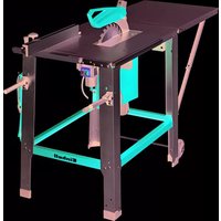
BM 190 - Electric saw EINHELL - Free user manual and instructions
Find the device manual for free BM 190 EINHELL in PDF.

| Product type | Band saw |
| Brand | Einhell |
| Model | BM 190 |
| Voltage | 230 V ~ 50 Hz |
| No-load speed | 1300 rpm |
| Band length | 1524 mm |
| Band speed | 820 m/min |
| Max cutting height (90°) | 85 mm |
| Max cutting height (45°) | 48 mm |
| Spindle-to-frame distance | 190 mm |
| Table dimensions | 290 x 290 mm |
| Table tilt | 0° to 45° |
| Mounted device dimensions | 430 x 305 x 670 mm |
| Weight | Approximately 30 kg |
| Extraction connection diameter | Inner/outer: 40/45 mm |
| Sound pressure level (operation) | 88 dB(A) |
| Sound power level (operation) | 97 dB(A) |
| Safety switch | Undervoltage trip |
| Warranty | 12 months |
| Recommended maintenance | Lubricate bearings every 25-30 h; regular cleaning of chips |
| Required safety equipment | Safety goggles, ear protection, dust mask |
Frequently Asked Questions - BM 190 EINHELL
User questions about BM 190 EINHELL
0 question about this device. Answer the ones you know or ask your own.
Ask a new question about this device
Download the instructions for your Electric saw in PDF format for free! Find your manual BM 190 - EINHELL and take your electronic device back in hand. On this page are published all the documents necessary for the use of your device. BM 190 by EINHELL.
USER MANUAL BM 190 EINHELL
natural_image
Line drawing of a mechanical machine with no visible text or symbolsBM190
/JDD 200
m
GB Please read the operating instructions carefully before assembling and using
©Desdobre as páginas 2-3
D
1. Description (Figure 1/2)
1 Pin guide
The pin guide guides the blade and prevents it from twisting during the sawing operation.
Whenever the blade is changed you have to re-adjust the pins.
2 Fixing screw
The fixing screw is used to fix the upper blade guide in place.
3 Fixing handle for table adjustment
After releasing the fixing handle you can adjust the angle of the table as required.
4 Dial scale for table adjustment
Use the dial scale underneath the table as a reference for quickly setting the approximate angle.
N.B.: To set the exact angle required, carry out a trial cut and make further adjustments as necessary.
5 Knurled screw for setting the blade tension
Use this screw to set the necessary blade tension.
6 Blade adjusting screw
Use this adjusting screw to ensure the blade runs centrally on the blade pulleys.
7 Connection socket for saw dust extractor
Use this socket to connect a saw extraction system or an industrial vacuum cleaner to remove the saw dust and chips.
Internal/external socket diameter: 40/45 mm
8 Switch with undervoltage release
Your bandsaw has a switch with undervoltage release. After a power failure you must reactivate the switch.
Press (I) to switch on.
Press (O) to switch off.
9 Adjustable cross fence
10 Parallel fence
11 Fixing screw for the parallel fence
12 Spring
13 Machine table
2. Items supplied
●Bandsaw
●Machine table
●Parallel fence
●Mitre fence
●Hexagon socket-head wrench
●Standard blade
●Operating instructions
3. Proper use (Figure 3/4)
Assemble the bandsaw as described in Section 7 „Assembly“. Use only those parts supplied. The bandsaw is to be used only to saw squared timber or wood-type workpieces. To cut round materials you have to use suitable holding devices.
The machine is to be used only for its prescribed purpose.
Any use other than that mentioned is considered to be a case of misuse. The user/operator and not the manufacturer shall be liable for any damage or injury resulting such cases of misuse. The machine is to be operated only with suitable saw blades. It is prohibited to use any type of cutting-off wheel.
To use the machine properly you must also observe the safety regulations, the assembly instructions and the operating instructions to be found in this manual.
All persons who use and service the machine have to be acquainted with this manual and must be informed about its potential hazards.
It is also imperative to observe the accident prevention regulations in force in your area.
The same applies for the general rules of occupational health and safety.
The manufacturer shall not be liable for any changes made to the machine nor for any damage resulting from such changes.
Even when the machine is used as prescribed it is still impossible to eliminate certain residual risk factors. The following hazards may arise in connection with the machine's construction and design:
●Damage to hearing if essential ear-muffs are not worn.
●Harmful emissions of wood dust when the machine is used in closed rooms.
●Do not reach into the uncovered cutting area of the blade! Risk of injury to hands!
●Risk of injury when changing the blade! Beware of cutting your fingers etc.
●Risk of injury from catapulted workpieces or parts of workpieces.
●Beware of crushing your fingers.
●Risk of injury from kick-back.
●Beware of the workpiece slipping on a poor support surface.
●Beware of touching the blade.
●Beware of catapulted pieces from branches and workpieces.
GB
The main hazard zones on a woodworking machine are:
●the working area
●the area directly adjacent to any moving parts of the machine
●the kick-back zone
4. I important notes
Please read this manual carefully and pay attention to the information provided. Use this manual to familiarize yourself with the machine, its correct use and safety regulations.
m Safety regulations
●Important: Whenever electric tools are used it is imperative to take basic safety precautions in order to rule out risk of fire, electric shock and injury, e.g.: Follow all these instructions before and while you work with the saw.
●Wear safety gloves whenever you carry out any maintenance work on the blade.
- When cutting with the table tilted, mount the parallel fence to the right of the blade.
- When cutting round wood, use a device to stop the workpiece from twisting (see Figure 1).
- When cutting boards in upright position, use a device to prevent kick-back (see Figure 2).
●A dust extraction system designed for an air velocity of 20 m/s should be connected in order to comply with woodworking dust emission values and to ensure reliable operation.
●In an emergency, switch off the machine directly and pull out the power plug.
- Keep these safety instructions in a safe place.
●Always pull the plug out of the power socket before adjusting or servicing the machine.
●Give these safety regulations to all persons who work on the machine.
●Do not use this saw to cut fire wood.
●Do not use this saw to cross-cut roundwood unless you have a suitable holding device
●The machine is equipped with a safety circuit-breaker to prevent it starting up again after a voltage drop.
●Before you use the machine for the first time, check that the voltage marked on the rating plate is the same as your mains voltage.
- If you need to use an extension cable, make sure its conductor cross-section is big enough for the saw's power consumption. Minimum cross-section: 1mm^2 .
- If you use a cable reel, the complete cable has to be pulled off the reel.
●Do not carry the machine by ist power cable.
- Check the power cable. Never use a faulty or damaged power cable.
●Never remove the plug from the socket-outlet by pulling the cable. Protect the cable from heat, oil and sharp edges.
- Do not leave the saw in the rain and never use it in damp or wet conditions.
●Provide good lighting.
●Never saw near combustible liquids or gases.
●Wear suitable work clothes! Do not wear loose garments or jewellery.
- If you have long hair, wear a hair-net.
●Avoid abnormal postures.
●Operators have to be at least 18 years of age. Trainees of at least 16 years of age are allowed to use the machine under supervision.
- Do not allow other persons, particularly children, to touch the tool or the power cable. Keep them away from your workplace.
- Keep children away from the machine when it is connected to the power supply.
- Keep your workplace clean of wood scrap and any unnecessary objects.
●Persons working on the machine should not be distracted.
●Note the direction of rotation of the motor and saw blade.
●After you have switched off the motor, never slow down the saw blade by applying pressure to its side.
●Fit only blades which are well sharpened and have no cracks or deformations.
●Faulty saw blades have to be replaced immediately.
●Never use saw blades which do not comply with the data specified in this manual.
- It is imperative to make sure that all devices which cover the saw blade are in good working order.
- Never dismantle the machine's safety devices or put them out of operation.
●Damaged or faulty safety devices have to be replaced immediately.
●Never cut workpieces which are too small to hold securely in your hand.
●Never load the machine so much that it cuts out.
●Always press the workpiece firmly against the saw table.
●Never remove loose splinters, chips or jammed pieces of wood when the saw blade is running.
●To rectify faults or remove jammed pieces of wood, always switch off the machine first. - Pull out the power plug! -
●Conversions, adjustments, measurements and cleaning jobs are to be performed only when the motor is switched off. - Pull out the power plug! -
●Before you switch on the machine, check that all wrenches and adjustment tools have been removed.
- When you leave your workplace, switch off the motor and pull out the power plug.
GB
●Electric installation work, repairs and maintenance are to be carried out only by specialists.
●All guards and safety devices have to be refitted immediately after completion of any repairs or maintenance.
- It is imperative to observe the manufacturer's safety, operating and maintenance instructions as well as the dimensions quoted in the technical data.
●It is imperative to observe the accident prevention regulations in force in your area as well as all other generally recognized rules of safety.
●Note the information published by your professional associations (VBG 7j).
●Switch on the dust extraction system each time you use the machine.
●Use the saw only with a suitable vacuum extraction system or a standard industrial vacuum cleaner in order to prevent injuries caused by flying pieces of wood.
I Wear goggles
N Wear ear-muffs
L Wear a breathing mask
Noise emission values
●The saw's noise is measured in accordance with DIN EN ISO 3744; 11/95, DIN EN ISO 11201; 6/96, ISO 7960 Annex J; 2/95. The machine may exceed 85 dB(A) at the workplace. In this case, noise protection measures need to be introduced for the user (ear-muffs).
Cutting Idling
Sound pressure level LPA 88 dB(A) 74 dB(A)
Sound power level LWA 97 dB(A) 83 dB(A)
„The quoted values are emission values and not necessarily reliable workplace values. Although there is a correlation between emission and immission levels it is impossible to draw any certain conclusions as to the need for additional precautions. Factors with a potential influence on the actual immission level at the workplace include the duration of impact, the type of room, and other sources of noise etc., e.g. the number of machines and other neighbouring operations. Reliable workplace values may also vary from country to country. With this information the user should at least be able to make a better assessment of the dangers and risks involved.“
5. Technical data
Voltage: 230 V \~ 50 Hz
Power: 350 W
Idle speed: n0: 1300 rpm
Blade length: 1524 mm
Blade speed: 820 m/min.
Cutting height: 85 mm / 90°
48 mm / 45°
Throat: 190 mm
Table size: 290 x 290 mm
Tilting range of table: 0° to 45°
Dimensions when assembled: 430 x 305 x 670 mm
6. Before starting (Figure 1)
●Make sure the machine stands securely, i.e. bolt it to a workbench or solid base. There are two holes for this purpose in the machine foot.
●All the covers and safety devices have to be properly fitted before the machine is switched on.
- It must be possible for the saw blade to run freely.
- When working with wood that has been processed before, watch out for foreign bodies such as nails or screws etc.
- Before you actuate the On/Off switch, make sure that the saw blade is correctly fitted and that the machine's moving parts run smoothly.
●Before you connect the machine to the power supply, make sure the data on the rating plate is the same as that for your mains.
GB
Definition of terms
Kerf
The gap formed when material is removed by the moving blade.
Cutting line
The line along which the blade cuts through the workpiece.
Saw set
A saw blade's teeth are alternately set slightly outward in order to prevent the blade jamming in the kerf. The kerf is therefore wider than the blade thickness.
Workpiece
The object being cut. The surfaces of a workpiece are usually referred to as the top, bottom, front edge and rear.
Longitudinal cutting
Sawing along the grain of the wood.
Angle cutting
Cutting at an angle to the surface of the workpiece that is not a right angle.
Mitre cutting
Cutting at an angle to the front edge of the workpiece that is not a right angle.
Double mitre cutting
A combination of angle and mitre cutting.
The bandsaw must only ever be operated from the front or side.
Be sure not to install or operate the bandsaw in damp or wet conditions.
7. Assembly (Figure 1/2)
Caution! Pull out the power plug before carrying out any maintenance or resetting work on the bandsaw!
The bandsaw is preassembled at the factory. All you have to do is fasten the machine table (13) to the machine stand with the quick-release clamping screw. Ideally you should bolt the bandsaw to a solid worktop or workbench using the holes provided in the machine foot. Check the data on the rating plate. Voltage and frequency have to comply.
7.1 Adjusting the cutting height
The upper blade guide has to be adjusted in accordance with the thickness of the workpiece. Undo the fixing screw (2) and adjust the blade guide so it is approx. 2-3 mm higher than the thickness of the workpiece you want to saw. Re-tighten the fixing screw. Check the setting before every cut and re-adjust if necessary.
7.2 Changing the blade
Caution! Pull out the power plug before changing the blade.
The blade is sharp! Beware of cutting yourself! Wear safety gloves when carrying out any work on and with the blade.
- Undo the fixing screw (2) and move the upper blade guide unit to a position approx. half way between the table and the frame.
- Release the two machine frame locks and open the housing cover.
- Undo the two fastening screws of the blade guard and remove the guard.
- Remove the table adjusting screw, washer and thumb nut from the bandsaw table.
- Move the blade through the slot in the table as far as the middle of the table, making sure that the teeth face the front edge of the table and the tips of the teeth point down.
- Remove all tension from the blade by turning the tension button down.
- Now place the blade on the two blade pulleys and align centrally on the pulley tyres (the rubber surface on the pulleys).
Important!
Remove the tension from the blade if you are not going to use the bandsaw for a while. Place a notice to this effect on the machine where it cannot be overlooked. Be sure to re-tension the blade before you re-start the machine.
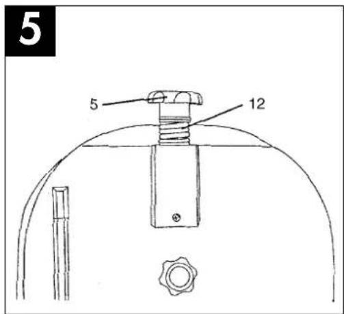
7.3 Tensioning the blade (Figure 5)
Caution!
Make sure the blade is tensioned before you switch on the machine. The blade tensioning device has to be locked.
Important!
The blade may break if the tension is too high. Beware of injury!
If the tension is too low, the powered blade
GB
pulley will spin while the blade does not move.
-
Turn the knurled screw (5) anticlockwise until the spring (12) is under no tension. » Starting position!
-
Turn the knurled screw (5) clockwise until the spring begins to tension.
-
Leave the knurled screw (5) in this position and see Point 4.
-
Setting the blade tension on blades of various thicknesses:
1/8" blade: Point 2 setting plus 1 complete turn
1/4" blade: Point 2 setting plus 2 complete turns
3/8" blade: Point 2 setting plus 2 complete turns
7.4 Adjusting the blade (Figure 5)
The blade tension has to be set correctly before you can adjust the blade.
- Slowly turn the upper blade pulley clockwise by hand. The blade should run in the middle of the pulley tyre. If it does not you will have to adjust the tilt of the upper blade pulley.
-
The knurled screw (6) for adjusting the blade run is situated at the back of the machine frame in the middle. Use this screw to adjust the run. Keep the side cover open while making the adjustment. Turn the guide pulleys by hand to check the run. Remember that the blade runs from top to bottom.
-
If the blade tends to run to the back, turn the screw (6) clockwise while turning the blade pulley by hand until the blade runs in the middle.
-
Now check the blade run on the lower blade pulley. The full width of the blade should rest on the pulley tyre. Check that the position of the upper blade pulley runs centrally.
-
Before you switch on the machine, turn the upper blade pulley vigorously several turns by hand to see whether the blade runs off the pulleys. If it does, you must re-adjust the upper blade pulley.
7.5 Adjusting the blade guide
Adjust the upper and lower blade guide after you have adjusted and checked the blade tension. The guide pins of the upper and lower blade guides have to be set to leave a gap of a maximum 1 mm to the right and left of the blade. Adjust the support bearing so that the back edge of the blade runs on the outer ring of the bearing. The support bearing is designed to support the blade on deep cuts in order to guarantee perfect cutting.
Important!
The blade will be rendered useless if its teeth touch the guide pins while the blade is running. Correct adjustment of the upper and lower blade guide is vital, therefore, if your blade is to serve you for a long time.
7.6 Upper blade guard
Adjust the blade guard to leave a gap of a maximum 5 mm between the workpiece and the guard. As a general rule, keep the gap as small as possible.
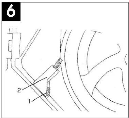
7.7 Brake system (Figure 6)
The bandsaw's brake system needs regular attention. The bandsaw brake takes the form of a wheel brush which is situated inside the housing cover. Please contact your dealer when the wheel brush is worn. Check the wheel brush in regular intervals before starting the machine. To adjust the brake:
- Undo the screw (1) and move the brush (2) to the correct position.
- Re-tighten the screw (1).
7.8 Cross fence
The cross fence is designed to guide the workpiece safely when making cross cuts or mitre cuts. The cross fence has a 45^ dial scale on both sides for mire cutting.
7.9 Parallel fence
The workpiece is guided along the parallel fence to make straight longitudinal cuts. The parallel fence can be adjusted to the required cutting width.
8. Operation
For all cutting operations it is important to position the blade guide as close as possible to the workpiece.
This will ensure safe operation as well as cuts of optimum quality.
Always guide the workpiece with both hands, holding it flat on the table in order to prevent the blade from jamming. Feed the workpiece at a speed that enables the blade to cut through the material without difficulty.
Always use the parallel fence or the cross fence on all cuts for which they are intended. This will prevent the blade from leaving the cutting line, particularly
GB
when working with a tilted table.
Plan your work steps in advance. Follow the old rule: "It's better to measure twice and cut once than to measure once and cut twice!" Always aim at making a complete cut in one pass rather than in a stop-and-go operation requiring the workpiece to be withdrawn. If you have to withdraw the workpiece, switch off the bandsaw first and wait for the blade to stop before freeing the workpiece. Remember that the blade produces a kerf. Adjust the cutting width accordingly so that the kerf lies in the off-cut section of the workpiece.
After every new adjustment we recommend you to make a trial cut in order to check the new settings.
8.1 Longitudinal cuts
Longitudinal cutting is when you use the saw to cut along the grain of the wood.
It is possible to make freehanded cuts along a marked line. You will achieve better results, however, if you guide the workpiece along the parallel fence. For right-angled cuts (with the table at right angles to the blade), place the parallel fence to the left of the blade so that you can guide the workpiece safely along the fence with your right hand. For mitre cuts with the table tilted, place the parallel fence to the right of the blade on the downward pointing side (provided the workpiece is wide enough) in order to stop the workpiece from slipping off.
8.2 Cross cuts
Cross cutting is when you use the saw to cut at right angles to the grain of the wood. It is also possible to make freehanded cross cuts. We recommend using the cross fence, however, in the interest of safety as well as precision. The cross fence can be adjusted to angles of up to 45^ for mitre cuts. With the table tilted it is also possible to make double mitre cuts.
Hold the workpiece securely against the cross fence and flat on the table. Watch your fingers, particularly toward the end of the cut. Keep away from the blade. Small workpieces should be held by a screw clamp. The cross fence can be equipped with a limit stop to enable several workpieces to be cut exactly to the same length. You can also use this limit stop as a support when working with the table tilted.
8.3 Freehanded cuts
One of the most outstanding features of a bandsaw is the ease with which it allows you to make curved
cuts. Freehanded cuts should be made at low feed speed so that you can guide the blade along the required line. Be careful not to push the workpiece sideways off the cutting line or the blade will twist and jam in the kerf. It often pays to first cut off surplus material up to about 10 mm from the cutting line. In the case of radii which are too tight for the blade to cut correctly, it can help to make a series of close-lying cuts at right angles to the curved line. When you saw the radius the material will drop off and the blade cannot become jammed.
9. Cleaning and maintenance
Bearings
Apply high-quality machine grease to the bearings of the guide pulleys at regular intervals but at least after every 25-30 hours in operation.
Cleaning
Remove saw dust and chips regularly from the inside of the bandsaw. Switch off the machine and pull out the power plug before you open the housing cover. When the cover is open, clean the inside with a brush or vacuum cleaner. After every work session, remove the dust and chips from the cooling vents of the motor.
Maintenance
Do not carry out any repairs yourself. If any problems arise, take your bandsaw to a specialist workshop.
10. Ordering replacement parts
Please provide the following information on all orders for replacement parts:
- Type of machine
- Article number of the machine
- ID number of the machine
- Replacement part number of the part you require
11. Troubleshooting
Caution!
For your own safety, always set the switch to OFF and pull the power plug out of the socket-outlet before you carry out any maintenance work.
Fault:
Blades break
Possible cause:
- Wrong tension
- Overloading
- Wrong blade
- Warped blade
Remedy:
Re 1: Correct the blade tension
Re 2: Lower the feed speed
Re 3: Use narrow blades for thin material and wide blades for thicker material
Re 4: Do not apply any pressure to the side of the blade
Fault:
Motor does not run
Possible cause:
- Line fuse blown
- Plug or power cable defective
- Motor defective
Remedy:
Re 1: Check the fuse
Re 2: Replace the defective parts
Re 3: Contact your dealer. Every attempt to repair the machine yourself entails a certain risk. Have repairs carried out only by an authorized workshop.
Fault:
Vibration: Vibrations are owed to the technology used and cannot be prevented completely.
Possible cause:
- Bandsaw loosely mounted on the workbench or base
- Uneven mounting surface
-
Bandsaw table not tightened or lies against the motor
-
Motor fastening screws loose
Remedy:
Re 1: See Section 6 „Before starting“
Re 2: The greater the dead weight of the base or workbench, the smaller the vibration. A workbench made of solid wood is to be preferred to a plywood design.
Re 3: Tighten the table fixing button; check the table position
Re 4: Tighten the screws
Fault:
Blade runs off the cutting line
Possible cause:
Blade guides wrongly adjusted
Remedy:
Adjust the blade guide as described in Section 7.5 „Adjusting the blade guide“.
F
1. Description de la machine (fig. 1/2)
1. Guidance à tige
Puissance: 350 watts
The guarantee period begins on the sales date and is valid for 1 year.
Responsibility is assumed for faulty construction or material or functional defects.
Any necessary replacement parts an necessary repair work are free of charge.
We do not assume responsibility for consequential damage.
Your customer service partner
© GARANTIE EINHELL
⑤ EINHELL GARANTIBEVIS
© EINHELL-GARANTIDOKUMENT
DK EINHELL GARANTIBEVIS
32, Craven Court, Winwick Quay,
Warrington, Cheshire WA2 8QU
F Agence Commerciale Kettering
DK Danish Trading Co. Silkeborg ApS
Rodelundvej 11 - Rodelund
DK-8653 Them
Technical changes subject to change