BM 240 - Electric saw EINHELL - Free user manual and instructions
Find the device manual for free BM 240 EINHELL in PDF.


| Product type | Electric band saw |
| Brand | Einhell |
| Model | BM 240 |
| Power | 300 W |
| Mains voltage | 230 V ~ 50 Hz |
| No-load speed | 890 rpm |
| Band speed | 672 m/min |
| Band length | 1520 mm |
| Band width (max.) | 10 mm |
| Cutting height at 90° | 75 mm |
| Cutting height at 45° | 45 mm |
| Throat depth | 230 mm |
| Table dimensions | 290 x 290 mm |
| Table tilt | 0° to 45° |
| Max. workpiece dimensions | 1500 x 1000 mm |
| Weight | 13.2 kg |
| Sound pressure level LPA (operating) | 92.5 dB(A) |
| Sound power level LWA (operating) | 105.5 dB(A) |
| Safety switch (undervoltage) | Yes |
| Dust extraction connection | Yes (adapter included) |
| Parallel stop | Yes |
| Cross stop | Yes |
| Warranty | 2 years |
Frequently Asked Questions - BM 240 EINHELL
User questions about BM 240 EINHELL
0 question about this device. Answer the ones you know or ask your own.
Ask a new question about this device
Download the instructions for your Electric saw in PDF format for free! Find your manual BM 240 - EINHELL and take your electronic device back in hand. On this page are published all the documents necessary for the use of your device. BM 240 by EINHELL.
USER MANUAL BM 240 EINHELL

3
natural_image
Close-up of a mechanical component being handled, labeled with numbers 16, 18, and 3 (no readable text or symbols beyond labels)
natural_image
Mechanical component diagram showing a curved bracket with labeled parts (16 and 18), no readable text or symbols beyond labels

natural_image
Close-up of a sewing machine needle stitching metal sheets, with a hand adjusting the component (no visible text or symbols)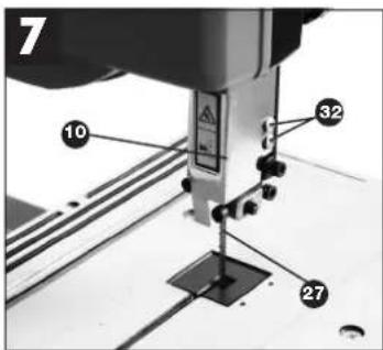


natural_image
Close-up of a 3D printer cutting a wooden block, no visible text or symbols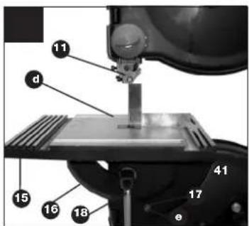


5




natural_image
Close-up of a hand operating a sewing machine with a wooden base (no visible text or symbols)
natural_image
Close-up of a hand using a sewing machine to press or install electronic components (no visible text or symbols)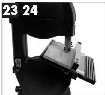
natural_image
Close-up of a black mechanical device with a metallic bracket and attached clamped components (no visible text or symbols)
natural_image
Close-up of a hand inserting a device into a black device (no visible text or symbols)
natural_image
Close-up of a mechanical testing machine with a wooden block mounted on its side (no visible text or symbols)-
On/Off switch
-
Extractor adapter
-
Retaining screw
-
Wing nut
-
Machine foot
-
Extractor socket
-
Lower blade pulley
-
Upper blade pulley
-
Tightening screw
-
Blade guai
-
Upper blade guide
-
Side cover
-
Toggle fastener
-
Cross stop
-
Machine table
-
Dial scale for tilt angle
-
Arrow
-
Fixing handle for table
-
Setting wheel for blade guide
-
Fixing handle for blade guide
-
Clip for parallel stop
-
Setting screw for upper blade pulley
-
Motor
-
Parallel stop
-
Machine frame
-
Blade
2. Items supplied
- Bandsaw
● Machine table
● Cross stop
- Parallel stop
3. Proper use
The BM 240 bandsaw is designed to perform longitudinal and cross cuts on timber or wood-type materials. To cut round materials you must use suitable holding devices. The machine is to be used only for its prescribed purpose.
Any use beyond that mentioned is considered to be a case of misuse. The user/operator and not the manufacturer shall be liable for any damage or injury resulting from such cases of misuse.
The machine is to be operated only with suitable saw blades. To use the machine properly you must also observe the safety regulations, the assembly instructions and the operating instructions to be
found in this manual.
All persons who use and service the machine have to be acquainted with this manual and must be
informed about the machine's potential hazards.
It is also imperative to observe the accident
prevention regulations in force in your area.
The same applies for the general occupational health and safety.
The manufacturer shall not be liable for any changes made to the machine nor for any damage resulting from such changes.
Even when the machine is used as prescribed it is still impossible to eliminate certain residual risk factors. The following hazards may arise in connection with the machine's construction and design:
● Damage to hearing if ear-muffs are not used as necessary.
● Harmful emissions of wood dust when used in closed rooms.
- Contact with the blade in the uncovered cutting zone.
● Injuries (cuts) when changing the blade.
● Injury from catapulted workpieces or parts of workpieces.
● Crushed fingers.
- Kickt
- Tilting of the workpiece due to inadequate support.
● Touching the blade.
● Catapulting of pieces of timber and workpieces.
4. Important notes
Safety information
IMPORTANT! Whenever you use electric tools it is imperative to take basic safety precautions in order to reduce the risk of fire, electric shock and personal injury. Essential safety precautions include:
- Keep your work area tidy!
- An untidy work area invites accidents.
- Check the working conditions!
- Do not expose electric tools to rain.
- Never use electric tools in damp or wet locations. - Make sure there is good lighting.
- Do not use electric tools near flammable liquids or gases.
- Guard against electric shock!
- Avoid body contact with earthed components.
- Keep other persons away!
- Do not allow other persons, particularly children, to touch the tool or cable. Keep all persons out of your work area.
- Store tools in a safe place!
- When tools are not in use they should be stored in a dry, locked room out of children's reach.
- Do not overload your tools!
- Tools work better and safer when used within their quoted capacity range.
- Use the right tool!
- Never use tools or attachments with insufficient power for the job in hand.
- Never use tools on jobs for which they were not intended. For example, do not use a hand-held circular saw to cut down trees or lop off branches.
- Wear suitable work clothes!
- Do not wear loose clothing or jewelry as they may get caught in moving parts.
- Non-slip shoes are recommended when working outdoors.
- Wear a hair net if you have long hair.
- Use personal safety equipment!
- Wear safety goggles
- Use a dust mask when working on dusty jobs
- Connect up a vacuum extraction system!
- If there are provisions for connecting up a vacuum extraction system, make sure that such a system is fitted and in use.
- Do not mis-use the cable!
Do not carry the tool by its cable or pull on the cable to remove the plug from the socket-outlet. Protect the cable from heat, oil and sharp edges.
- Secure your workpiece!
- Use clamps or a vise to hold the workpiece securely. This is safer than using your hand and will enable you to operate the machine with both hands.
- Avoid abnormal working postures!
- Make sure you stand squarely and keep your balance at all times.
- Look after your tools!
- Keep your tools sharp and clean for better and safer performance.
- Follow the instructions for maintenance work and for changing any attachments.
- Check the plug and cable regularly and, if damaged, have them replaced by an authorized specialist.
- Check the extension cable regularly and replace it if damaged.
- Keep handles dry and free from oil and grease.
- Always pull out the power plug:
- When the tool is not being used, before carrying out any maintenance work and when changing attachments such as blades, bits and cutters of any kind.
- Remove adjusting keys and wrenches!
- Make sure that all keys and adjusting wrenches are removed from the tool before switching it on.
- Avoid unintentional starting!
- Make sure that the switch is in OFF position when inserting the power plug.
- When using an extension cable outdoors:
- Check that it is approved for outdoor duty and is marked accordingly.
- Be alert at all times!
- Watch what you are doing. Use common sense. Do not operate the tool if your mind is not on your work.
- Check the tool for damage!
- Each time before re-using the tool, carefully check that the guards or any slightly damaged parts are working as intended.
- Check that the moving parts are in good working order, that they do not jam, and that no parts are damaged. Make sure that all parts are fitted correctly and that all other operating conditions are properly fulfilled.
- Unless otherwise stated in the operating instructions, damaged guards and parts have to be repaired or replaced by an authorized service center.
- Have damaged switches replaced by a customer service workshop.
- Never use any tool if its switch cannot be turned off and on.
21. IMPORTANT!
- The use of any accessory or attachment other than those recommended may involve a risk of injury for you personally.
- Have repairs carried out only by a qualified electrician!
- This electric tool complies with the pertinent safety regulations. Repairs are to be carried out only by a qualified electrician using original replacement parts or the user may suffer an accident.
-
Wear safety gloves whenever you carry out any maintenance work on the blade!
-
When cutting with the table tilted, mount the parallel stop to the right of the blade.
-
When cutting round wood, use a device to stop the workpiece from twisting.
-
When cutting boards in upright position, use a device to prevent kick-back.
-
A dust extraction system designed for an air velocity of 20 m/s should be connected in order to comply with woodworking dust emission values and to ensure reliable operation.
-
Give these safety regulations to all persons who work on the machine.
-
Do not use this saw to cut fire wood.
-
The machine is equipped with a safety switch to prevent it being switched on again accidentally after a power failure.

GB
- Before you use the machine for the first time, check that the voltage marked on the rating plate is the same as your mains voltage.
- If you use a cable reel, the complete cable has to be pulled off the reel.
- Persons working on the machine should not be distracted.
- Note the direction of rotation of the motor and blade.
- Never dismantle the machine's safety devices or put them out of operation.
- Never cut workpieces which are too small to hold securely in your hand.
- Never remove loose splinters, chips or jammed pieces of wood when the saw blade is running.
- It is imperative to observe the accident prevention regulations in force in your area as well as all other generally recognized rules of safety.
- Note the information published by your professional associations.
- Position the blade guard so it is approx. 3 mm above the material you want to saw.
- Important! Support long workpieces (e.g. with a roller table) to prevent them sagging at the end of a cut.
- Make sure the blade guard (10) is in its lower position when the saw is being transported.
- Safety guards are not to be used to move or misuse the machine.

Wear safety goggles

Wear ear-muffs

Wear a breathing mask
- Technical data
| Voltage: 230V~50 Hz |
| Power: 300 W |
| Ideal speed no: 890 min |
| Blade length: 1520 mm |
| Max. blade width: 10 mm |
| Blade speed: 672 m/min |
| Cutting height: 75 mm / 90° |
| 45 mm / 45° |
| Throat: 230 mm |
| Table size: 290 x 290 mm |
| Tilting range of table: 0" to 45° |
| Workpiece size: 1500 x 1000 mm |
| Weight: 13.2 kg |
Noise emission values
Cutting Idling
| Sound pressure level LPA | 92.5 dB (A) | 88.7 dB (A) |
| Sound power level LWA | 105.5 dB (A) | 101.7 dB (A) |
6. Before putting the machine into operation
● Make sure the machine stands securely, i.e. bolt it to a workbench or solid base. There are two holes for this purpose in the machine foot.
● All covers and safety devices have to be properly fitted before the machine is switched on.
● It must be possible for the blade to run freely.
- When working with wood that has been processed before, watch out for foreign bodies such as nails or screws etc.
- Before you actuate the On/Off switch, make sure that the saw blade is correctly fitted and that the machine's moving parts run smoothly.
- Before you connect the machine to the power supply, make sure the data on the rating plate is the same as that for your mains.
7. Assembly
CAUTION!
Pull out the power plug before carrying out any maintenance, resetting or assembly work on the bandsaw!
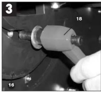
7.1. Fitting the machine table (Figures 3 - 5)
● Undo the fixing handle (18)
- Remove the retaining screw (3).
- Place the machine table (15) on the machine frame (25) from the right. Please note that the blade (26) is positioned in the center of the table.
● The dial scale (16) of the table (15) must be fitted in the guide (on the machine frame (25))
● Screw on the locking grip (18) again to clamp the saw table (15) in place.
- Insert the retaining screw (3) and tighten. Please note that the wing nut (4) of the retaining screw (3) is located on the underside of the table.
7.2. Tensioning the blade (Figure 6)
- CAUTION! Remove the tension from the blade if the bandsaw is not going to be used for some time. Be sure to re-tension the blade before you start the machine.
● Turn the tightening screw (9) for tensioning the blade (26) in a clockwise direction.
● The correct blade tension can be checked by applying pressure to the side of the blade with your finger, somewhere in the middle between the two blade pulleys (7 + 8). You should only be able to bend the blade (26) very slightly (approx. 1-2 mm). - IMPORTANT! The blade may break if the tension is too high. BEWARE OF INJURY! If the tension is too low, the powered blade pulley (7) will spin while the blade does not move.
7.3 Adjusting the blade
- CAUTION! The blade tension has to be set correctly before you can adjust the blade.
● Undo the toggle fasteners (13) and open the left side cover (12). - Slowly turn the upper blade pulley (8) clockwise by hand. The blade (26) should run in the middle of the pulley. If it does not, you will have to adjust the tilt of the upper blade pulley (8).
- If the blade (26) tends to run to the back of the blade pulley (8), i.e. towards the machine frame (25), turn the setting screw (22) anti-clockwise while turning the blade pulley (8) by hand until the blade (26) runs in the middle.
- If the blade (26) tends to run to the front edge of the blade pulley (8), turn the setting screw (22) in a clockwise direction.
● After setting the upper blade pulley (8) you need to check the blade (26) position on the lower blade pulley (7). The blade (26) should run in the
middle of the blade pulley (7), as above. If it does not, you will have to adjust the tilt of the upper blade pulley (8) again.
● Turn the upper blade pulley several times until the adjustment to the upper blade pulley (8) has an effect on the blade position of the lower blade pulley (7).
- Close the side cover (12) when you have finished adjusting the blade and fasten with the Allen screws (13).
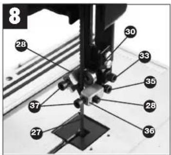
7.4. Adjusting the blade guide (Figures 7 - 10)
Whenever you change the blade you must reset both the support bearings (30 + 31) and the guide pins (28 + 29).
● Undo the toggle fastener (13) to open the left side cover (12).
● Undo the Allen screws (32) and remove the blade guard (10).
7.4.1. Upper support bearing (30)
● Undo the Allen screw (33).
- Move the support bearing (30) so that it is almost touching the blade (26). There should be a gap of approx. 0.5 mm.
● Re-tighten the Allen screws (33).
7.4.2. Adjusting the lower support bearing (31)
- Adjust in the same way that the upper support bearing was adjusted.
The blade (26) is only supported by the support bearings (30 + 31) during cutting. When idle the blade should not touch the ball bearings.
7.4.3. Adjusting the upper guide pins (28)
● Undo the Allen screw (35)
- Move the mount (36) of the guide pins (28) so that there is a gap of approx. 1 mm between the front edge of the guide pins (28) and the gullet of the blade in front.
● Re-tighten the Allen screw (35)
- CAUTION! The blade will be rendered useless if the teeth touch the guide pins while the blade is running.
● Undo the Allen screws (37).
- Move the guide pins (28) towards the blade so that there is a gap of approx. 0.5 mm between the guide pins (28) and the blade (26). The blade
GB
must not jam.
● Re-tighten the Allen screws (37).
● Turn the upper blade pulley (8) several times in a clockwise direction.
- Check the setting of the guide pins (28) again and re-adjust if necessary.
7.4.4. Adjusting the lower guide pins (29)
● Undo the Allen screw (40).
- Move the mount (49) of the guide pins (29) so that there is a gap of approx. 1 mm between the front edge of the guide pins (29) and the gullet of the blade in front.
● Re-tighten the Allen screw (40)
- CAUTION! The blade will be rendered useless if the teeth touch the guide pins while the blade is running.
● Re-tighten the Allen screws (38).
- Move the guide pins (29) towards the blade so that there is a gap of approx. 0.5 mm between the guide pins (29) and the blade (26). The blade must not jam.
● Re-tighten the Allen screws (38).
● Turn the lower blade pulley (7) several times in a clockwise direction.
- Check the setting of the guide pins (29) again and re-adjust if necessary.
IMPORTANT! After completing the above adjustments, the upper (10) and lower (34) blade guards must be refitted.
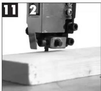
7.5. Adjusting the upper blade guide (11) (Figure 11)
● Undo the fixing handle (20).
● Turn the setting wheel (19) to lower the blade guide (11) as close as possible to the workpiece to be cut. The gap should be approx. 2-3 mm.
● Re-tighten the fixing handle (20).
- Check the setting before each cut and re-adjust if necessary.
7.6. Adjusting the machine table (15) to 90° (12/13)
● Move the upper blade guide (11) to the top.
● Undo the fixing handle (18).
- Set the angle between the blade (26) and the table (15).
- Turn the setting wheel (19) to tilt the saw table (15) until it is at an angle of exactly 90^ to the blade (26).
● Re-tighten the fixing handle (18).
- Undo the nut (42).
- Adjust the Allen screw (41) until there is contact
20
with the machine frame (26).
● Re-tighten the nut (42) to fasten the Allen screw (41).
- Undo the recessed head screw (e) to position the arrow (17) on the 0^ mark on the dial scale (16)
7.7. Blade selection
The blade supplied with the bandsaw is designed for all-purpose use. When you select a blade you should have regard to the following criteria:
- Use a narrow blade to cut tighter radii than you can with a wider blade.
- Wide blades are used to saw straight cuts. This is particularly important in cutting wood because the blade has a tendency to follow the grain of the wood and thereby deviate easily from the cutting line.
● Finely toothed blades provide smoother cuts but are slower than coarse blades.
Important: Never use warped or lacerated blades!
7.8. Changing the blade (Figure 14)
- Move the blade guide (11) into a position approximately half way between the table (15) and the machine frame (25).
- Undo the toggle fastener (13) and open the side cover (12).
● Undo the two Allen screws (32) and remove the blade guard (10) (see Figure 7).
● Unscrew and remove the wing nut (4) and retaining screw (3) (see Figure 5).
● Turn the tightening screw (9) anti-clockwise to remove the tension from the blade (26). - Remove the blade (26) from the blade pulleys (7,8) and take out through the slot in the table (15).
● Fit the new blade (26), aligned centrally on the blade pulleys (7,8). The teeth of the blade (26) must point down towards the table.
down towards the table. ● Tension the blade (26) (see 7.2) - Pension the blade (20) (see 7.2)
- Replace the blade guard (10) and close the side cover (12).
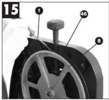
7.9. Changing the rubber tires on the blade pulleys (Figure 15)
After a certain time the rubber tires (46) on the blade pulleys (7/8) will get worn by the sharp teeth of the blades and must be replaced.
● Open the side cover (12).

- Remove the blade (26) (see 7.7).
● Lift the edge of the tire (46) with a small screwdriver (f) and remove from the blade pulley (8).
● Repeat for the lower blade pulley (7).
● Fit the new tire (46), replace the blade (26) and close the side cover (12).
7.10. Changing the table insert (Figure 16)
To prevent increased likelihood of injury the table insert (44) should be changed whenever it is worn or damaged.
● Detach the lable (15) (see 7.1).
● Lift out the worn table insert (44).
● Fit the replacement table insert by following the above in reverse.
7.11. Extractor sockets
The bandsaw is equipped with extractor sockets (19) for extracting sawdust and chips.
Using the extractor adapter (3) included in delivery, connection to a range of different sawdust extractors is straightforward.
8. Control elements
8.1. On/Off switch (Figure 17)
● To turn the machine on, press the green button "1" (g).
- To turn the machine off again, press the red button „0“ (h).
- Your bandsaw has a switch with undervoltage release. After a power failure you must reactivate the switch.
8.2. Parallel stop (Figure 18)
● Push the clip (21) on the parallel stop (24) upwards.
- Move the parallel stop (24) along the table (15), from either the right or left of the blade (26), and position as required.
- Push the clip (21) down to fix the parallel stop (24). If the clip (21) does not give enough hold, turn it clockwise several times until the parallel stop is securely fixed.
● You must always ensure that the parallel stop (24) is positioned parallel to the blade (26).
8.3. Cross stop (Figure 19)
- Slide the cross stop (14) into the groove (i or j) of the table (15).
● Undo the knurled screw (47).
● Turn the cross stop (14) until the arrow (48) points to the angle required (k).
● Re-tighten the knurled screw.
8.4. Angle cuts (Figure 20)
To enable you to perform angle cuts parallel to the blade (26), the table (15) can be tilted forwards between 0^ - 45^ .
● Undo the fixing handle (18).
- Tilt the saw table (15) forward until the pointer (17) coincides with the required angle value on the man scale (16).
● Re-tighten the fixing handle (18).
- Important: When the table (15) is tilted, place the parallel stop (24) to the right of the blade (26) on the downward pointing side (provided the workpiece is wide enough) in order to stop the workpiece from slipping off.
9.0. Operation
Caution! After every new adjustment we recommend you to make a trial cut in order to check the new settings.
● For all cutting operations it is important to position the blade guide (11) as close as possible to the workpiece (see 7.5).
● Always guide the workpiece with both hands, holding it flat on the table (15) in order to prevent the blade (26) from jamming.
● Feed the workpiece at a uniform speed that enables the blade to cut through the material without difficulty and without blocking.
● Always use the parallel stop (24) or the cross stop (14) on all cuts for which they are intended.
● Always aim at making a complete cut in one pass rather than in a stop-and-go operation requiring the workpiece to be withdrawn. If you have to withdraw the workpiece, switch off the bandsaw first and wait for the blade (26) to stop before freeing the workpiece.
● The workpiece must always be guided by the longer side during cutting.
9.1. Longitudinal cuts (Figure 21)
Longitudinal cutting is when you use the saw to cut along the grain of the wood.
● Place the parallel stop (24) to the left of the blade

GB
(25), as far as possible, for the width required.
● Lower the blade guide (11) down to the workpiece (see 7.5).
● Switch on the saw.
- Press the edge of the workpiece with your right hand to hold it securely against the parallel stop (24) and flat on the table (15).
● Guide the workpiece along the parallel stop (24) and through the blade (26) at a uniform speed.
9.2. Cross cuts (Figure 22)
- Slide the cross stop (14) into one of the grooves in the table (15) and adjust to the required angle (see 8.3).
● Lower the blade guard (10) to the workpiece (see 7.5).
● Switch on the saw.
● Hold the workpiece securely against the cross stop (14) and the table (15) and guide it at a uniform speed through the blade (26).
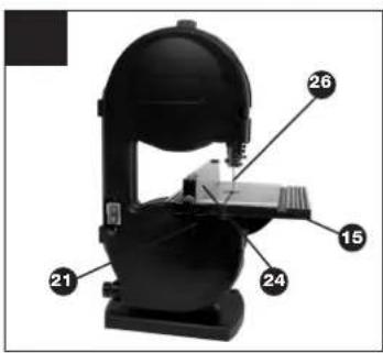
9.3. Angle cuts and double miter cuts (Figure (23/24))
9.4. Freehanded cuts (Figure 25)
One of the most outstanding features of a bandsaw is the ease with which it allows you to make curved cuts and radii.
● Lower the blade guide (11) to the workpiece (see 7.5).
● Switch on the saw.
● Hold the workpiece securely on the table (15) and guide slowly through the blade (27).
● Freehanded cuts should be made at low feed speed so that you can guide the blade (27) along the required line.
- It often pays to first cut off surplus curves and corners up to about 6 mm from the cutting line.
- In the case of curves which are too tight for the blade to cut correctly, it can help to make a series of close-lying cuts at right angles to the curved line. When you saw the radius the material will simply drop off.
10. Maintenance
● Caution! Pull out the power plug first.
- Remove dust and dirt regularly from the bandsaw. Cleaning is best carried out with a fine brush or a cloth.
22
- Do not use caustic cleaning agents for cleaning plastic.
11. Ordering replacement parts
Please provide the following information on all orders for replacement parts:
● Type of machine
● Article number of the machine
● ID number of the machine
● Replacement part number of the part you require (Please refer to the list of replacement parts).

- Cumpra as normas de manutenção e as
EC Declaration of Conformity
E Déclaration de Conformité CE
NL EC Conformiteitsverkiering
E Declaración CE de Conformidad
P Declaração de conformidade CE
⑤ EC Konformitetaförklaring
EC Yhdenmukaisuusilmoitus
EC Konflonitätserklæring
EC Заявление о конформности
Dichiarazione di conformità CE
RQ Declaratie de conformitate CE
18 AT Uygunluk Deklarasyonu
©EC Δήλωση περι της ανταπόκριος
① Dichiarazione di conformità CE
OK EC Overensstemmelseserklaring
EU prohláseni o konformite
H EU Konformkijelentes
EU Izjava o skladnosti
PL Oświadczenie o zgodności z normami
Europejskiej Wspolnoły
UK Vyhásenie EU o konformite

BM 240
Der Überzeichnende erhiert in Namen der Firma die Über- veränstmehrung des Produktions.
The undersigned declares in the name of the company that the product is in compliance with the following guidelines and standards.
Le sousigné déciate au nom de l'entreprise le dûnfumée du produit avec les directives et nonmes suivantes.
De cedafiekbaar verkunt in nam van de firma dat het product overeenstem met de volgende richtigen en normen. El abajo termene destara en el nombre de la empresa, a conformidad del producto con las direcciones y normas squalies.
O significave declara em nome da hina a conformidade do
praxivo com as seguintes direcivos e normas
Onderlödennad förkacar i ärmane nastro att produkten överensaktammer: mod fögande direktov och standarder.
Stekrjollarsi drnoilasa lukkeen näigast, että tuole vastas seumäia dielstinenja ja standardnej:
Underbegnade erfasser på vegne av finriser i produkter
solvavens med forgende direklaver og normer.
Подписицион подтверждает от имени фирсию что частявшей ущилке, редствит, кур в требованиям. Предующие «филгивных документов.
Az azúro kivelenti, a ofg náveben, a termák megegyezését a követékeo, tányvonyakási és normálkuat.
Subsammatul declară în aunale finană că produsul core-
Imzalayan keyi, Bema adina ürünin esagida erilim yonetimo-
oklere ve domara uygun tokuagunu beyan eder.
Публика тол. пројодос, тюс, тоус, окоаюбую
« sottoscillo dichiana » nome della città la conformità de
progetto con le direttive e la norme sequenti.
På timaets vagra erklare' underlegnede, af productet modelkommer kavens i folande dreidver og normer.
Něs odképrášky jmenomí čímny pruhlasuje, že výtobek odpo- vídů návouční měnětvom a normán
Az azaro Kjelzó, a cág herviári a kettők megagyzában a
xionékiartú irányonalákkai és normakul
Podstani zotrijami v menu podredja, 328 je priznad v sodnju- nis v sejedni smarnučen v standari.
Nobel podprisomy obiadona w artieniu firmy, ze ovoja je st. opstovu z Čančenjučkymi 600-2000/1000/1000
Povosušća zavatne prablasuje v mana litn, pe hoža včetocja v v sildaci o odločovljeni stvenicami a cumtate.
x 98/37/EG
73/23/EWG
97/23/EG
x 89/336/EWG
90/396/EWG
89/686/EWG Jiangsu Jinfeida Power Tools Co. Ltd
87/404/EWG
R&TTED 1999/5/EG
2000/14/EG: L_WM dB(A); L_WA dB(A)
EN61029-1:2000 EN61029-2-5:2002
The guarantee period begins on the sales date and is valid for 2 years.
Responsibility is assumed for faulty construction or material or functional defects.
Any necessary replacement parts an necessary repair work are free of charge.
We do not assume responsibility for consequential damage.
Your customer service partner
NL GARANTIE
Eschenstraße 6 · D-94405 Landau/Isar (Germany)
Info-Tel. 0190-145 048 (62 Ct/Mln.) • Telefax 0 99 51-26 10 und 52 50
Technical changes subject to change
S.C. A Ap. 9 Sector 1
RO 75 121 Bucharest
Tel. 021 4104800, Fax 021 4103568
©2 Poker Plus S.R.O.
Areal Vu Bechovice
Budava 10B
CZ-19011 Praha - Bechovice 911
Tel.+Fax 02579 10204
Technical & Commercial company
12, Papastratou & Asklipiou Str.
GR 18545 Piräus
Tel 0210 4136155, Fax 0210 4137692
NIB Bermas
Altufyevskoye shosse, 2A
RUS 127273 Moscow
Tel 095 3639580, Fax 095 3639581
EH.03/2003
- Items supplied
- Proper use
- Important notes
- Safety information
- IMPORTANT!
- GB
- Before putting the machine into operation
- Assembly
- CAUTION!
- Fitting the machine table (Figures 3 - 5)
- Tensioning the blade (Figure 6)
- Adjusting the blade
- Adjusting the blade guide (Figures 7 - 10)
- Upper support bearing (30)
- Adjusting the lower support bearing (31)
- Adjusting the upper guide pins (28)
- Adjusting the lower guide pins (29)
- IMPORTANT! After completing the above adjustments, the upper (10) and lower (34) blade guards must be refitted.
- Adjusting the upper blade guide (11) (Figure 11)
- Adjusting the machine table (15) to 90° (12/13)
- Blade selection
- Important: Never use warped or lacerated blades!
- Changing the blade (Figure 14)
- Changing the rubber tires on the blade pulleys (Figure 15)
- Changing the table insert (Figure 16)
- Extractor sockets
- Control elements
- On/Off switch (Figure 17)
- Parallel stop (Figure 18)
- Cross stop (Figure 19)
- Angle cuts (Figure 20)
- Operation
- Longitudinal cuts (Figure 21)
- Cross cuts (Figure 22)
- Angle cuts and double miter cuts (Figure (23/24))
- Freehanded cuts (Figure 25)
- Maintenance
- Ordering replacement parts
- BM 240
- NL GARANTIE
Brand : EINHELL
Model : BM 240
Category : Electric saw