
CG 15150 BLP - Grinder Fein - Free user manual and instructions
Find the device manual for free CG 15150 BLP Fein in PDF.

| Product type | Angle grinder |
| Brand | Fein |
| Model | CG 15150 BLP |
| Applications | Dry grinding, cutting, sanding, brushing metal and stone |
| Power supply | Mains 230 V~, 50/60 Hz |
| Double insulation | Yes |
| Max. disc diameter | 150 mm |
| Adjustable speed | Yes, electronic pre-selection |
| Brake | Yes, tool brake |
| Restart protection | Yes |
| Blockage control | Yes, automatic shut-off in case of blockage |
| Kickback monitoring | Yes, automatic shut-off |
| Soft start | Yes |
| Drop protection device | Yes, attachment point on the tool |
| LED indicator | Green LED: normal operation, flashing: thermal overload, off: fault |
| Maintenance | Regularly clean ventilation slots with dry compressed air |
| Spare parts | Available at www.fein.com, use only original parts |
| Warranty | Legal warranty + manufacturer warranty declaration |
Frequently Asked Questions - CG 15150 BLP Fein
User questions about CG 15150 BLP Fein
0 question about this device. Answer the ones you know or ask your own.
Ask a new question about this device
Download the instructions for your Grinder in PDF format for free! Find your manual CG 15150 BLP - Fein and take your electronic device back in hand. On this page are published all the documents necessary for the use of your device. CG 15150 BLP by Fein.
USER MANUAL CG 15150 BLP Fein
natural_image
Two black industrial power tools with visible brand logos, displayed against a white background (no text or symbols on the tools themselves)3 41 01 408 06 0 2024-06-10
| CG15-125BL (**) | CG15-150BL (**) | CG15-150BLP (**) | CG15-125BL Inox (**) | ||
| CG15-125BLP (**) CG15-125BLP Inox (**) | |||||
| 7 225 ... 7 225 ... 7 225 ... 7 225 ... | |||||
| UV 230 230 230 230 | |||||
| P_1 | W 1500 1500 1500 1500 | ||||
| P_2 | W | 1050 | 1050 | 1050 | 1050 |
| UV 220 220 220 220 | |||||
| P_1 | W | 1450 | 1500 | 1500 | 1500 |
| P_2 | W 1000 | 1050 1050 | 1050 | ||
| UV 110 110 110 110 | |||||
| P_1 | W 1380 1380 1380 1380 | ||||
| P_2 | W 950 950 950 950 | ||||
| I | ~ (a. c.) | ~ (a. c.) | ~ (a. c.) | ~ (a. c.) | |
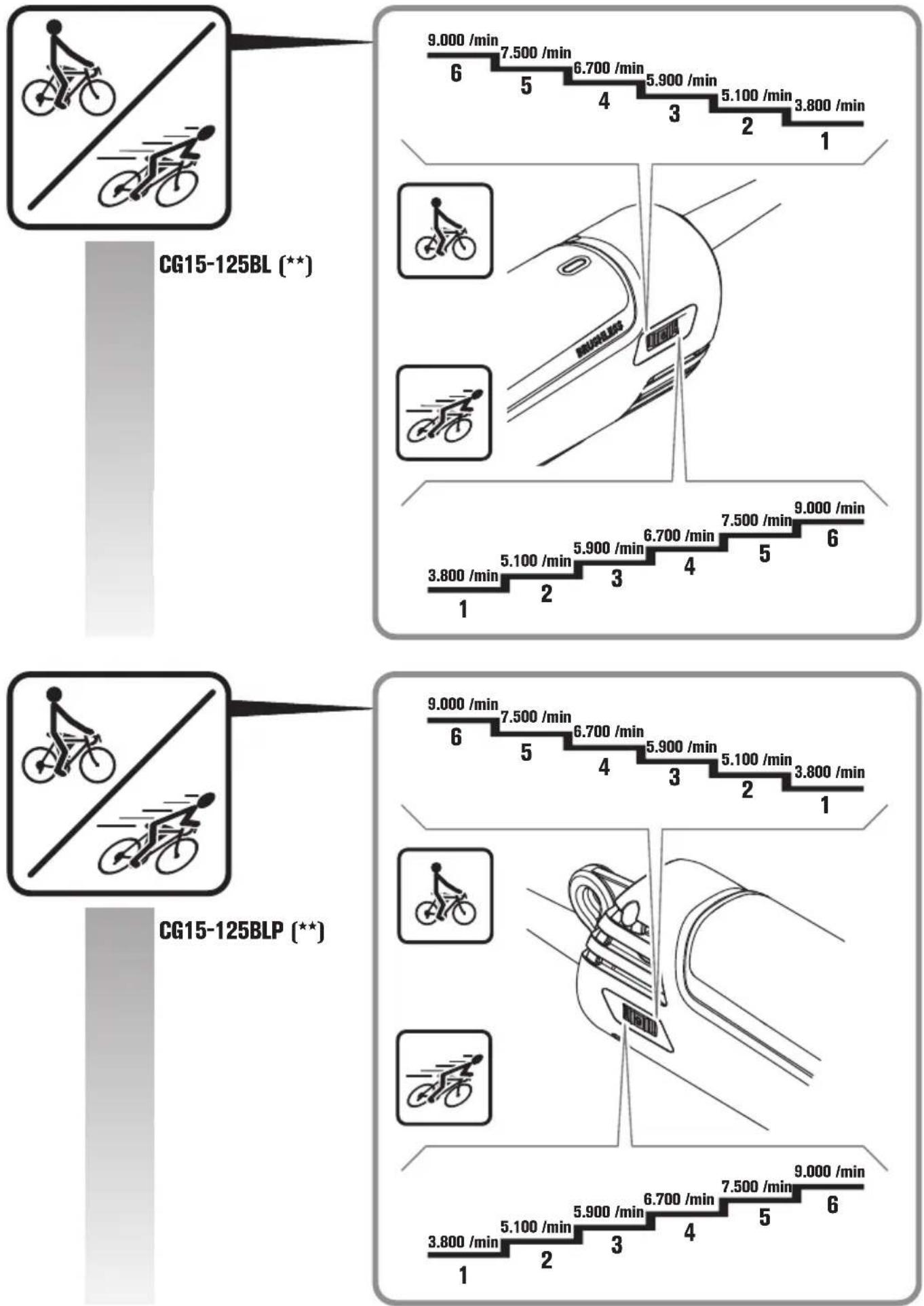
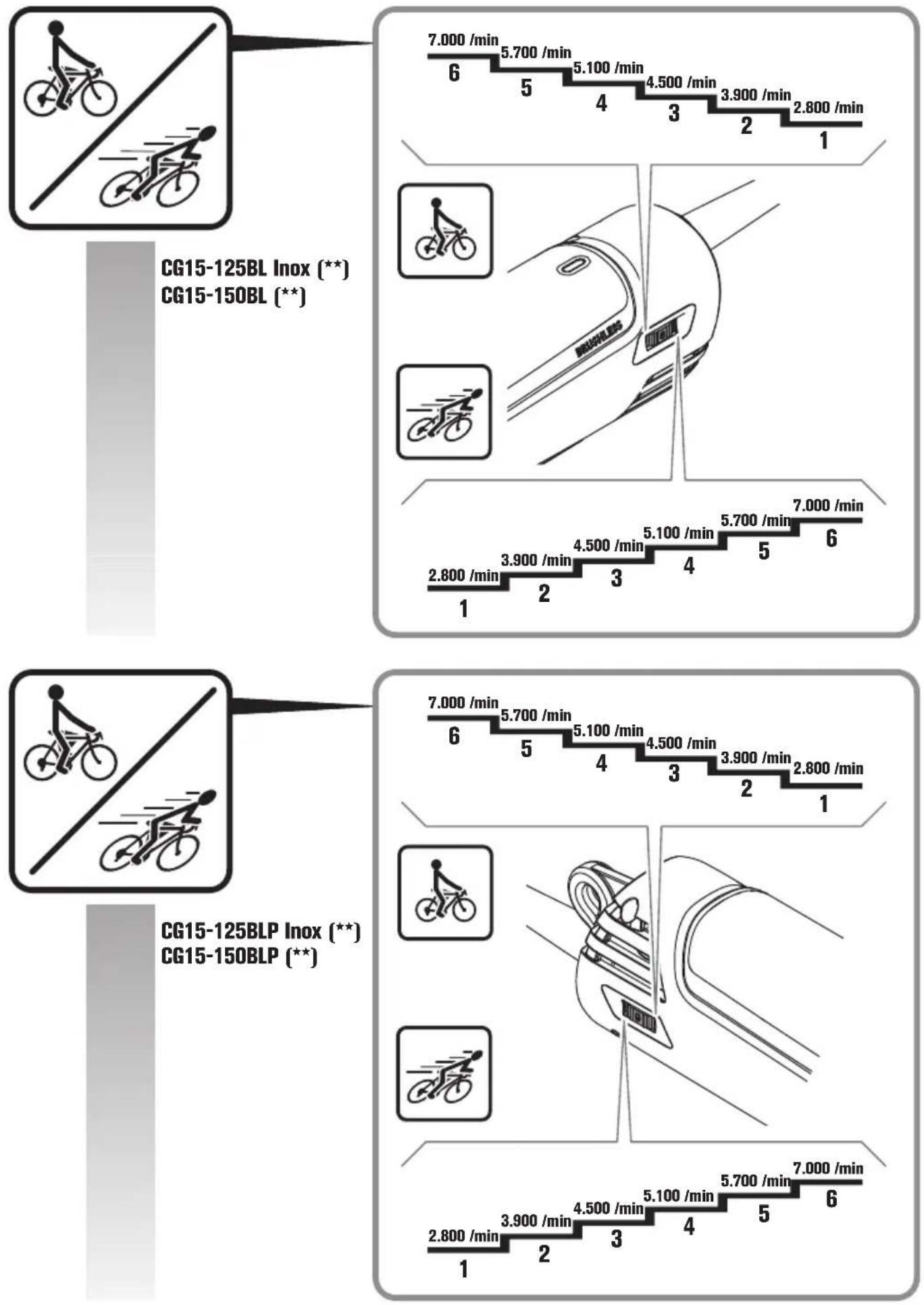
| n | /min, min-1,rpm, r/min | 3800-9000 | 2800-7000 | 2800-7000 | 2800-7000 |
| n_0 | /min, min-1,rpm, r/min | 9000 7000 7000 7000 | |||
| [IMAGE] | ∅_D mm 125 150 150 125 | ||||
| ∅_H mm | 22,23 | 22,23 | 22,23 | 22,23 | |
| T_A-1 mm | 1-6 | 1-6 | 1-6 | 1-6 | |
| T_B-1 mm | 1-6 | 1-6 | 1-6 | 1-6 | |
| T_B-3 mm | 1-6 | 1-6 | 1-6 | 1-6 | |
 | ∅_D mm 125 150 150 125 | ||||
 | M | M14 | M14 | M14 | M14 |
| I mm | 20 | 20 | 20 | 20 | |
 | M | M14 | M14 | M14 | M14 |
| ∅_D mm | 75 | 75 | 75 | 75 | |
| T mm | 30 | 30 | 30 | 30 | |
 | M | M14 | M14 | M14 | M14 |
| ∅_D mm | 82 | 82 | 82 | 82 | |
| kg | 2,3 | 2,6 | 2,6 | 2,4 | |
| L_pA | dB(A) | 91,3 | 90,7 | 90,7 | 90,4 |
| K_pA | dB | 3 | 3 | 3 | 3 |
| L_wA | dB(A) | 99,3 | 98,7 | 98,7 | 98,4 |
| K_wA | dB | 3 | 3 | 3 | 3 |
| L_pCpeak | dB | 105,3 | 106,0 | 104,9 | 104,7 |
| K_pCpeak | dB | 3 | 3 | 3 | 3 |
| a_h,AG | m/s2 | 4,5 | 4,0 | 4,0 | 3,2 |
| a_h,DS | m/s2 | 2,1 | 3,0 | 3,0 | 1,6 |
| K_a | m/s2 | 1,5 | 1,5 | 1,5 | 1,5 |
| ☐ | ☐ | ☐ | ☐ | ||
flowchart
graph TD
    A["Raw Component"] --> B["Add Material"]
    B --> C["Assembly"]
    C --> D["Final Package"]

    subgraph Initial
        E["Raw Component 8"] --> F["Add Material 7"]
        G["Add Material 12"] --> H["Add Material 13"]
        I["Add Material 11"] --> J["Add Material 10"]
    end

    subgraph Final
        K["Add Material 14"] --> L["Add Material 9"]
        M["Add Material 15"] --> N["Add Material 6"]
        O["Add Material 13"] --> P["Add Material 10"]
    end

    style Initial fill:#f9f,stroke:#333
    style Final fill:#ccf,stroke:#333
CG15-125BLP (**)
CG15-150BLP (**)
CG15-125BLP Inox (**)
CG15-125BL (**)
CG15-150BL (**)
CG15-125BL Inox (**)
CG15-125BLP (**)
CG15-150BLP (**)
CG15-125BLP Inox (**)
natural_image
Mechanical assembly diagram showing gear and motor components with no visible text or symbolsAusstattung
Translation of the Original Instructions.
Symbols, abbreviations and terms used.
| Symbol, character Explanation | |
 | General prohibition sign. This action is prohibited. |
 | Do not touch the rotating parts of the power tool. |
 | Observe the instructions in the text or graphic opposite! |
 | Make sure to read the enclosed documents such as the Instruction Manual and the General Safety Instructions. |
 | Before commencing this work step, pull the mains plug out of the socket. Otherwise there will be danger of injury if the power tool should start unintentionally. |
 | Use eye protection during operation. |
 | Use ear protection during operation. |
 | Use protective gloves during operation. |
| [BHWD] | Always operate the power tool with two hands. |
 | Cutting applications with wheel guard, type B, are prohibited for grinding. |
 | A surface that can be touched may be very hot and thus hazardous. |
 | Gripping surface |
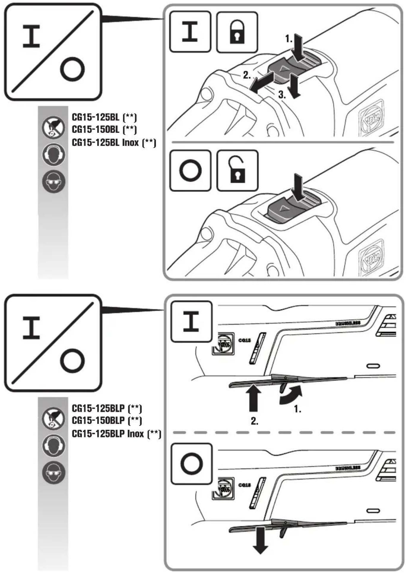
 | Switching on |
 | Switching off |
 | Locked |
 | Not locked |
 | Additional information. |
 | See section “Operating Instructions” |
 | Confirms the conformity of the power tool with the directives of the European Community. |
| [HSXY] | Confirms the conformity of the power tool with the directives of Great Britain (England, Wales, Scotland). |
 US US | This symbol confirms the certification of this product for the USA and Canada. |
 | Confirms the conformity of the power tool with the national technical regulations of the Customs Union (Belarus, Russia, Kyrgyzstan, Kazakhstan and Armenia). |
 | Applies only for China:The duration of environmental protection under normal use of the product is 10 years. |
 WARNING WARNING | This sign indicates a possible dangerous situation that could cause severe or fatal injury.Worn out power tools and other electrotechnical and electrical products should be sorted separately for environmental-friendly recycling. |
 | Identifies recyclable packaging and products that must be collected and disposed of separately. |
| [Seawal] | Product with double or reinforced insulation |
 | Low speed |
 | High speed |
| ~ (a. c.) Alternating current | |
| (Ax - Zx) Marking for internal purposes | |
| (**) May contain numbers and letters | |
| Character Unit of measurement, international | Explanation | |
 | /min, min ^-1 , rpm, r/min Speed range | |
 | /min, min ^-1 , rpm, r/min Rated no-load speed | |
| [S38] | W Power input | |
| [C54K] | W Output | |
| [TXK] | R | a t e |
| [OR-TX] frequency | ||
| [8V4T] | mm Size of metric thread | |
| [W2Z4] | mm Diameter of a round part | |
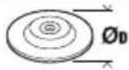
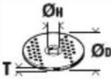 | mm | _D=Max. diameter of grinding/cutting disc _H=Diameter of mounting hole T_A-1=Thickness of application tool for protection guard A-1 T_B-1=Thickness of application tool for protection guard B-1 T_B-3=Thickness of application tool for safety cover B-3 |
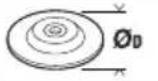 | mm | _D=Max. sanding pad diameter |
 | mm M=Thread for clamping flangeI=Length of mounting thread | |
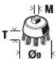
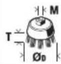 | mm | _D=max. cup brush diameter M=Thread for clamping flange / application toolT=max. wire length |
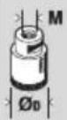
 | mm | _D=Max. diameter diamond hole cutter M=Thread for clamping flange / application tool |
 | kg | Weight according to EPTA-Procedure 01 |
 | dB(A) | Sound pressure level |
| [ADHX] | dB(A) | Sound power level |
| [ZWIZ]eak | dB Peak sound pressure level | |
| [WCWH] | Uncertainty | |
| [DDTX] | m/s ^2 | Vibrational emission value according to EN 62841 (vector sum of three directions) |
| [ESAW] | ||
| [DAOK] | m/s ^2 | Mean vibrational value for angle grinding |
| Character Unit of measurement, international | Explanation |
| a_h,DS | m/s^2 Mean vibrational value for sanding with sanding sheet |
| m, s, kg, A, mm, V, W, Hz, N, °C, dB, min, m/s^2 Basic and derived units of measurement from the international system of units SI. |
For your safety.

Read all safety warnings and all instructions. Failure to follow the
warnings and instructions may result in electric shock, fire and/or serious injury.
Save all warnings and instructions for future reference.

Do not use this power tool before you have thoroughly read and completely understood this Instruction Manual and the enclosed "General
Safety Instructions" (document number
3 41 30 465 06 0). The documents mentioned should be kept for later use and enclosed with the power tool, should it be passed on or sold.
Please also observe the relevant national industrial safety regulations.
Intended use of the power tool:
Hand-guided angle grinder for dry grinding, wire brushing and cutting of metal and stone as well as for cutting tiles in weather-protected environments without the use of liquid coolants, using the application tools and accessories recommended by FEIN.
In environments subject to interference, a reduction of the operating quality is possible; this can include temporary failure, temporary reduction of the function or the intended operating behaviour, for the correction of which intervention by the operator is required.
This power tool is also suitable for use with AC generators with sufficient power output that correspond to the Standard ISO 8528, design type G2. This Standard is particularly not complied with when the so-called distortion factor exceeds 10 %. When in doubt, please refer to the generator instruction/specification guide.
Observe the operating instructions and the national regulations for the installation and operation of the AC generator.
The power tool is not intended for working light metals and for polishing. The operator is solely liable for any damage caused by use not as intended for.
Generally recognized accident prevention regulations and enclosed safety instructions must be observed.
Safety warnings common for grinding, sanding, wire brushing or cutting-off operations
This power tool is intended to function as a grinder, sander, wire brush, hole cutter or cut-off tool. Read all safety warnings, instructions, illustrations and specifications provided with this power tool. Failure to follow all instructions listed below may result in electric shock, fire and/or serious injury.
Operations such as polishing are not to be performed with this power tool. Operations for which the power tool was not designed may create a hazard and cause personal injury.
Do not convert this power tool to operate in a way which is not specifically designed and specified by the tool manufacturer. Such a conversion may result in a loss of control and cause serious personal injury.
Do not use accessories which are not specifically designed and specified by the tool manufacturer. Just because the accessory can be attached to your power tool, it does not assure safe operation.
The rated speed of the accessory must be at least equal to the maximum speed marked on the power tool.
Accessories running faster than their rated speed can break and fly apart.
The outside diameter and the thickness of your accessory must be within the capacity rating of your power tool. Incorrectly sized accessories cannot be adequately guarded or controlled.
The dimensions of the accessory mounting must fit the dimensions of the mounting hardware of the power tool. Accessories that do not match the mounting hardware of the power tool will run out of balance, vibrate excessively and may cause loss of control.
Do not use a damaged accessory. Before each use inspect the accessory such as abrasive wheels for chips and cracks, backing pad for cracks, tear or excess wear, wire brush for loose or cracked wires. If power tool or accessory is dropped, inspect for damage or install an undamaged accessory. After inspecting and installing an accessory, position yourself and bystanders away from the plane of the rotating accessory and run the power tool at maximum no-load speed for one minute. Damaged accessories will normally break apart during this test time.
Wear personal protective equipment. Depending on application, use face shield, safety goggles or safety glasses. As appropriate, wear dust mask, hearing protectors, gloves and workshop apron capable of stopping small abrasive or workpiece fragments. The eye protection must be capable of stopping flying debris generated by various applications. The dust mask or respirator must be capable of filtrating particles generated by the particular application. Prolonged exposure to high intensity noise may cause hearing loss.
Keep bystanders a safe distance away from work area. Anyone entering the work area must wear personal protective equipment. Fragments of workpiece or of a broken accessory may fly away and cause injury beyond immediate area of operation.
Hold the power tool by insulated gripping surfaces only, when performing an operation where the cutting accessory may contact hidden wiring or its own cord. Cutting accessory contacting a "live" wire may make exposed metal parts of the power tool "live" and could give the operator an electric shock.
Position the cord clear of the spinning accessory. If you lose control, the cord may be cut or snagged and your hand or arm may be pulled into the spinning accessory.
Never lay the power tool down until the accessory has come to a complete stop. The spinning accessory may grab the surface and pull the power tool out of your control.
Do not run the power tool while carrying it at your side. Accidental contact with the spinning accessory could snag your clothing, pulling the accessory into your body.
Regularly clean the power tool's air vents. The motor's fan will draw the dust inside the housing and excessive accumulation of powdered metal may cause electrical hazards.
Do not operate the power tool near flammable materials. Sparks could ignite these materials.
Do not use accessories that require liquid coolants.
Using water or other liquid coolants may result in electrocution or shock.
Kickback and related warnings
Kickback is a sudden reaction to a pinched or snagged rotating wheel, backing pad, brush or any other accessory. Pinching or snagging causes rapid stalling of the rotating accessory which in turn causes the uncontrolled power tool to be forced in the direction opposite of the accessory's rotation at the point of the binding.
For example, if an abrasive wheel is snagged or pinched by the workpiece, the edge of the wheel that is entering into the pinch point can dig into the surface of the material causing the wheel to climb out or kick out. The wheel may either jump toward or away from the operator, depending on direction of the wheel's movement at the point of pinching. Abrasive wheels may also break under these conditions.
Kickback is the result of power tool misuse and/or incorrect operating procedures or conditions and can be avoided by taking proper precautions as given below.
Maintain a firm grip with both hands on the power tool and position your body and arms to allow you to resist kickback forces. Always use auxiliary handle, if provided, for maximum control over kickback or torque reaction during start-up. The operator can control torque reactions or kickback forces, if proper precautions are taken.
Never place your hand near the rotating accessory.
Accessory may kickback over your hand.
Do not position your body in the area where power tool will move if kickback occurs. Kickback will propel the tool in direction opposite to the wheel's movement at the point of snagging.
Use special care when working corners, sharp edges, etc. Avoid bouncing and snagging the accessory. Corners, sharp edges or bouncing have a tendency to snag the rotating accessory and cause loss of control or kickback.
Do not attach a saw chain woodcarving blade, segmented diamond wheel with a peripheral gap greater than 10 mm or toothed saw blade. Such blades create frequent kickback and loss of control.
Safety warnings specific for grinding and cutting-off operations
Use only wheel types that are specified for your power tool and the specific guard designed for the selected wheel. Wheels for which the power tool was not designed cannot be adequately guarded and are unsafe.
The grinding surface of centre depressed wheels must be mounted below the plane of the guard lip. An improperly mounted wheel that projects through the plane of the guard lip cannot be adequately protected.
The guard must be securely attached to the power tool and positioned for maximum safety, so the least amount of wheel is exposed towards the operator. The guard helps to protect the operator from broken wheel fragments, accidental contact with wheel and sparks that could ignite clothing.
Wheels must be used only for specified applications. For example: do not grind with the side of cut-off wheel. Abrasive cut-off wheels are intended for peripheral grinding, side forces applied to these wheels may cause them to shatter.
Always use undamaged wheel flanges that are of correct size and shape for your selected wheel. Proper wheel flanges support the wheel thus reducing the possibility of wheel breakage. Flanges for cut-off wheels may be different from grinding wheel flanges.
Do not use worn down wheels from larger power tools. A wheel intended for larger power tool is not suitable for the higher speed of a smaller power tool and may burst.
When using dual purpose wheels always use the correct guard for the application being performed. Failure to use the correct guard may not provide the desired level of guarding, which could lead to serious injury.
Additional safety warnings specific for cutting off operations
Do not “jam” the cut-off wheel or apply excessive pressure. Do not attempt to make an excessive depth of cut. Overstressing the wheel increases the loading and susceptibility to twisting or binding of the wheel in the cut and the possibility of kickback or wheel breakage.
Do not position your body in line with and behind the rotating wheel. When the wheel, at the point of operation, is moving away from your body, the possible kickback may propel the spinning wheel and the power tool directly at you.
When wheel is binding or when interrupting a cut for any reason, switch off the power tool and hold it motionless until the wheel comes to a complete stop. Never attempt to remove the cut-off wheel from the cut while the wheel is in motion otherwise kickback may occur. Investigate and take corrective action to eliminate the cause of wheel binding.
Do not restart the cutting operation in the workpiece. Let the wheel reach full speed and carefully re-enter the cut. The wheel may bind, walk up or kickback if the power tool is restarted in the workpiece.
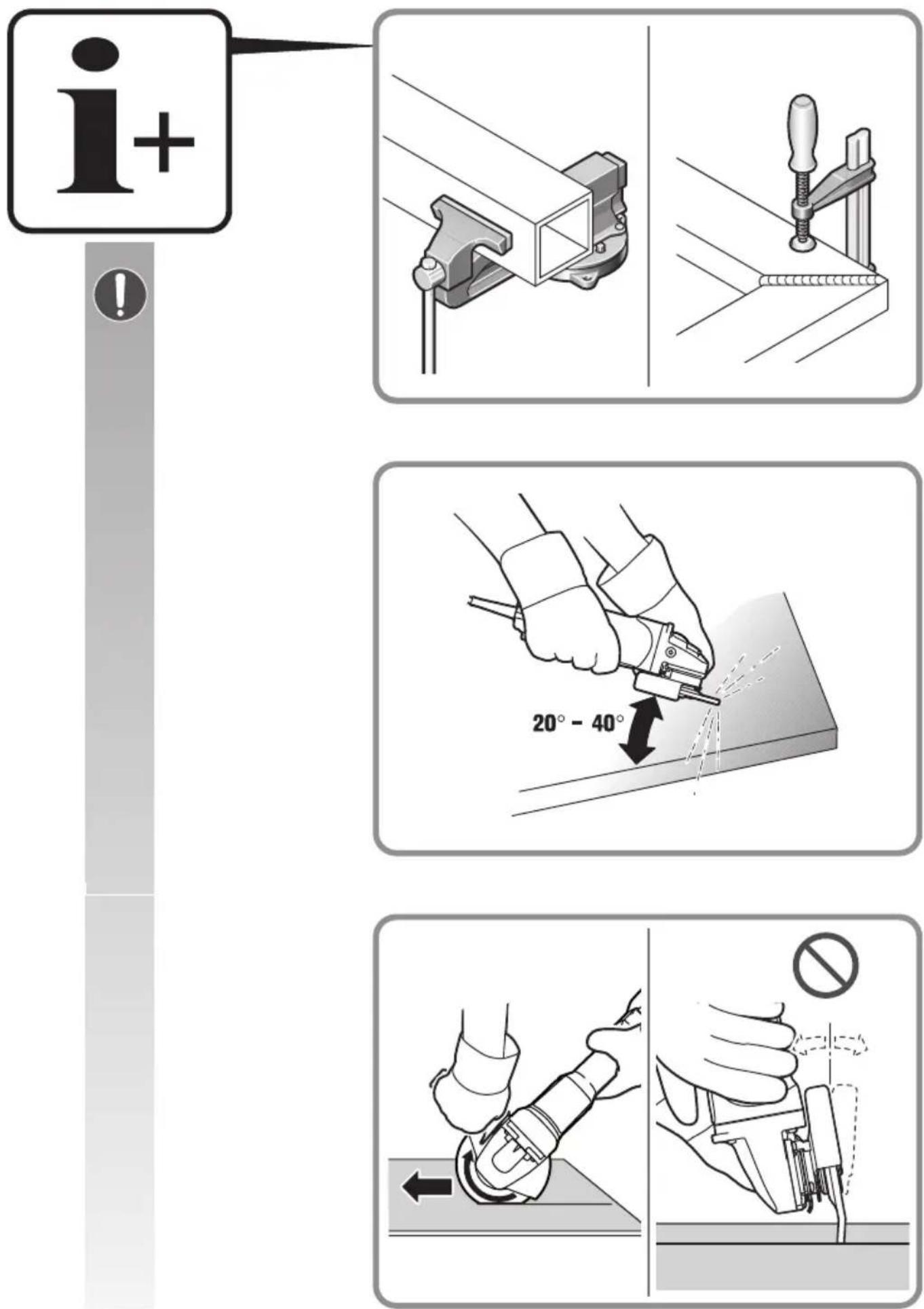
Support panels or any oversized workpiece to minimize the risk of wheel pinching and kickback. Large workpieces tend to sag under their own weight. Supports must be placed under the workpiece near the line of cut and near the edge of the workpiece on both sides of the wheel.
Use extra caution when making a "pocket cut" into existing walls or other blind areas. The protruding wheel may cut gas or water pipes, electrical wiring or objects that can cause kickback.
Do not attempt to do curved cutting. Overstressing the wheel increases the loading and susceptibility to twisting or binding of the wheel in the cut and the possibility of kickback or wheel breakage, which can lead to serious injury.
Safety warnings specific for sanding operations Use proper sized sanding disc paper. Follow manufacturers recommendations, when selecting sanding paper. Larger sanding paper extending too far beyond the sanding pad presents a laceration hazard and may cause snagging, tearing of the disc or kickback.
Safety warnings specific for wire brushing operations
Be aware that wire bristles are thrown by the brush even during ordinary operation. Do not overstress the wires by applying excessive load to the brush. The wire bristles can easily penetrate light clothing and/or skin.
If the use of a guard is specified for wire brushing, do not allow any interference of the wire wheel or brush with the guard. Wire wheel or brush may expand in diameter due to work load and centrifugal forces.
- When using a Type A wheel guard (cut-off wheel guard) for facial grinding, the wheel guard may interfere with the workpiece causing poor control.
- When using a Type B wheel guard (grinding wheel guard) for cutting-off operations with bonded abrasive wheels, there is an increased risk of exposure to emitted sparks and particles, as well as exposure to wheel fragments in the event of wheel burst.
Further safety warnings
Do not use a damaged power tool. Before each use of the power tool, check the housing and other components for damage such as cracks or breakage.
When grinding thin metal sheet or other well vibrating structures with large surface area, take appropriate measures such as using heavy flexible damping mats.
Otherwise, a much higher overall noise emission may occur than the specified noise emission of the power tool. Also consider the increased noise emission for risk assessment of noise exposure and for selection of appropriate hearing protection.
Do not wear easily flammable clothing. Sparks could cause such clothing to ignite.
Use elastic spacers/liners when these are provided with the grinding accessory.
Offset grinding discs must be mounted in such a manner that their grinding surface is 2 mm below the bottom edge the of the wheel guard. Grinding accessories that do not meet these requirements cannot be adequately covered off and are not permitted.
Make sure that the application tools are mounted in accordance with the manufacturers instructions. The mounted application tools must be able to rotate freely. Incorrectly mounted application tools can become loose during operation and be thrown from the machine.
The thread length of application tools with threaded insert must greater than the spindle length I (see page 2). This allows the application tool to be securely fastened to the power tool over the entire spindle length.
Handle grinding accessories carefully and store them according to the manufacturer's instructions. Damaged grinding accessories can develop cracks and burst during operation.
When using application tools with a threaded insert, take care that the thread in the application tool is long enough to hold the spindle length of the power tool. The thread in the application tool must match the thread on the spindle. Incorrectly mounted application tools can loosen during operation and cause injuries.
Do not direct the power tool against yourself, other persons or animals. Danger of injury from sharp or hot application tools.
Beware of any concealed electric cables, gas or water conduits. Check the working area before commencing work, e. g. with a metal detector.
Use a stationary extraction system and frequently blow out the ventilation slots. When working metal under extreme operating conditions, it is possible for conductive dust to settle in the interior of the power tool. The total insulation of the power tool can be impaired.
Do not rivet or screw any name-plates or signs onto the power tool. If the insulation is damaged, protection against an electric shock will be ineffective.
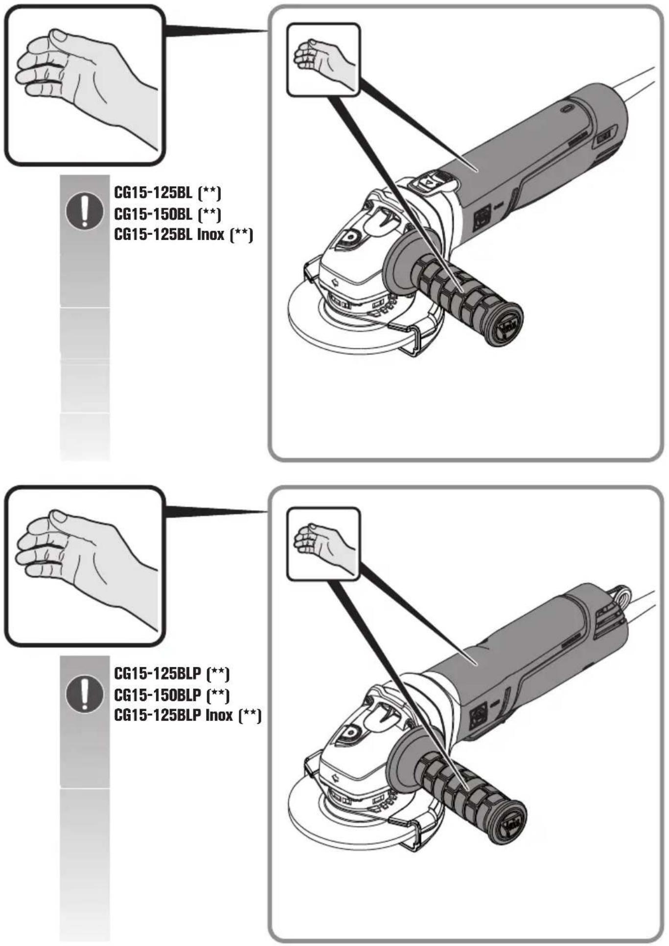
Always work with the auxiliary handle. The auxiliary handle ensures reliable guiding of the power tool.
After working gypsum-containing materials: Blow out the ventilation openings of the power tool and the switch element with dry and oil-free compressed air.
Otherwise, gypsum-containing dust can settle in the power tool housing and switch element, which can harden in connection with humidity. This can impair the switching mechanism.
Before putting into operation, check the mains connection and the mains plug for damage.
Observe the mains voltage! The voltage of the power source must correspond with the data on the type plate of the power tool.
Recommendation: The tool should always be supplied with power via a residual current device (RCD) with a rated current of 30 mA or less.
Vibration and noise emission values
The vibration and noise emission values given in these instructions have been measured according to a measurement method standardised in EN 62841 and can be used to compare power tools with each other. They are also suitable for a preliminary assessment of vibration and noise exposure.
The given vibration and noise emission values represent the main applications of the power tool.
However, if the power tool is used for other applications, with deviating application tools or insufficient maintenance, the overall vibration values and the noise emission values may differ. This can significantly increase the vibration and noise exposure over the total working period.
For an accurate estimation of vibration and noise exposure, the durations when the equipment is switched off or running but not actually in use should also be taken into account. This may significantly reduce the vibration and noise exposure over the total working period.
Identify additional safety measures to protect the operator from the effects of vibration and noise such as: Maintain the power tool and the accessories, keep the hands warm, organization of work patterns.
Handling hazardous dusts
For work procedures with this power tool where material is removed, dusts develop that can be hazardous to one's health.
Contact with or inhaling some dust types, e. g. asbestos and asbestos-containing materials, lead-containing coatings, metal, some wood types, minerals, silicate particles from materials containing stone, paint solvents, wood preservatives, antifouling paints for vessels, can trigger allergic reactions to the operator or bystanders and/or lead to respiratory infections, cancer, birth defects or other reproductive harm. The risk from inhaling dusts depends on the exposition. Use dust extraction matched appropriately for the developing dust, as well as personal protective equipment and provide for good ventilation of the workplace. Leave the processing of asbestos-containing materials to specialists.
Wood and light-metal dust, hot mixtures of grinding dust and chemical materials can self-ignite under unfavourable conditions or cause an explosion. Avoid sparking in the direction of the dust collector as well as overheating of the power tool and the materials being sanded, empty the dust collector/container in time, observe the material manufacturer's working instructions, as well as the relevant regulations in your country for the materials being worked.
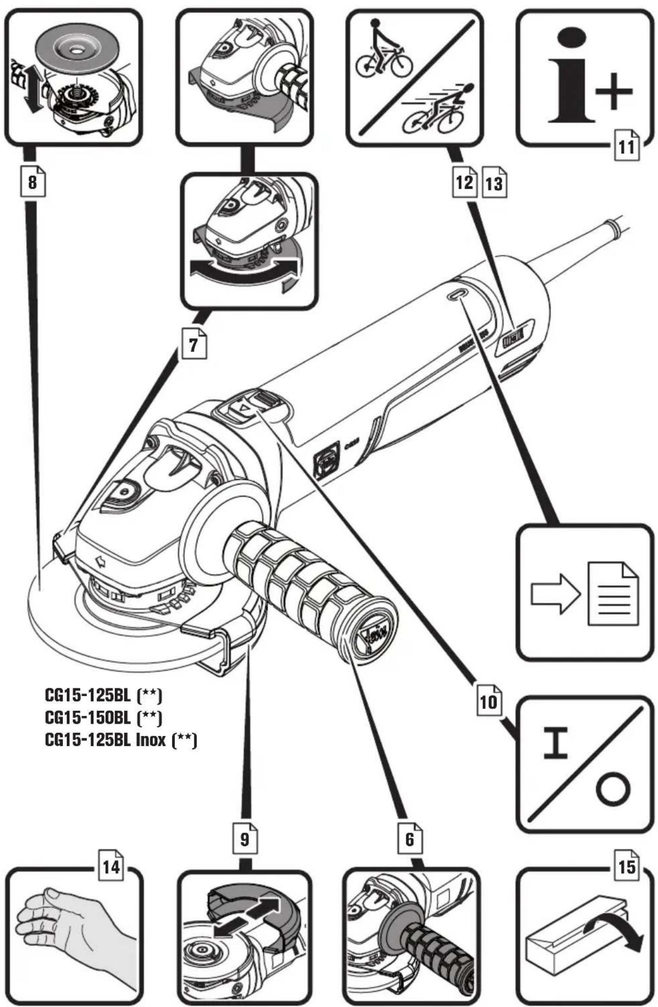
Operating Instructions.
Press the locking button only when the motor is stopped (see page 8). Otherwise the power tool may be damaged.
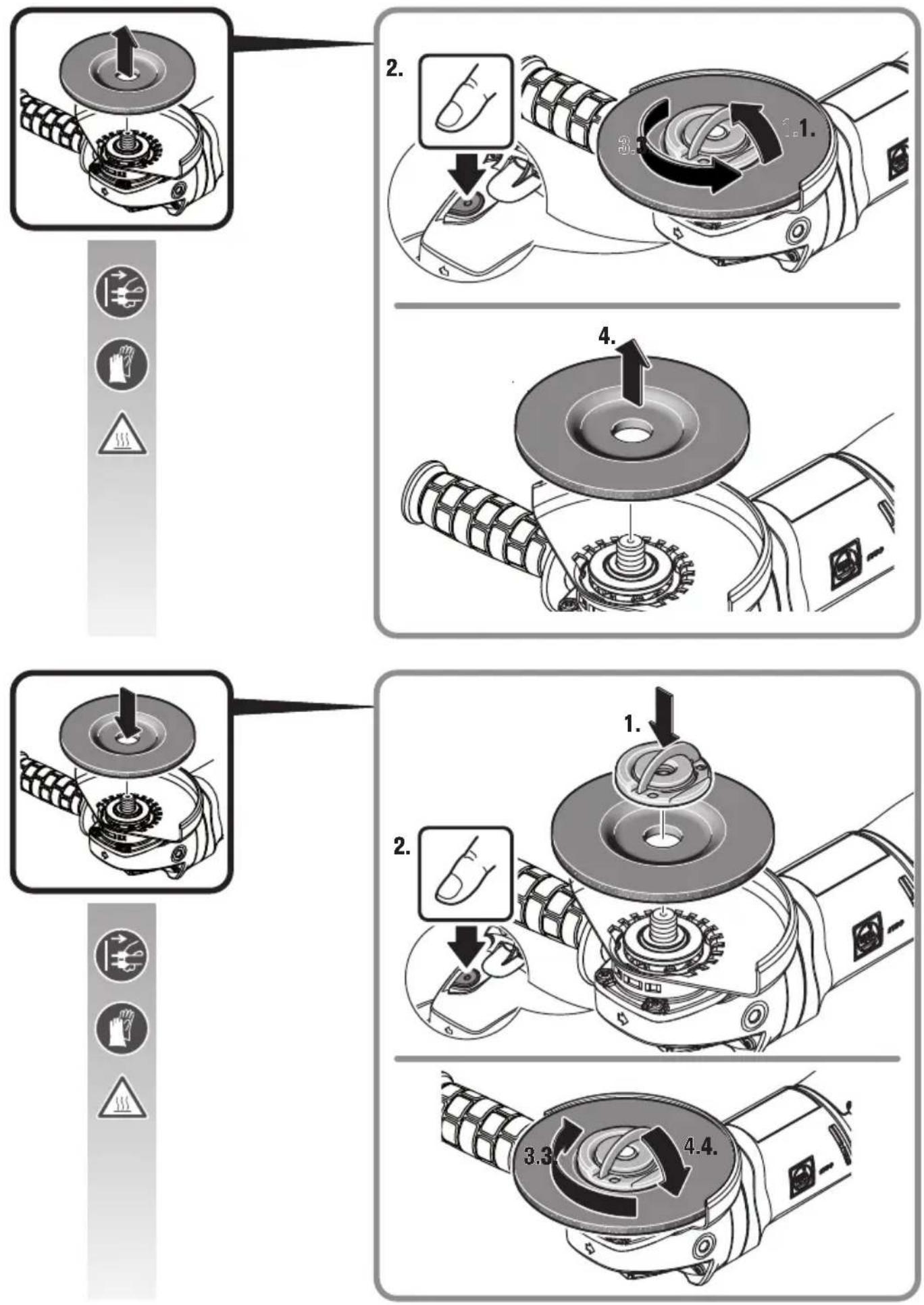
Changing the tool
Observe the correct mounting direction of the quick-clamping nut.
Offset grinding discs must be mounted in such a manner that their grinding surface is 2 mm below the bottom edge the of the wheel guard. Grinding accessories that do not meet these requirements cannot be adequately covered off and are not permitted.
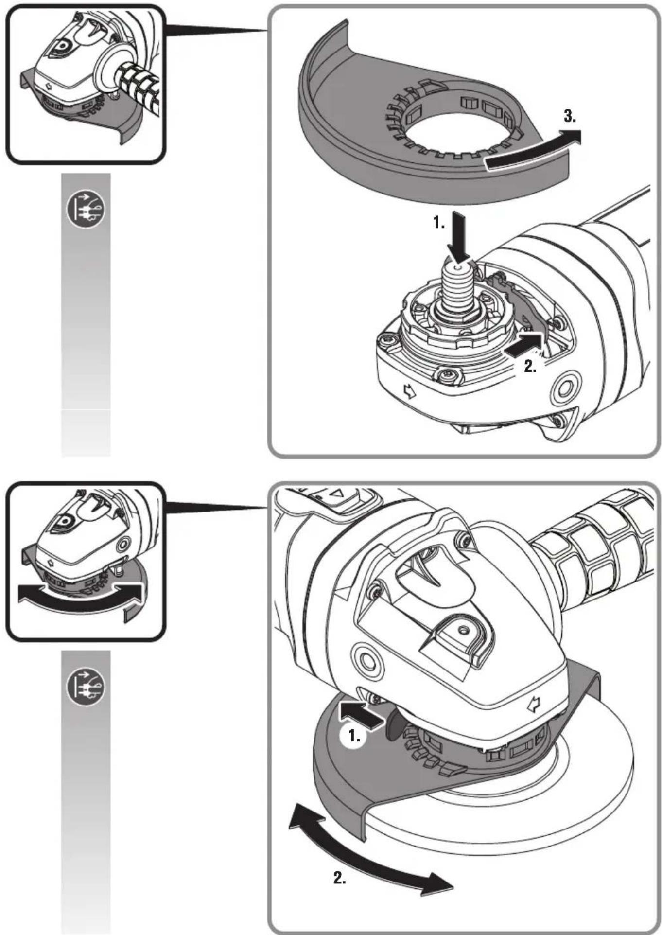
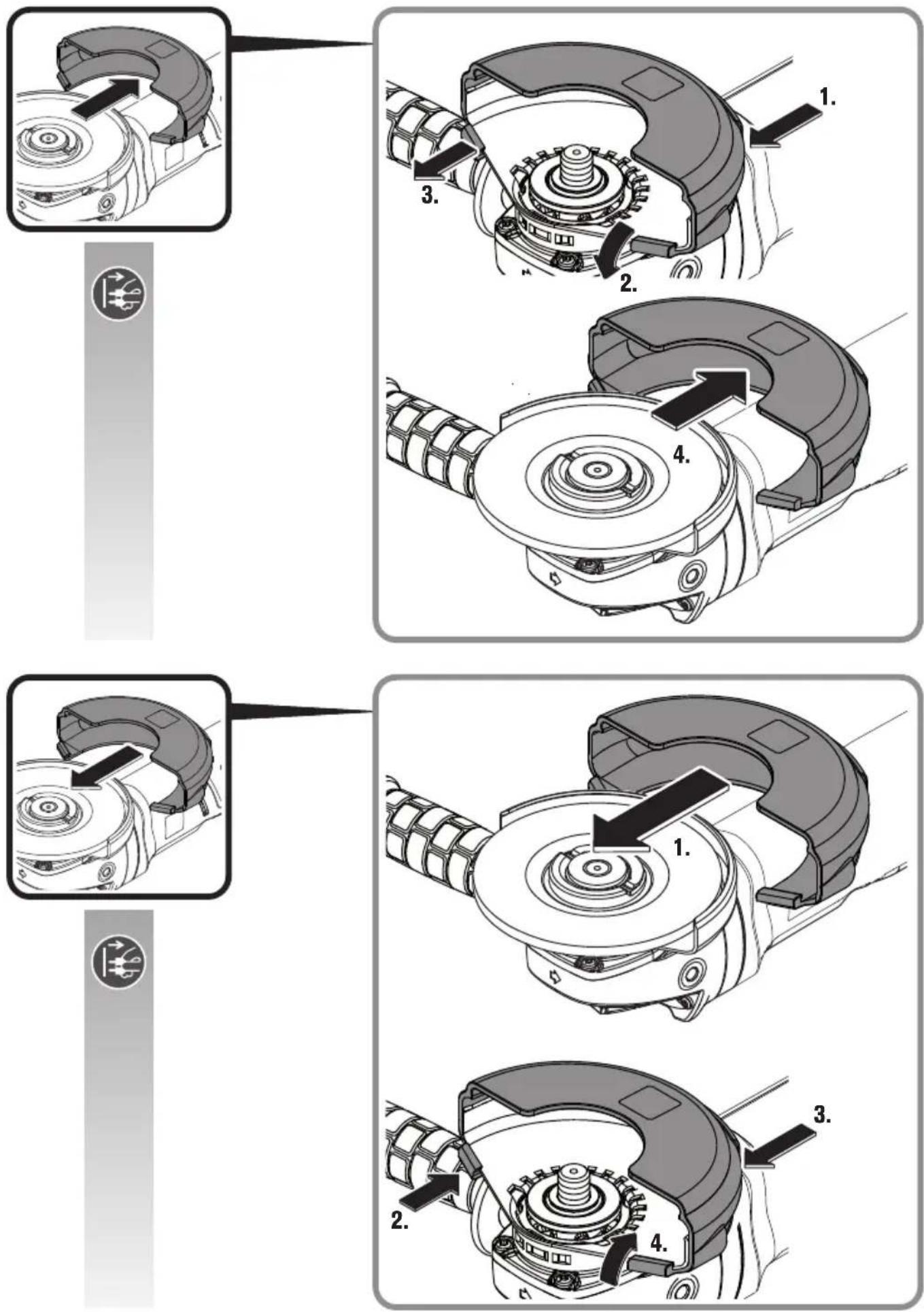
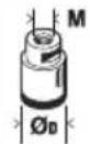
Mounting the safety cover (see page 9)
- Slide the safety cover over the wheel guard. - Pay attention that the two engaging hooks are fully engaged.
natural_image
Technical diagram of a mechanical device with gear and adjustment knobs (no text or symbols)Features
The soft start is used to reduce torque reaction forces when switching on and running up the power tool to the no-load speed.
The restarting protection prevents the power tool from automatically restarting if the power supply is interrupted during operation. In this case, switch off the power tool, check the power supply and then switch the power tool on again.
The blocking monitor reduces the risk of motor damage and the risk of accidents when an application tool blocks. In this case, the power tool switches off automatically. Afterwards, set the switch to the off position, remove the power tool from the workpiece and check the application tool for damage. Afterwards, switch the power tool on again.
The electronic overload protection reduces the risk of motor damage if the power tool is overloaded. In this case, the power tool switches off automatically. Afterwards, set the switch to the off position, remove the power tool from the workpiece and check the application tool for damage. Afterwards, switch the power tool on again.
The electronic speed preselection enables the speed to be adapted to the respective application and the respective application tool.
The kickback monitoring reduces the risk of unexpected kickback of the power tool. In this case, the power tool switches off automatically. Afterwards, set the switch to the off position, remove the power tool from the workpiece and check the application tool for damage. Afterwards, switch the power tool on again.
The power tool is equipped with a brake system for braking down the application tool. This reduces the risk of accidents.
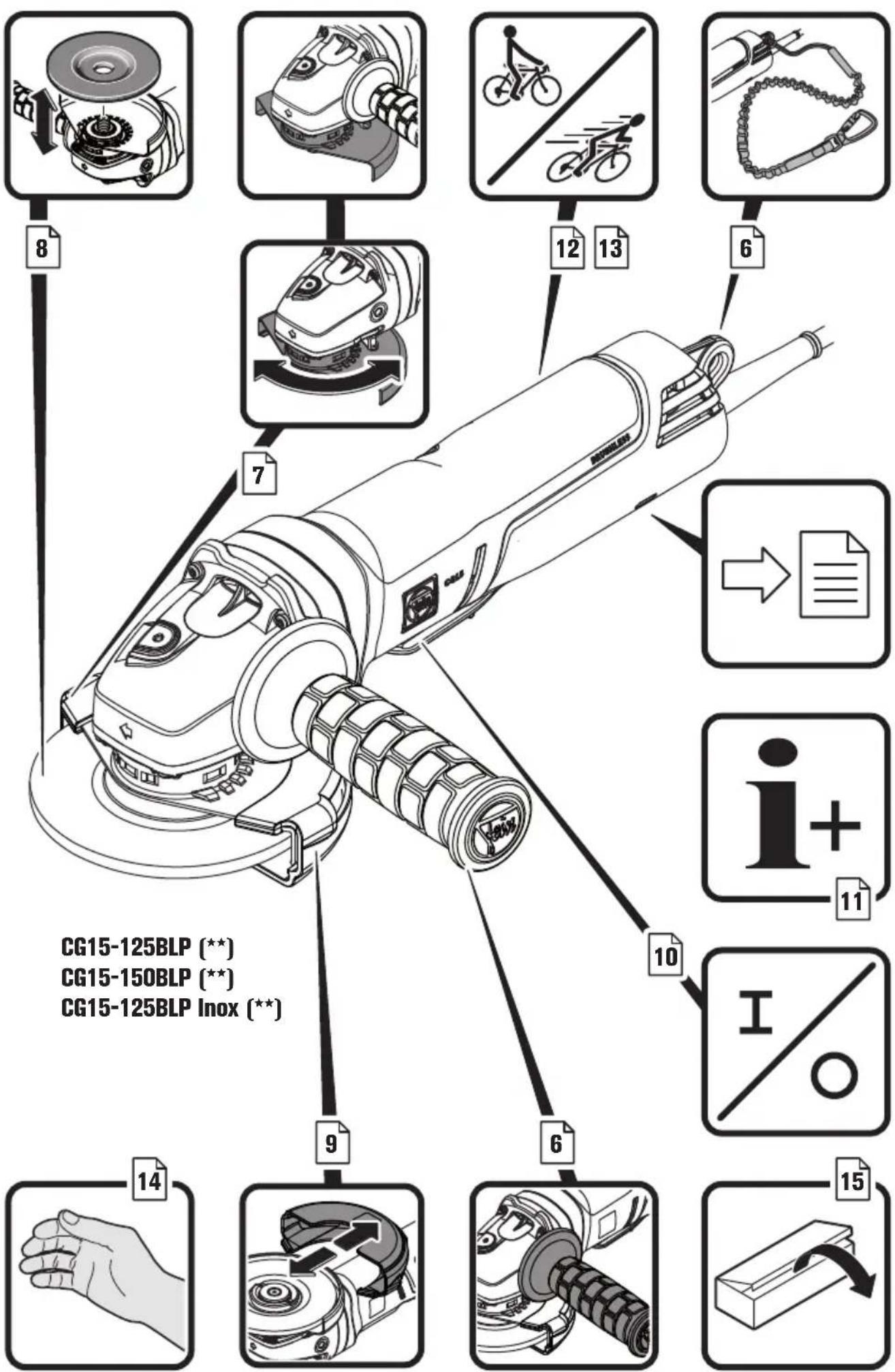
Only for CG15-125BLP ( ^** ), CG15-150BLP ( ^** ), CG15-125BLP Inox ( ^** ):
The dead man's switch is a non-lockable switch. The dead man's switch must be continuously actuated to keep the power tool in operation.
Meaning of the LED indicator.

When errors occur that are not listed in the following table, please the after-sales service.
| Green LED | State | Explanation |
| Lit Operational readiness | Normal condition as soon as plug is connected to mains, also during operation. | |
| Flashing Thermal overload | Warning against and signaling of thermal overload shut-off. In addition, the user is warned by a noticeable drop in speed (power limitation). | |
| Off Error If the green LED | D is off, an error is present, e.g. defective power cord. |
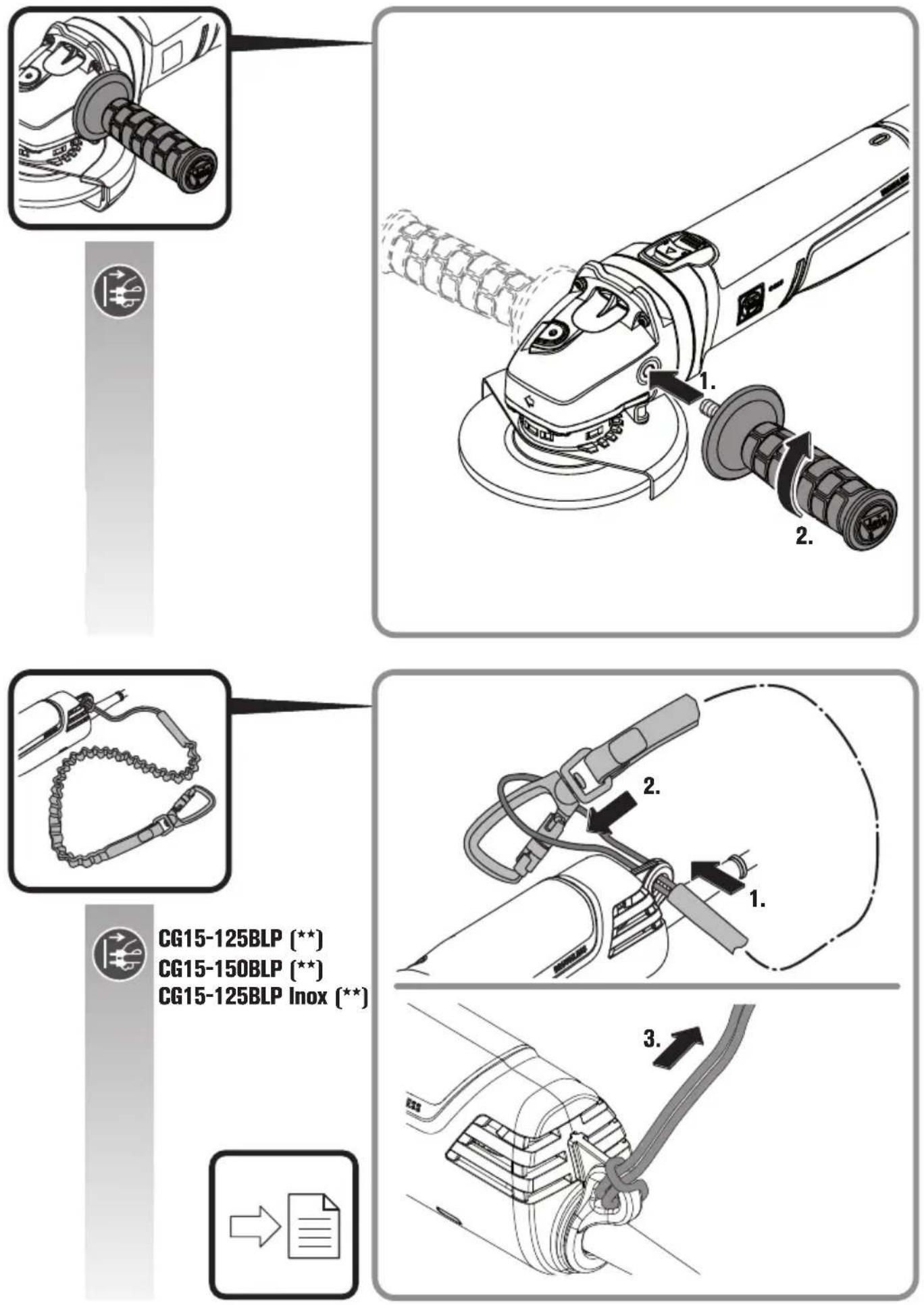
Securing cable
For working at height, suitable securing cables for the product can be fitted at the intended fastening point. Working at height may only be carried out by trained personnel with knowledge of tool safety and the use of tools at height.
WARNING
Only use securing cables that meet the following criteria. Otherwise,
serious or fatal injuries may result.
- Only use securing cables/fall protection devices that fulfill the currently valid requirements of ANSI/ISEA 121 and do not exceed a maximum stretched belt length of 1.2m .
- Ensure that the total weight of the power tool including the mounted accessories does not exceed the maximum allowable load of the securing cable/fall protection system.
Observe the safety and operating instructions enclosed with the securing cable.
Before each use, check the securing cable/fall protection system for damage such as cut, torn or frayed fabric and damaged seams. Damaged securing cables/fall protection devices must not be used and must be replaced immediately.
Before each use, check the fastening point on the power tool for tight seating and damage such as cracks and sharp edges. Loose or damaged fastening points must not be used to attach securing cables/fall protection devices.
Do not use the securing cable/fall protection system to secure yourself and do not attach it to yourself.
Do not attempt to catch a falling power tool.
Do not use the securing cable/fall protection system near moving parts. The securing cable/fall protection could become entangled and cause great hazards.
Before using the securing cable/fall protection, check the tight seating of any detachable parts on the power tool.
Ensure that the use of fall protection does not impair the use of the power tool and its protective devices.
Connect the securing cable to the intended fastening point of the power tool only as shown (see page 6).
Repair and customer service.
Please observe that power tools may only be repaired, maintained and inspected by qualified electricians, as improper maintenance can result in considerable hazards for the user.

When working metal under extreme operating conditions, it is possible for conductive dust to settle in the interior of the power
tool. The total insulation of the power tool can be impaired. Blow out the interior of the power tool via the ventilation slots frequently with dry and oil-free compressed air.
When working gypsum-containing materials, dust can settle within the power tool and switch element, which can harden in connection with humidity. This can impair the switching mechanism. Blow out the interior of the power tool via the ventilation slots and the switch element frequently with dry and oil-free compressed air.
Products that have come into contact with asbestos may not be sent in for repair. Dispose of products contaminated with asbestos according to the applicable country-specific regulations for such disposal.
For FEIN power tools and accessories in need of repair, please contact your FEIN after-sales service. The address can be found on the Internet under www.fein.com.
Renew stickers and warning indications on the power tool when aged and worn.
The current spares parts list for this power tool can be found on our website at www.fein.com.
Use only original spare parts.
If required, you can change the following parts yourself:
Application tools, auxiliary handle, clamping flanges, wheel guard, hand protection
Warranty and liability.
The warranty for the product is valid in accordance with the legal regulations in the country where it is marketed. In addition, FEIN also provides a guarantee in accordance with the FEIN manufacturer's warranty declaration.
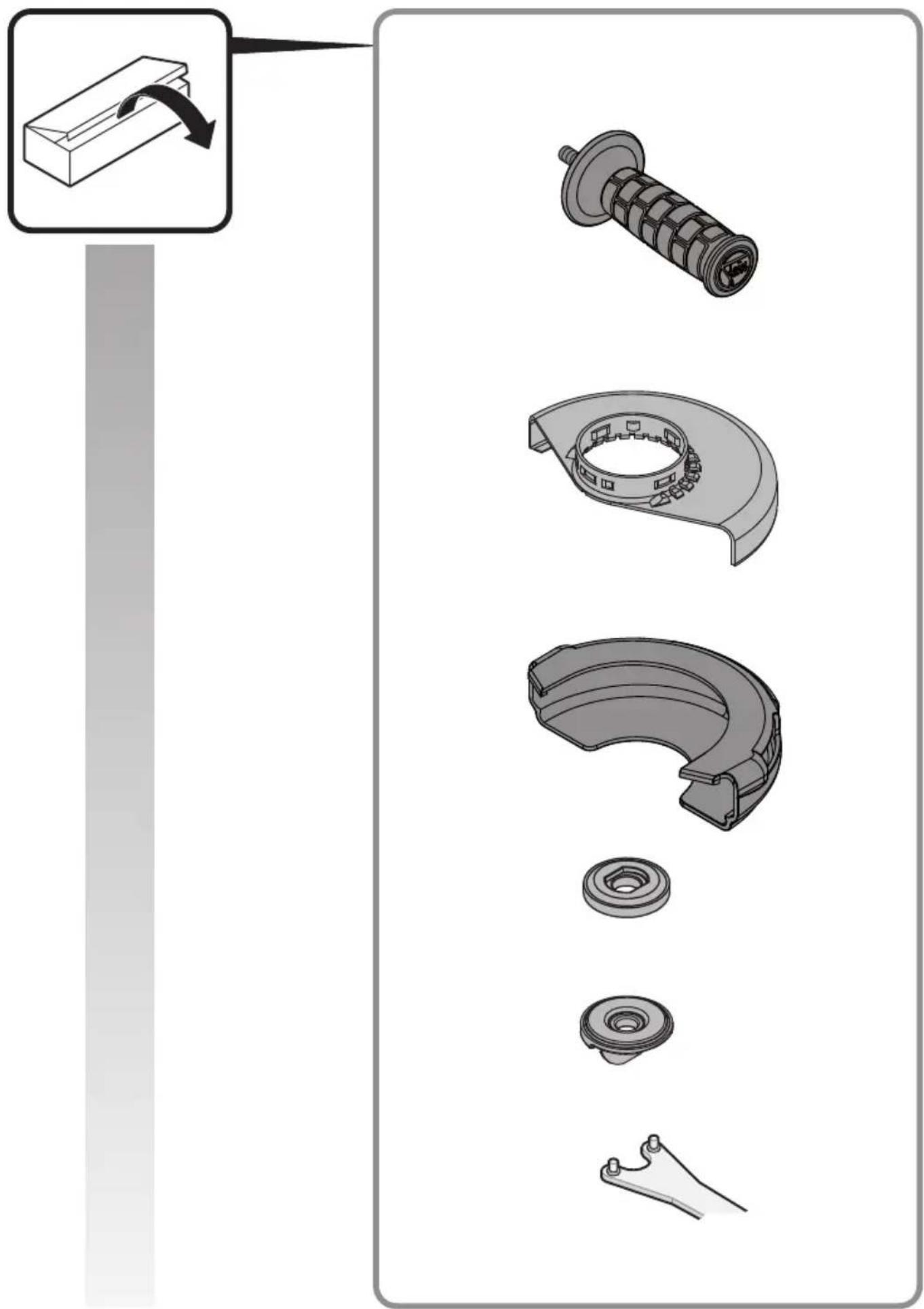
The delivery scope of your power tool may include only a part of the accessories described or shown in this Instruction Manual.
Declaration of conformity.
This CE declaration is only valid for European Union and EFTA (European Free Trade Association) countries and only for products intended for the EU or EFTA market. After placing the product on the EU market the UKCA mark loses its mark validity.
The UKCA declaration is only valid for the Great Britain market (England, Wales and Scotland) and only for products intended for the Great Britain market. After placing the product on the Great Britain market the CE mark loses its mark validity.
Environmental protection, disposal.
Packaging, worn out power tools and accessories should be sorted for environmental-friendly recycling.
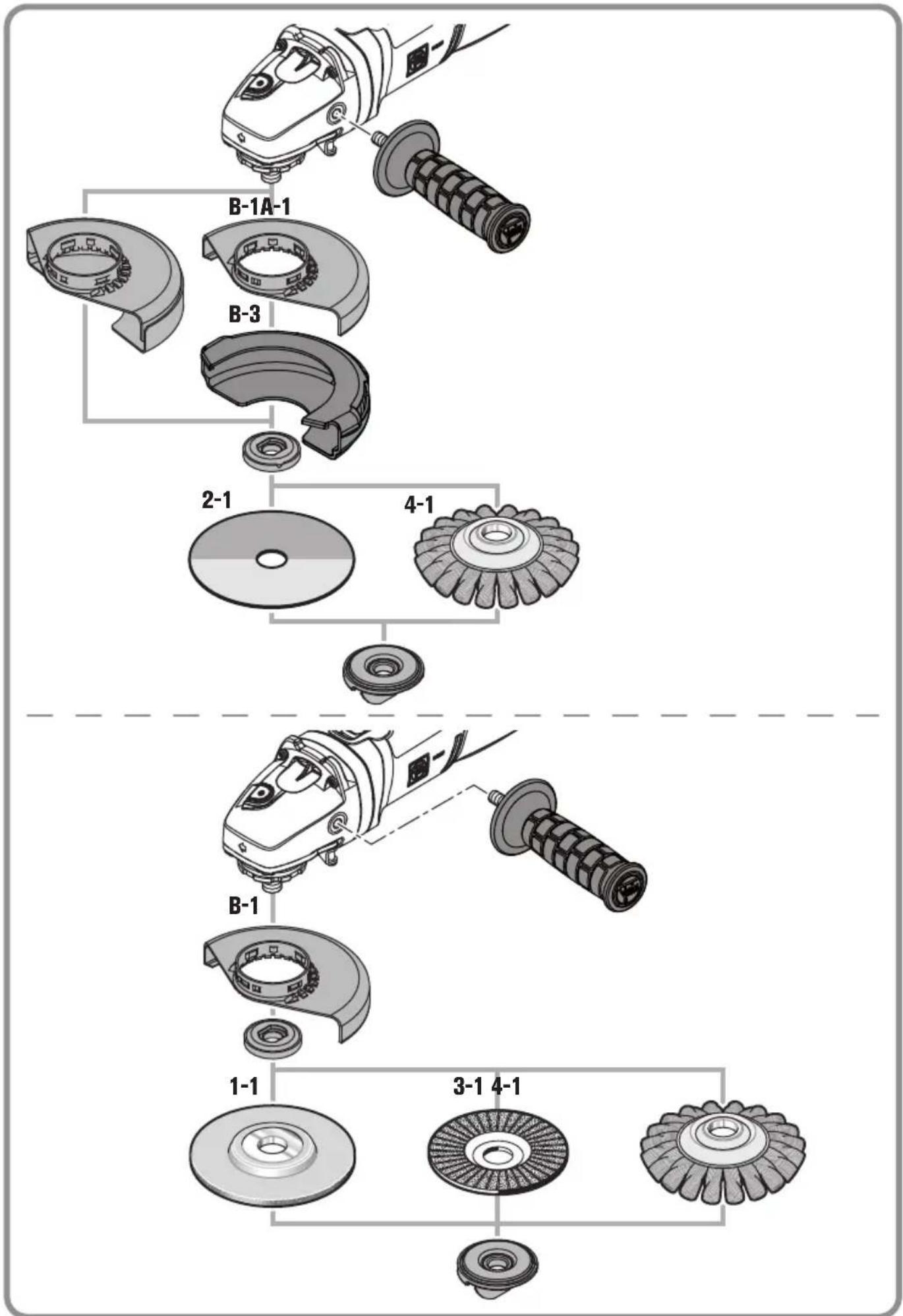
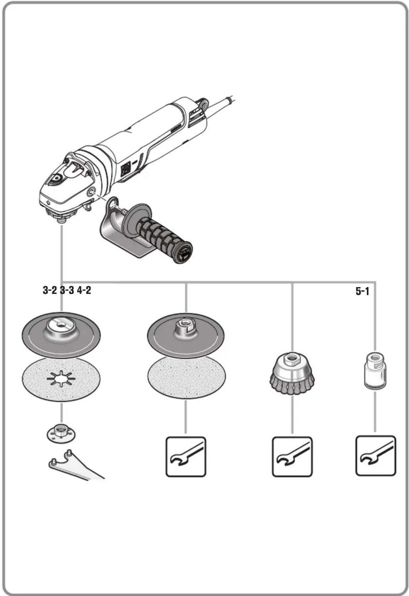
Selection of accessories (see page 16/17).
Use only original FEIN accessories. The accessories must be intended for the power tool type.
A-1 Wheel guard for cutting, type A
B-1 Wheel guard for grinding, type B
B-3 Safety cover for cutting
1-1 Grinding disc, type 27
2-1 Cutting disc
(use only with mounted safety cover)
3-1 Flap discs
3-2 Backing pad for fibre sanding sheets, fibre sanding sheets
(mount only with the provided backing-pad clamping unit)
3-3 Backing pad with Velcro, Velcro sanding sheets, sanding fleece with Velcro attachment, sponges (use a fitting open-end spanner)
4-1 Steel tapered twist brush
4-2 Steel-wire cup brush, flap discs (use a fitting open-end spanner)
5-1 Diamond hole cutter (use fitting open-end spanner)
natural_image
Mechanical assembly diagram showing gear and shaft components with no visible text or symbolsÉquipement
natural_image
Mechanical assembly diagram showing gear and motor components with no visible text or symbolsDotazione
natural_image
Technical diagram of a mechanical assembly with gear and adjustment knobs (no text or labels)Uitvoering
natural_image
Mechanical assembly diagram showing gear and motor components with no visible text or symbolsEquipamiento
natural_image
Mechanical assembly diagram showing gear and motor components with no visible text or symbolsEquipamento
natural_image
Technical diagram of a mechanical assembly with gear and adjustment knobs (no text or symbols)Εξοπλισμός
natural_image
Technical diagram of a mechanical assembly with gears and adjustment knobs (no text or symbols)Udstyr
natural_image
Mechanical assembly diagram showing gear and motor components with no visible text or symbolsUtstyr
natural_image
Technical diagram of a mechanical assembly with gear and adjustment knobs (no text or symbols)Utrustning
natural_image
Technical diagram of a mechanical assembly with gear and adjustment knobs (no text or symbols)Laitteen osat
natural_image
Technical diagram of a mechanical assembly with gear and adjustment knobs (no text or labels)Donanim
natural_image
Mechanical assembly diagram showing gear and motor components with no visible text or symbolsAlkatrészek
natural_image
Technical diagram of a mechanical assembly with gears and adjustment knobs (no text or labels)Vybavení
natural_image
Technical diagram of a mechanical assembly with gears and adjustment knobs (no text or labels)Vybavenie
natural_image
Technical diagram of a mechanical assembly with gear and adjustment knobs (no text or symbols)Wyposażenie
natural_image
Technical diagram of a mechanical assembly with gears and adjustment knobs (no text or labels)Echipare
natural_image
Mechanical assembly diagram showing gear and shaft components with no visible text or symbolsOprema
natural_image
Technical diagram of a mechanical assembly with gear and adjustment knobs (no text or symbols)Oprema
Meko pokretanje služi da se smanje reaktivne sile kod uključivanja i pokretanja električnog alata na brzinu obrtaja u praznom hodu.
Zaštita od ponovnog pokretanja sprečava da se električni alat automatski pokrene ako se tokom rada prekine dovod električne energije. U tom slučaju isključite električni alat, proverite dovod električne energije i zatim ponovo uključite električni alat.
Nadzor blokiranja smanjuje rizik od oštećenja motora i rizik od nesreća u slučaju blokiranja radnog alata.
Električni alat će se u tom slučaju automatski isključiti. Zatim postavite prekidač u isključeni položaj, odvojite električni alat od obratka i proverite da li se radni alat oštetio. Zatim ponovo uključite električni alat.
Elektronička zaštita od preopterećenja smanjuje rizik od oštećenja motora u slučaju preopterećenja električnog alata. Električni alat će se u tom slučaju automatski isključiti. Zatim postavite prekidač u isključeni položaj, odvojite električni alat od obratka i proverite da li se radni alat oštetio. Zatim ponovo uključite električni alat.
Elektroničko biranje brzine obrtaja omogućava prilagođavanje brzine obrtaja za odgovarajuću primenu i radni alat koji se koristi za to.
Nadzor povratnog udara smanjuje rizik od neočekivanog povratnog udara (trzaja) mašine.
Električni alat će se u tom slučaju automatski isključiti. Zatim postavite prekidač u isključeni položaj, odvojite električni alat od obratka i proverite da li se radni alat oštetio. Zatim ponovo uključite električni alat.
natural_image
Technical diagram of a mechanical assembly with gear and adjustment knobs (no text or labels)Oprema
natural_image
Mechanical assembly diagram showing gear and motor components with no visible text or symbolsОснащение
natural_image
Mechanical assembly diagram showing gear and shaft components with no visible text or symbolsОбладнання
natural_image
Mechanical assembly diagram showing gear and motor components with no visible text or symbolsФункции
natural_image
Mechanical assembly diagram showing gear and motor components with no visible text or symbolsVarustus
natural_image
Mechanical assembly diagram showing gear and motor components with no visible text or symbolsIranga
natural_image
Mechanical assembly diagram showing gear and motor components with no visible text or symbolsAprikojums
natural_image
Technical diagram of a mechanical assembly with gear and adjustment knobs (no text or symbols)配备功能
China RoHS Status Certificate
中国 RoHS 认证概况
Table of Toxic and Hazardous Substances/Elements and their Content
as required by China's Management Methods for Controlling Pollution by Electronic Information Products
有毒有害物质 / 成分及其含量表
natural_image
Technical diagram of a mechanical assembly with gear and adjustment knobs (no text or symbols)配備功能
natural_image
Mechanical assembly diagram showing gear and motor components with no visible text or symbols주요 기능
natural_image
Mechanical assembly diagram showing a gear and motor components with no visible text or symbolsอุปกรณ์เฉพาะ
natural_image
Technical diagram of a mechanical assembly with gears and adjustment knobs (no text or labels)装備
natural_image
Mechanical assembly diagram showing gear and motor components with no visible text or symbolsसुविधाएँ
natural_image
Mechanical assembly diagram showing gear and motor components with no visible text or symbolsالتجهيزات


- Ausstattung
- Translation of the Original Instructions.
- Symbols, abbreviations and terms used.
- For your safety.
- Save all warnings and instructions for future reference.
- Intended use of the power tool:
- Safety warnings common for grinding, sanding, wire brushing or cutting-off operations
- Kickback and related warnings
- Safety warnings specific for grinding and cutting-off operations
- Additional safety warnings specific for cutting off operations
- Safety warnings specific for wire brushing operations
- Further safety warnings
- Vibration and noise emission values
- Handling hazardous dusts
- Operating Instructions.
- Changing the tool
- Mounting the safety cover (see page 9)
- Features
- Only for CG15-125BLP ( ** ), CG15-150BLP ( ** ), CG15-125BLP Inox ( ** ):
- Meaning of the LED indicator.
- Securing cable
- WARNING
- Only use securing cables that meet the following criteria. Otherwise,
- Repair and customer service.
- Warranty and liability.
- Declaration of conformity.
- Environmental protection, disposal.
- Selection of accessories (see page 16/17).
- Équipement
- Dotazione
- Uitvoering
- Equipamiento
- Equipamento
- Εξοπλισμός
- Udstyr
- Utstyr
- Utrustning
- Laitteen osat
- Donanim
- Alkatrészek
- Vybavení
- Vybavenie
- Wyposażenie
- Echipare
- Oprema
- Оснащение
- Обладнання
- Функции
- Varustus
- Iranga
- Aprikojums
- 配备功能
- China RoHS Status Certificate
- 中国 RoHS 认证概况
- 配備功能
- 주요 기능
- อุปกรณ์เฉพาะ
- 装備
- सुविधाएँ
- التجهيزات
Brand : Fein
Model : CG 15150 BLP
Category : Grinder