HmIPRGBW - Controller Homematic IP - Free user manual and instructions
Find the device manual for free HmIPRGBW Homematic IP in PDF.
| Product type | LED Controller – RGBW |
| Brand | Homematic IP |
| Model | HmIPRGBW |
| Dimensions (L x H x D) | 170 x 40 x 26 mm |
| Weight | 79 g |
| Power supply | 12-24 V DC, 8.5 A max (2.1 A per channel) |
| Power consumption (idle) | 60 mW @ 24 V |
| Protection type | IP20 |
| Ambient temperature | 5 to 40 °C |
| Radio frequency band | 868.0-868.6 MHz / 869.4-869.65 MHz |
| Max. radio transmission power | 10 dBm |
| Radio range in open field | 260 m typ. |
| Duty Cycle | < 1 % per hour |
| Protection class | III |
| Contamination degree | 2 |
| Main functions | Control of RGB(W) LED strips, Tunable White, Dim2Warm, HCL (dynamic daylight), color/brightness/saturation adjustment, up to 4 channels |
| Maintenance and cleaning | No maintenance required; clean with a soft, dry cloth, no solvents |
| Safety | Do not open the device; use only in a dry and dust-free environment; observe the permissible cable cross-sections |
| Spare parts and repairability | No parts requiring maintenance; repairs by a specialist; warranty void in case of improper handling |
| General information | Learning via Homematic IP app; compatible with CCU3; documentation and updates at www.homematic-ip.com |
Frequently Asked Questions - HmIPRGBW Homematic IP
User questions about HmIPRGBW Homematic IP
0 question about this device. Answer the ones you know or ask your own.
Ask a new question about this device
Download the instructions for your Controller in PDF format for free! Find your manual HmIPRGBW - Homematic IP and take your electronic device back in hand. On this page are published all the documents necessary for the use of your device. HmIPRGBW by Homematic IP.
USER MANUAL HmIPRGBW Homematic IP
EN LED Controller – RGBW p. 25
NL LED Controller – RGBW p. 84
text_image
eQ-3 homematic HmIP-RGBW 4/W → 1/B → 2/G → 1/R → DC-Out + → + → + → + → -1 mm DC-OutLieferumfang
Anzahl Bezeichnung
Printed in Hong Kong
natural_image
Technical line drawing of a battery with screwdriver and switch, showing internal components and rotation arrow (no text or symbols)3
text_image
E4
text_image
F5
natural_image
Technical line drawing of a mechanical assembly with directional arrows indicating motion (no text or symbols)6
natural_image
Line drawing of a mechanical device with a screwdriver inserted, showing wiring and a blue arrow indicating rotation (no text or symbols)7
text_image
+12V / +24V - + 4 3 2 1 Stripe 4 Stripe 3 Stripe 2 Stripe 18
text_image
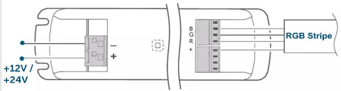
+12V / +24V - + B G R + RGB Stripe9
text_image
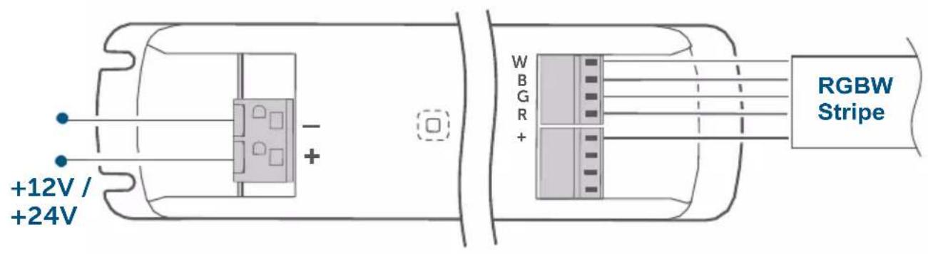
+12V / +24V RGBW Stripe W B G R + -10
text_image
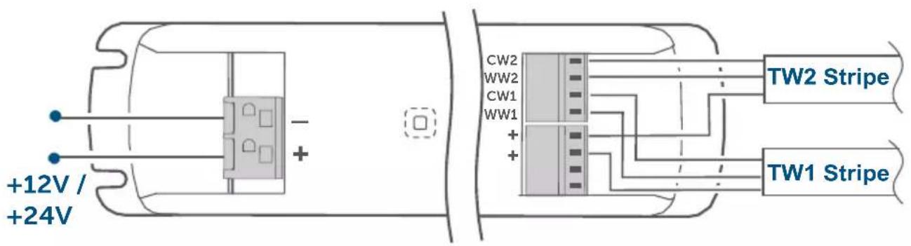
+12V / +24V CW2 WW2 CW1 WW1 + + TW2 Stripe TW1 Stripe11
text_image
HAP Homematic IP12
natural_image
Line drawing of a hand holding a pen with a green circular icon on the device (no text or symbols)Inhaltsverzeichnis
5.4.2 HCL (Human Centric Lightning)
1 Homematic IP LED Controller – RGBW
1 Operating manual
Documentation © 2022 eQ-3 AG, Germany
All rights reserved. Translation from the original version in German. This manual may not be reproduced in any format, either in whole or in part, nor may it be duplicated or edited by electronic, mechanical or chemical means, without the written consent of the publisher.
Typographical and printing errors cannot be excluded. However, the information contained in this manual is reviewed on a regular basis and any necessary corrections will be implemented in the next edition. We accept no liability for technical or typographical errors or the consequences thereof.
All trademarks and industrial property rights are acknowledged.
Printed in Hong Kong
Changes may be made without prior notice as a result of technical advances.
157662 (web)
Version 1.2 (09/2023)
Table of contents
1 Information about this manual 27
2 Hazard information 27
3 Function and device overview 28
4 General system information 29
5 Start-up 29
5.1 Installation instructions 29
5.2 Mounting and installation 30
5.3 Pairing 31
5.4 Basic settings 32
5.4.1 Colour Representation using the HSV Colour Space.....33
5.4.2 HCL (Human Centric Lighting) 33
5.4.3 Dim2Warm....33
6 Troubleshooting 34
6.1 Error codes and flashing sequences 34
6.2 Command not confirmed....34
6.3 Duty cycle 35
7 Restoring factory settings 35
8 Maintenance and cleaning.... 36
9 General information about radio operation....36
10 Technical specifications 36
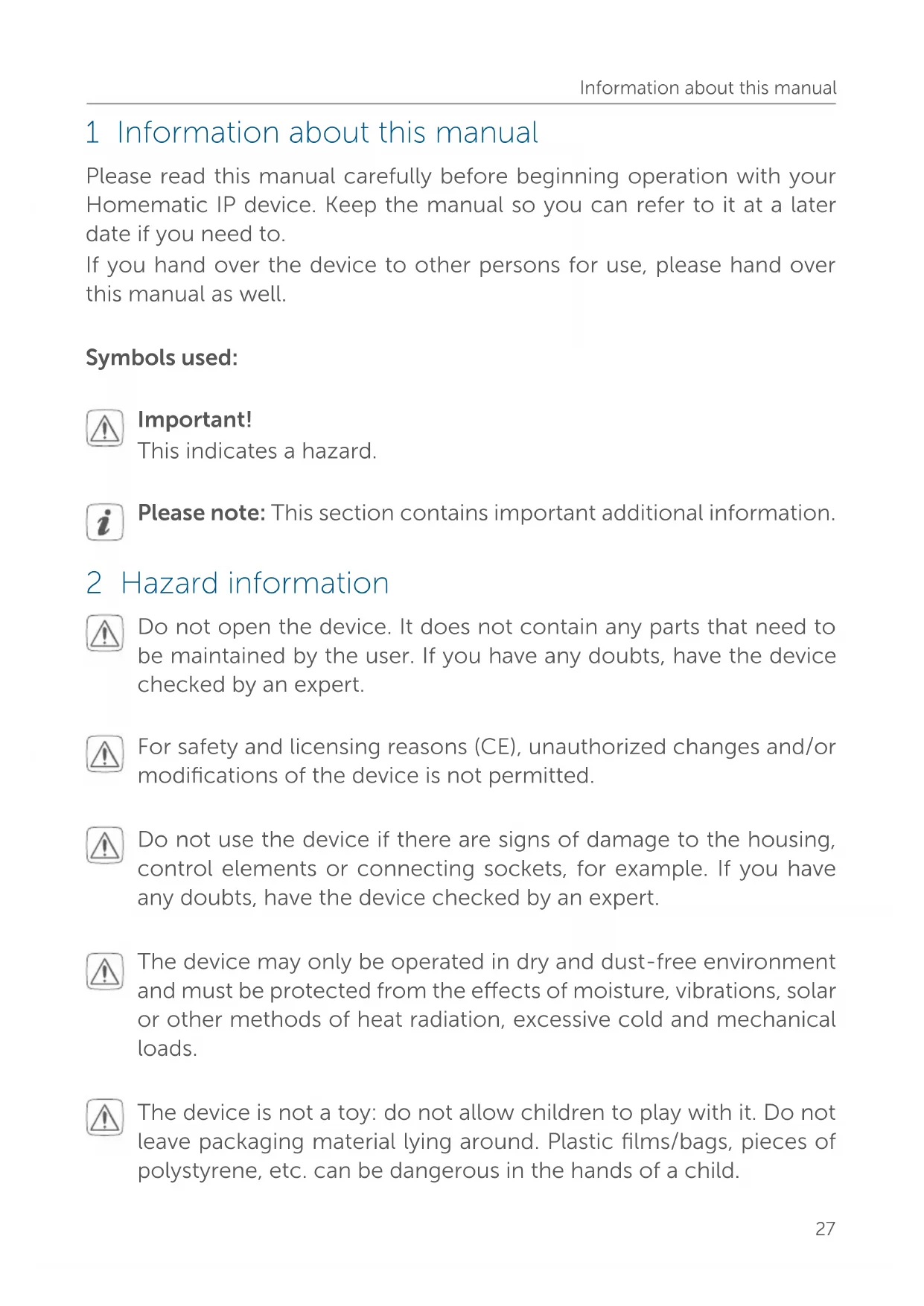
1 Information about this manual
Please read this manual carefully before beginning operation with your Homematic IP device. Keep the manual so you can refer to it at a later date if you need to.
If you hand over the device to other persons for use, please hand over this manual as well.
Symbols used:

Important!
This indicates a hazard.

Please note: This section contains important additional information.
2 Hazard information

Do not open the device. It does not contain any parts that need to be maintained by the user. If you have any doubts, have the device checked by an expert.

For safety and licensing reasons (CE), unauthorized changes and/or modifications of the device is not permitted.

Do not use the device if there are signs of damage to the housing, control elements or connecting sockets, for example. If you have any doubts, have the device checked by an expert.

The device may only be operated in dry and dust-free environment and must be protected from the effects of moisture, vibrations, solar or other methods of heat radiation, excessive cold and mechanical loads.

The device is not a toy: do not allow children to play with it. Do not leave packaging material lying around. Plastic films/bags, pieces of polystyrene, etc. can be dangerous in the hands of a child.

We accept no liability for damage to property or personal injury caused by improper use or the failure to observe the hazard warnings. In such cases, all warranty claims are void. We accept no liability for any consequential damage.

When connecting to the device terminals, take the permissible cables and cable cross sections into account.

Exceeding this capacity could lead to the destruction of the device, fires or electric shocks.

Please take the technical data (in particular the maximum permissible switching capacity of the load circuits and the type of load to be connected) into account before connecting a load. Do not exceed the capacity specified for the controller.

The device may only be operated within a domestic environment, in business and trade areas and in small enterprises.

Using the device for any purpose other than that described in this operating manual does not fall within the scope of intended use and will invalidate any warranty or liability.
3 Function and device overview
The Homematic IP LED Controller – RGBW enables simple control of RGBW LED lighting directly and wirelessly via the Homematic IP system. Colour, brightness and saturation can be controlled independently of each other.
The LED controller offers the option of controlling either one RGB(W) strip, two tunable white strips or up to four simple strips. Tunable white strips can be operated in Dim2Warm mode or dynamic daylight (HCL) mode.
Its robust housing makes the LED controller ideal for invisible mounting in partition walls or false ceilings.
In addition, easy remote control via app further increases ease of use. For
example, you can set customised initial brightness levels or automatic switch-offs after a configurable switch-on time.
All current technical documents and updates are provided at www.homematic-ip.com.
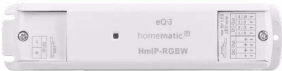
Device overview (figure 1):
(A) System button (pairing button and device LED)
(B) Mounting lugs
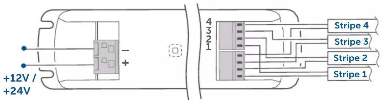
(C) Terminal with 2-pin input
(D) Terminal with 4-pin output
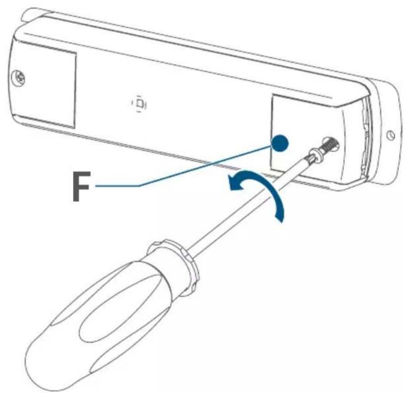
(E) Cap
(F) Cap
4 General system information
This device is part of the Homematic IP smart home system and works with the Homematic IP protocol. All devices in the Homematic IP system can be configured easily and individually with the CCU3 user interface or flexibly with the smartphone app in connection with the Homematic IP cloud. The functions provided by the system in combination with other components are described in the Homematic IP Wired User Guide, available for download. All current technical documents and updates are provided at www.homematic-ip.com.
5 Start-up
5.1 Installation instructions

Before installation, please note the device number (SGTIN) labelled on the device as well as the exact application purpose in order to facilitate later allocation. You can also find the device number on the QR code sticker supplied.

Incorrect installation also means that you risk serious damage to property, e.g. due to fire. You risk personal liability for personal injury and property damage.

Please observe the hazard information in section "2 Hazard information" auf Seite 27 during installation.

Please note the insulation stripping length of the conductor to be connected, indicated on the device.
Permitted cable cross-sections for connection to a supply voltage of 12–24 VDC are:
| Rigid cable [mm2] |
| 0.5–2.5 |
Permitted cable cross sections for connecting to the LED strips are:
| Rigid cable [mm2] |
| 0.2–1.5 |
5.2 Mounting and installation

Please read this entire section before starting to install the device.

Make sure there are no electricity cables or similar at the desired mounting location!

The device must only be used for fixed installations. The device must be securely attached within a fixed installation.
Proceed as follows to mount the LED controller in a false ceiling or partition wall:
- Position the LED controller at the desired location.
- Mark the drilling points using the openings of the mounting lugs (B).
- Select the appropriate screws and dowels.
- Drill the holes according to the screw size and insert the dowels.
- You can now mount the LED controller over the mounting brackets using the screws (fig. 2).
Proceed as follows to mount the LED controller in a partition wall or false ceiling:
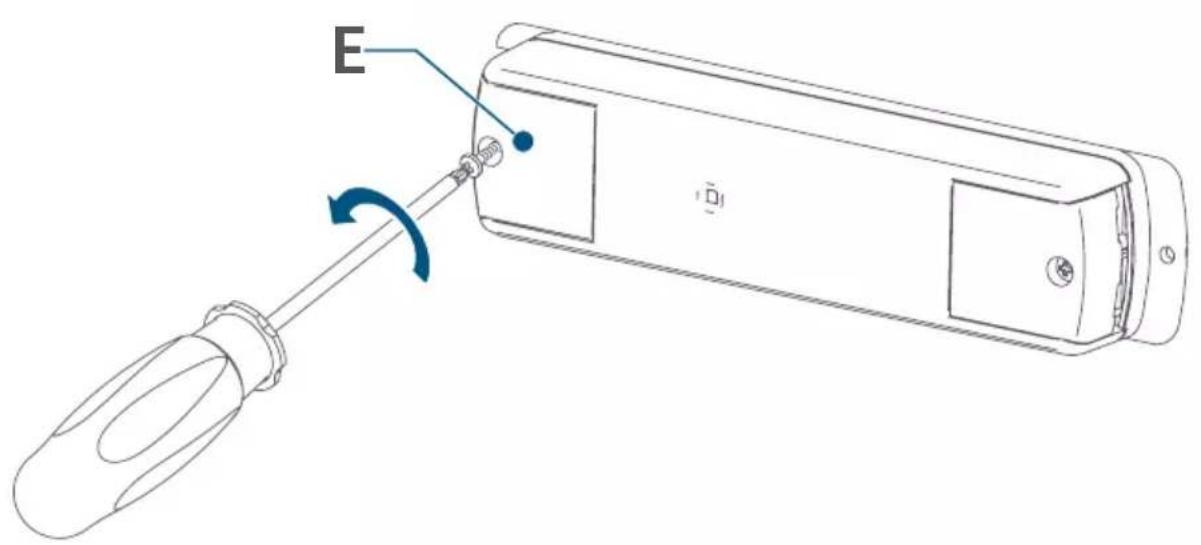
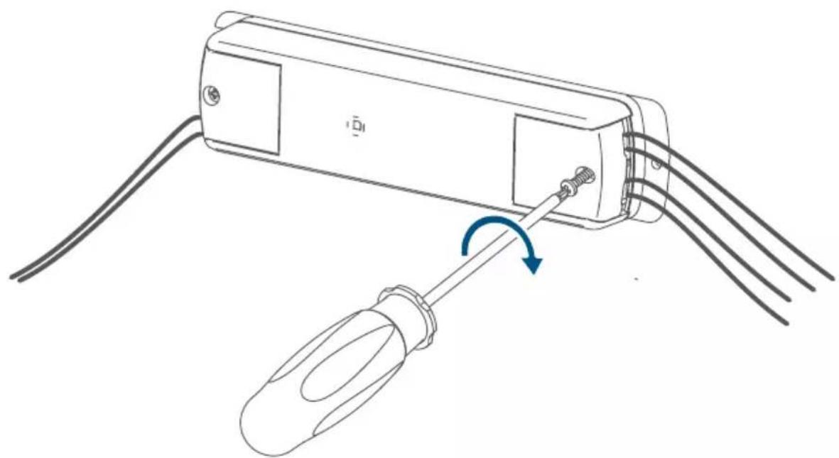
- Loosen the screw on the cap (E) using a screwdriver (fig. 3).
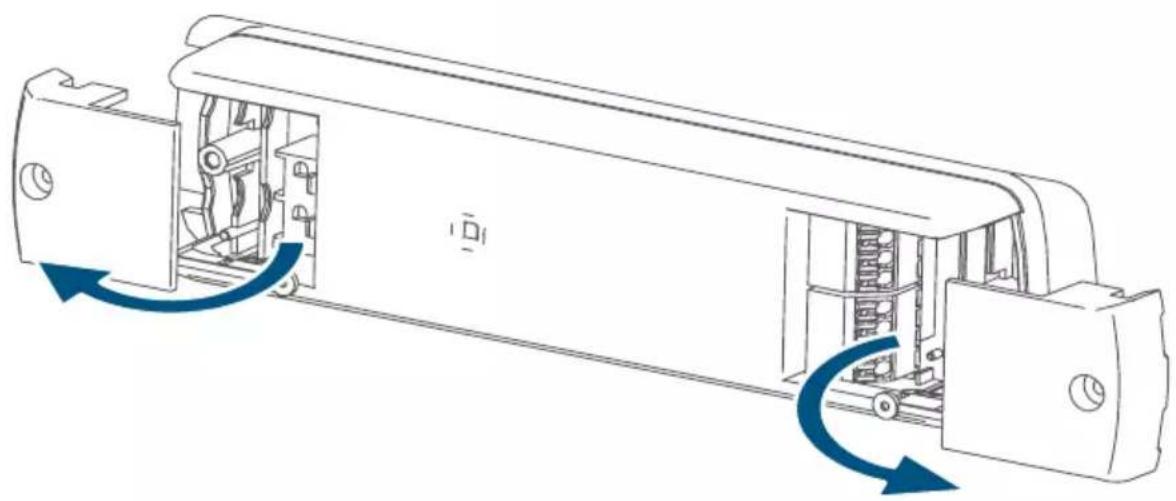
- Open the cap (fig. 5).
- Connect the power supply unit to the terminal (C) (2-pin input) according to the connection diagrams (fig. 6 to 10).

The power supply unit must be a converter with safety extra-low voltage (SELV) for LED modules in accordance with EN 61347-1, Annex L. The power supply unit must be short-circuit proof (conditional or unconditional) or fail-safe.
- Loosen the screw on the opposite cap (F) (fig. 4).
- Open the cap (fig. 5).
- Connect the loads to the terminal (D) (4-pin output) according to the connection diagrams (fig. 7 to 10).
- Close the LED controller caps again.
- Switch on the power supply to activate the device's pairing mode.
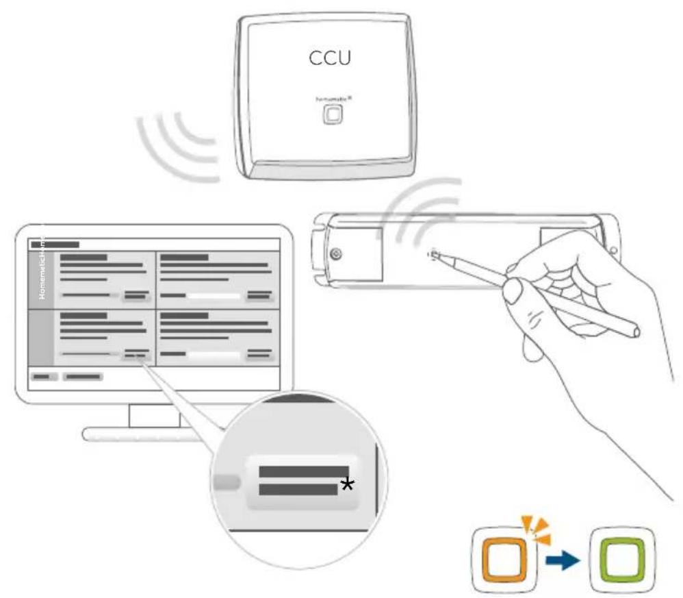
5.3 Pairing

Please read this entire section before starting the pairing procedure.

First set up your Homematic IP Access Point via the Homematic IP app to enable operation of other Homematic IP devices within your system. For further information, please refer to the Access Point operating manual.

You can pair the device with either the access point or the Homematic Central Control Unit CCU3. For detailed information, please refer to the Homematic IP User Guide, available for download in the download area of www.homematic-ip.com.
To integrate the device into your system and to enable control via the free Homematic IP app, you must first add the device to your Homematic IP Access Point.
To add the device, please proceed as follows:
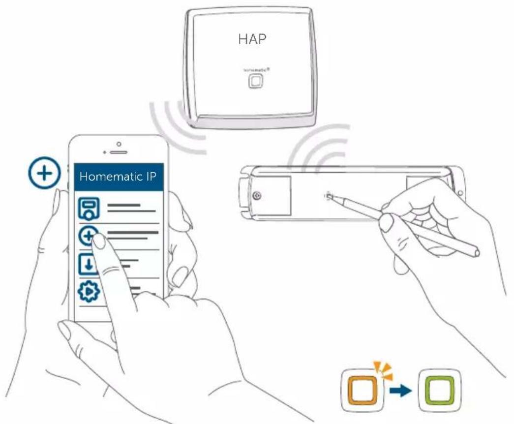
- Open the Homematic IP app on your smartphone.
- Select the menu item "Add device".
- When the power supply is switched on, the actuator's pairing mode is active for 3 minutes (fig. 11).

You can manually launch the pairing mode for another 3 minutes by briefly pressing the system button (A) (fig. 11).
- Your device will automatically appear in the Homematic IP app.
- To confirm, enter the last four digits of the device number (SG-TIN) in your app, or scan the QR code. The device number can be found on the sticker supplied or attached to the device.
- Wait until pairing is completed.
- If pairing was successful, the LED (A) lights up green. The device is now ready for use.
- If the LED lights up red, please try again.
- Select the desired solution for your device.
- In the app, give the device a name and allocate it to a room.
5.4 Basic settings
The operating mode of the LED controller is set in the device settings of the user interfaces (HmIP app and WebUI). This must be set according to the intended use. The following options are available:
- 4 x Single LED strips (fig. 7)
- 1 x RGB (fig. 8)
- 1 x RGBW (fig. 9)
- 2 x Tunable White (fig. 10)
5.4.1 Colour Representation using the HSV Colour Space
Using the HSV colour space, the starting colour is defined by use of an RGB(W) stripe. It is made up of the three terms Hue (H), Saturation (S) and Value (V). Hue H is defined as a circle (0—360°) in the course of which all colours occur. Saturation S specifies the intensity of the colour, where the starting colour increasingly moves towards white as the number reduces. Value V specifies the total brightness of the defined starting colour.
5.4.2 HCL (Human Centric Lighting)
Human Centric Lighting (HCL) describes the adaptation of the lighting in line with the natural course of daylight: in the morning, a warm colour temperature (reddish light) dominates, whereas over the course of the day towards noon the colour temperature rises (bluish light). Towards the evening, the colour temperature falls again. The artificial mimicry of the colour temperature progression can help to increase people's ability to concentrate.
5.4.3 Dim2Warm
The Dim2Warm mode simulates the dimming behaviour of a traditional incandescent lamp: if the lamp is lit very low, a very warm colour temperature is emitted, which can ensure a cosy and comfortable mood. As the brightness increases, the colour temperature is raised, with the result that at full brightness, cold and thus subjectively bright light is emitted.
6 Troubleshooting
6.1 Error codes and flashing sequences
| Flashing code Meaning Solution | ||
| Short orange flash-es | Radio transmission/attempting to transmit/data transmission | Wait until the transmission is completed. |
| 1x long green flash Tr | Transmission confirmed | You can continue operation. |
| Short orange flash-es (every 10 s) | Pairing mode active E | Enter the last four numbers of the device's serial number to confirm (see "5.3 Pairing" auf Seite 31). |
| 6x long red flashes D | Device defective Please | see your app for error message or contact your retailer. |
| 1x orange and 1x green flash | Test display | You can continue once the test display has stopped. |
| 1x long red flash Tran | smission failed or duty cycle limit reached | Please try again (see sec. "6.2 Command not confirmed" auf Seite 34 or "6.3 Duty cycle" auf Seite 35). |
6.2 Command not confirmed
If at least one receiver does not confirm a command, the device LED (A) lights up red at the end of the failed transmission process. The failed transmission may be caused by radio interference (see "9 General information about radio operation" auf Seite 36). This may be caused by the following:
- Receiver cannot be reached.
- Receiver is unable to execute the command (load failure, mechanical blockade, etc.).
- Receiver is faulty.
6.3 Duty cycle
The duty cycle is a legally regulated limit of the transmission time of devices in the 868 MHz range. The aim of this regulation is to safeguard the operation of all devices working in the 868 MHz range.
In the 868 MHz frequency range we use, the maximum transmission time of any device is 1% of an hour (i.e. 36 seconds in an hour). Devices must cease transmission when they reach the 1% limit until this time restriction ends. Homematic IP devices are designed and produced with 100% conformity to this regulation.
During normal operation, the duty cycle is not usually reached. However, repeated and radio-intensive pairing processes mean that it may be reached in isolated instances during start-up or initial installation of a system. If the duty cycle limit is exceeded, this is indicated by the LED (A) emitting a long red flash, and the device may temporarily not function. The device will start working correctly again after a short period (max. 1 hour).
7 Restoring factory settings

The device's factory settings can be restored. If you do this, you will lose all your settings.
To restore the factory settings of the device, please proceed as follows:
- Press and hold down the system button (A) for 4 seconds, until the LED (A) starts quickly flashing orange (fig. 13).
- Release the system button.
- Press and hold down the system button for 4 seconds again, until the LED lights up green (fig. 14).
- Release the system button again to conclude the procedure.
The device will perform a restart.
8 Maintenance and cleaning

The product does not require any maintenance. Leave any maintenance or repair to a specialist.
Clean the device using a soft, clean, dry and lint-free cloth. Do not use any detergents containing solvents, as they could corrode the plastic housing and label.
9 General information about radio operation
Radio transmission is performed on a non-exclusive transmission path, which means that there is a possibility of interference occurring. Interference can also be caused by switching operations, electrical motors or defective electrical devices.

The transmission range within buildings can differ significantly from that available in open space. Besides the transmitting power and the reception characteristics of the receiver, environmental factors such as humidity in the vicinity play an important role, as do on-site structural/screening conditions.
Hereby, eQ-3 AG, Maiburger Str. 29, 26789 Leer/Germany declares that the radio equipment type Homematic IP HmIP-RGBW is in compliance with Directive 2014/53/EU. The full text of the EU declaration of conformity is available at the following internet address: www.homematic-ip.com.
10 Technical specifications
Device short description: HmIP-RGBW
Supply voltage: 12-24 VDC
Current consumption: 8.5 A (max. 2.1 A per channel)
Power consumption
Standby: 60 mW @ 24 V
PWM base frequency: 1 kHz
Cable type and cross section:
(Rigid cable)
Input terminals 0.5–2 mm ^4
Output terminals 0.2–1.5 mm ^4
Cable length (input
and output terminals) < 3 m
External diameter
Input cables 7 mm
Output cables 5 mm
Protection rating: IP20
Ambient temperature: 5 to 40 °C
Dimensions (W x H x D): 170 x 40 x 26 mm
Weight: 79 g
Radio frequency band: 868.0-868.60 MHz
869.4-869.65 MHz
Max. radio transmission power 10 dBm
Receiver category: SRD category 2
Typical range in open space: 260 m
Duty cycle: < 1 % per h/< 10 % per h
Protection class: III
Pollution degree: 2
Subject to modifications.
| Load type | Channel 1-4 | |
| Resistive load | 2.1 A | |
| LED without ballast | 2.1 A/50.4 VA | |
Instructions for disposal

This symbol means that the device must not be disposed of as household waste, general waste, or in a yellow bin or a yellow sack.
For the protection of health and the environment, you must take the product and all electronic parts included in the scope of delivery to a municipal collection point for old electrical and electronic equipment to ensure their correct disposal. Distributors of electrical and electronic equipment must also take back obsolete equipment free of charge.
By disposing of it separately, you are making a valuable contribution to the reuse, recycling and other methods of recovery of old devices.
Please also remember that you, the end user, are responsible for deleting personal data on any old electrical and electronic equipment before disposing of it.
Information about conformity

The CE mark is a free trademark that is intended exclusively for the authorities and does not imply any assurance of properties.

For technical support, please contact your retailer.
Longueur du câble (bornes
Printed in Hong Kong
5.4.2 HCL (Human Centric Lightning)
5.4.2 HCL (Human Centric Lightning)
Printed in Hong Kong
5.4.2 HCL (Human Centric Lightning)
www.homematic-ip.com.
Apparaatcode: HmIP-RGBW
Stand-by: 60 mW @ 24 V
Free download of the Homematic IP app!

text_image
Blue QR code image, scannable for digital information retrieval
Download on the
App Store

text_image
Blue QR code image containing encoded data, no visible text or symbols beyond the matrix pattern
GET IT ON
Google Play
Bevollmächtigter des Herstellers: Manufacturer's authorised representative:
eQ-3 AG
Maiburger Straße 29
26789 Leer / GERMANY
www.eQ-3.de