HMIPW-DRI32 - Home Automation Homematic IP - Free user manual and instructions
Find the device manual for free HMIPW-DRI32 Homematic IP in PDF.

User questions about HMIPW-DRI32 Homematic IP
0 question about this device. Answer the ones you know or ask your own.
Ask a new question about this device
Download the instructions for your Home Automation in PDF format for free! Find your manual HMIPW-DRI32 - Homematic IP and take your electronic device back in hand. On this page are published all the documents necessary for the use of your device. HMIPW-DRI32 by Homematic IP.
USER MANUAL HMIPW-DRI32 Homematic IP
Installation instruction and operating manual
Wired Jalousieaktor - 4-fach S. 2
Wired Blind Actuator – 4 channels p. 33
text_image
homematic® eQ-3 24.0V Channel Select HmIPW-DRBL4 9 mmLieferumfang
Anzahl Bezeichnung
Printed in Hong Kong
natural_image
Technical line drawing of an electrical enclosure with multiple terminals and a central display (no text or symbols)3
text_image
L1 L2 L3 N M M M M4
natural_image
Line drawing of an electronic device with multiple ports and wiring (no text or symbols)5
natural_image
Line drawing of a hand inserting a component into an electrical control box (no text or symbols)6
natural_image
Line drawing of a hand inserting a power strip into an electrical enclosure (no text or symbols)7

natural_image
Line drawing of a hand holding a wall-mounted electrical circuit breaker (no text or symbols)Inhaltsverzeichnis
1 Homematic IP Wired Blind Actuator – 4 channels
1 Bus connection cable
1 Bus blind plug
1 Operating manual
Documentation © 2018 eQ-3 AG, Germany.
All rights reserved. Translation from the original version in German. This manual may not be reproduced in any format, either in whole or in part, nor may it be duplicated or edited by electronic, mechanical or chemical means, without the written consent of the publisher.
Typographical and printing errors cannot be excluded. However, the information contained in this manual is reviewed on a regular basis and any necessary corrections will be implemented in the next edition. We accept no liability for technical or typographical errors or the consequences thereof.
All trademarks and industrial property rights are acknowledged.
Printed in Hong Kong
Changes may be made without prior notice as a result of technical advances.
152433 (web)
Version 1.0 (02/2018)
Table of contents
1 Information about this manual....35
2 Hazard information....35
3 Function and device overview 39
4 General system information ....41
5 Start-up 42
5.1 Installation instructions 42
5.2 Selecting the supply voltage 44
5.3 Mounting and installation 44
5.4 Teaching-in....47
5.4.1 Connecting to the Homematic IP Central Control Unit CCU3 48
5.4.2 Connecting to the Homematic IP cloud via Wired Access Point....50
6 Operation....52
7 Error codes and flashing sequences....54
8 Restore factory settings....55
9 Maintenance and cleaning....56
10 Technical specifications....57
1 Information about this manual
Please read this manual carefully before beginning operation with your Homematic IP Wired component. Keep the manual so you can refer to it at a later date if you need to.
If you hand over the device to other persons for use, please hand over this manual as well.
Symbols used:

Attention!
This indicates a hazard.
Please note: This section contains important additional information.
2 Hazard information
Do not open the device. It does not contain any parts that can be maintained by the user. There is a risk of electric shock if the device is opened. If you have any doubts, have the device checked by an expert.
For safety and licensing reasons (CE), unauthorized change and/or modification of the device is not permitted.

Do not use the device if there are signs of damage to the housing, control elements or connecting sockets, for example. If you have any doubts, have the device checked by an expert.
The device may only be operated in dry and dust-free environment and must be protected from the effects of moisture, vibrations, solar or other methods of heat radiation, cold and mechanical loads.
The device is not a toy; do not allow children to play with it. Do not leave packaging material lying around. Plastic films/bags, pieces of polystyrene, etc. can be dangerous in the hands of a child.
We do not assume any liability for damage to property or personal injury caused by improper use or the failure to observe the hazard information. In such cases, any claim under warranty is extinguished! For consequential damages, we assume no liability!
The actuator is part of the building installation. The relevant national standards and directives must be taken into consideration during planning and set-up. The device has been designed solely for operation on a 230 V/50 Hz AC supply. Only
qualified electricians (to VDE 0100) are permitted to carry out work on the 230 V mains. Applicable accident prevention regulations must be complied with whilst such work is being carried out. To avoid electric shocks from the device, please disconnect the mains voltage (trip the miniature circuit-breaker). Non-compliance with the installation instructions can cause fire or introduce other hazards.
Mains supply and SELV/PELV power circuits may not be connected together (in combination) to the different switching outputs.

When connecting to the device terminals, take the permissible cables and cable cross sections into account.
Connected loads require sufficient insulation.
Exceeding this capacity could lead to the destruction of the device, fires or electric shocks.

Please take the technical data (in particular the maximum permissible switching capacity of the load circuits and the type of load to be connected) into account before connecting a load. Do not exceed the capacity specified for the device.
The load current circuits have to be secured by a cable protection switch in accordance with EN60898-1 (tripping characteristic B or C, max. 10 A rated current, min. 6 kA interrupting rating, energy limiting class 3).

For secure operation, the device has to be installed in a power distribution panel according to VDE 0603, DIN 43871 (low-voltage sub-distribution board), DIN 18015-x. The installation must be carried out on a mounting rail (DIN rail) according to EN 60715. Installation and wiring have to be performed according to VDE 0100 (VDE 0100-410, VDE 0100-510 etc.). Please consider the technical connection requirements (TAB) of your energy supplier.
Before installation and connection of the device, mains voltage must be disconnected and live parts in the surrounding must be covered.
The device has not been designed to support safety disconnection.
Only shutters and blinds with limit switches (mechanical or electronic) should be used. Before putting the actuator into operation, check that the limit switches on the connected motors have been adjusted correctly.

Do not connect three-phase motors.

If you use the device/system in a security application it has to be operated in connection with an UPS (uninterruptible power supply) in order to bridge possible power failure.

The device may only be operated within domestic environment, in business and trade areas as well as in small enterprises.

Using the device for any purpose other than that described in this operating manual does not fall within the scope of intended use and shall invalidate any warranty or liability.
3 Function and device overview
The Homematic IP Wired Blind Actuator – 4 channels can be easily installed on a DIN rail within a distribution board. Once installed, the device controls connected blinds, shutters and awnings via four channels.
The blind actuator offers comfortable control of connected blind, shutter and awning drives via connected push-buttons, remote controls or the free Homematic IP app.
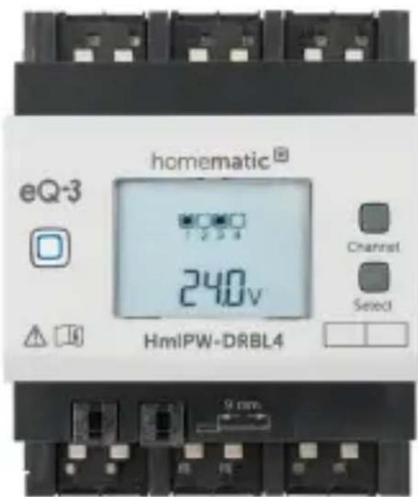
Device overview (see figure 1):
(A) System button (teach-in/pairing button and LED)
(B) Channel button
(C) Select button
(D) LC display
(E) Bus connection 1
(F) Bus connection 2
(G) Connecting terminals for phase conductor
(H) Connecting terminals for switched phase conductor for moving the motor up
(I) Connecting terminals for switched phase conductor for moving the motor down
Display overview (see figure 1):
| Symbol Meaning | |
 | Channel switched on |
 1 1 | Channel switched off |
 | Data is received by the bus |
 | Data is sent to the bus |
 | Blind or shutter level of the selected channel |
 | Slat position of blind at selected channel |
 | Percent value (switched on, if the height or slats position is displayed) |
 | Temperature indication (switched on, if temperature is displayed) |
 | Voltage indication (switched on, if voltage is displayed) |
4 General system information
This device is part of the Homematic IP smart home system and works with the Homematic IP protocol. All devices of the system can be configured comfortably and individually with the user interface of the Central Control Unit CCU3 or flexibly via the Homematic IP smartphone app in connection with the Homematic IP cloud. All available functions provided by the system in combination with other components are described in the Homematic IP Wired Installation Guide. All current technical documents and updates are provided at www.eQ-3.com.
5 Start-up
5.1 Installation instructions

Before installing and setting up the device you have put into operation a Homematic IP Wired Access Point (HmIPW-DRAP) first.

Before installation, please note the device number (SGTIN) labelled on the device as well as the exact application purpose in order to make later allocation easier. You can also find the device number on the QR code sticker supplied.
Please note! Only to be installed by persons with the relevant electro-technical knowledge and experience!*
Incorrect installation can put
- your own life at risk;
• and the lives of other users of the electrical system.
Incorrect installation also means that you are running the risk of serious damage to property, e.g. because of a fire. You may be personally liable in the event of injuries or damage to property.
Contact an electrical installer!
\*Specialist knowledge required for installation:
The following specialist knowledge is particularly important during installation:
- The "5 safety rules" to be used: Disconnect from mains; Safeguard from switching on again; Check that system is de-energised; Earth and short circuit; Cover or cordon off neighbouring live parts;
- Select suitable tool, measuring equipment and, if necessary, personal safety equipment;
- Evaluation of measuring results;
- Selection of electrical installation material for safeguarding shut-off conditions;
• IP protection types;
• Installation of electrical installation material; - Type of supply network (TN system, IT system, TT system) and the resulting connecting conditions (classical zero balancing, protective earthing, required additional measures etc.).
Please observe the hazard information in section "2 Hazard information" on page 35 during installation.
Please note the insulation stripping length of the conductor to be connected, indicated on the device.
Permitted cable cross sections for connecting to the blind actuator are:
| rigid cable [mm2] flexible cable without ferrule [mm2] |
| 0.75 – 2.50 0.75 – 2.50 |
5.2 Selecting the supply voltage
Voltage supply of the blind actuator is established only via the Homematic IP Wired bus. The bus is supplied by the Homematic IP Wired Access Point (HmIPW-DRAP) (please refer to the user manual of the HmIPW-DRAP).
The maximum total current consumption of the blind actuator is as follows:
$$ I _ {\mathrm{ges}} = 1 0 0 \mathrm{mA} $$
5.3 Mounting and installation
Please read this entire section before starting to install the device.
To install the blind actuator on a DIN rail within a distribution board, please proceed as follows:
- Disconnect the power distribution panel and cover any live parts, if required (see hazard information).
-
Remove the cover of the power distribution panel.
-
Place the blind actuator onto the DIN rail (see figure 2). Make sure that you can read the letters on the device and display and that the connecting terminals of channel 1 and 2 are at the top.
- Make sure that the catch spring engages properly and that the device is securely seated on the rail.
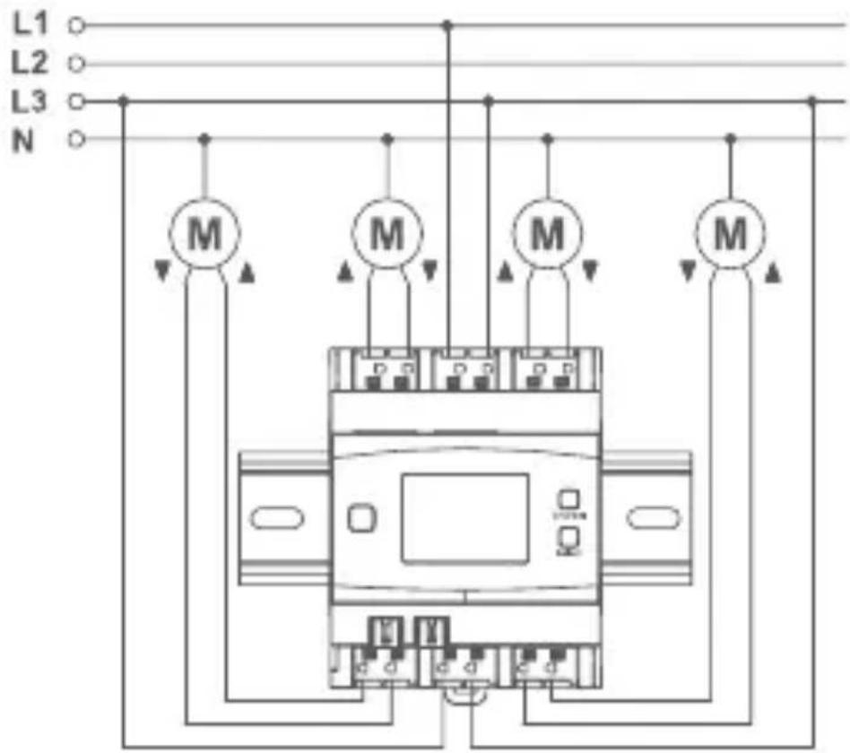
- Wire the device according to the connecting diagram in figure 3.
- Connect the phase conductor for the selected channel to the corresponding terminal (G) (see figure 3). Any types of phase conductors (L1, L2, L3) can be connected to the power input terminals.
- Connect the switched phase conductor to move up the motor for the selected channel to the corresponding terminal (▲) (H) (see figure 3).
- Connect the switched phase conductor to move down the motor for the selected channel to the corresponding terminal (▼) (I) (see figure 3).
The phase conductor connection is marked with an arrow pointing to the centre of the device, the switched phase conductor with an arrow pointing towards outside. To connect or loosen the conductor, the white actuation lever at the top of the clamp has to be pressed.
The network terminals may be used only for connecting the power supply to the device or for connecting loads to the device. The connection (looping through) of conductors via the network terminals of the device to other devices is not permitted!
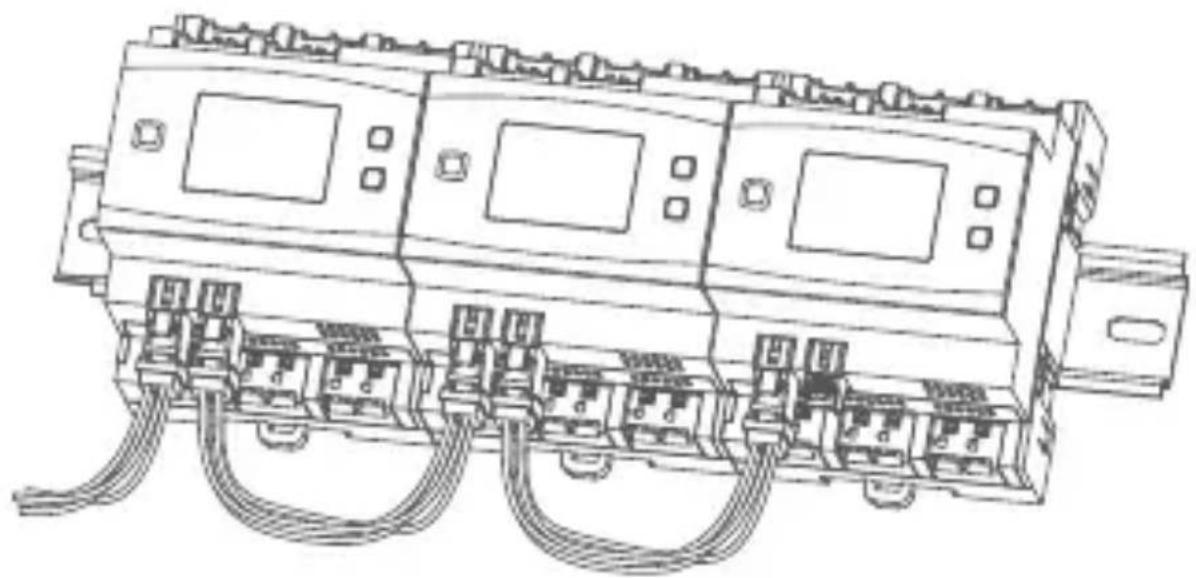
- Connect the bus using the supplied connecting cable (see figure 4).
For electrical safety reasons, only the supplied Homematic IP Wired Bus Cable may be used for connecting the device to the Homematic IP Wired bus. Furthermore, an eQ-3 Homematic IP Wired Bus Cable with other lengths (available as accessory) can be used.

The bus connections (E) and (F) are switched in parallel. However, the incoming or outgoing bus cable can be connected to any of the two connections.
- Use the supplied bus blind plug, if bus connection 1 (E) or bus connection 2 (F) are not needed.
- Reattach the cover of the power distribution panel.
- Switch the fuse of the power circuit on again to activate the teach-in mode of the device (see „5.4 Teaching-in“ on page 47).
After installation and before connecting the device to the app, simple operating functions (e.g. for test purposes) are available directly on the device (see "6 Operation" on page 52).
5.4 Teaching-in

Please read this entire section before starting the teach-in procedure.

First, set up your Homematic IP Wired Access Point to enable operation of other Homematic IP Wired devices within your system. For further information, please refer to the operating manual of the Wired Access Point.
To integrate the blind actuator into your system and enable it to communicate with other Homematic IP Wired devices, you must teach it in first.
You can connect the blind actuator to the Central Control Unit CCU3 for local configuration via PC.
As an alternative, connect the device to the Homematic IP cloud for flexible control via smartphone app.
You can
- control the wired system via smartphone app using the Homematic IP Wired Access Point (HmIPW-DRAP) or
- combine wired devices with wireless
Homematic IP devices via the Homematic IP Access Point (HmIP-HAP).
5.4.1 Connecting to the Homematic IP Central Control Unit CCU3
After connecting the Homematic IP Wired device to the WebUI, it can be conveniently controlled, configured and be used in central control unit programs via the software interface. To connect the blind actuator to the Central Control Unit CCU3, proceed as follows:
- Set up your Central Control Unit CCU3 as described in the operating manual and connect the Homematic IP Wired Access Point.
- Start the user interface "Homematic WebUI" on your computer.
- Click the "Teach-in devices" button on the right-hand side of the screen.

text_image
Adress Home page Browse messages (31) Service messages (32) Search to devices Help Name: Date: Email: Email: Received: Received: 11.8 Used: Enter school Enter school 30 password set unchatell unchatell- To activate teach-in mode, click "Teach-in HmIP device" in the next window. The teach-in mode of the Central Control Unit will be activated for 60 seconds. An information box shows how
much teach-in time remains.
text_image
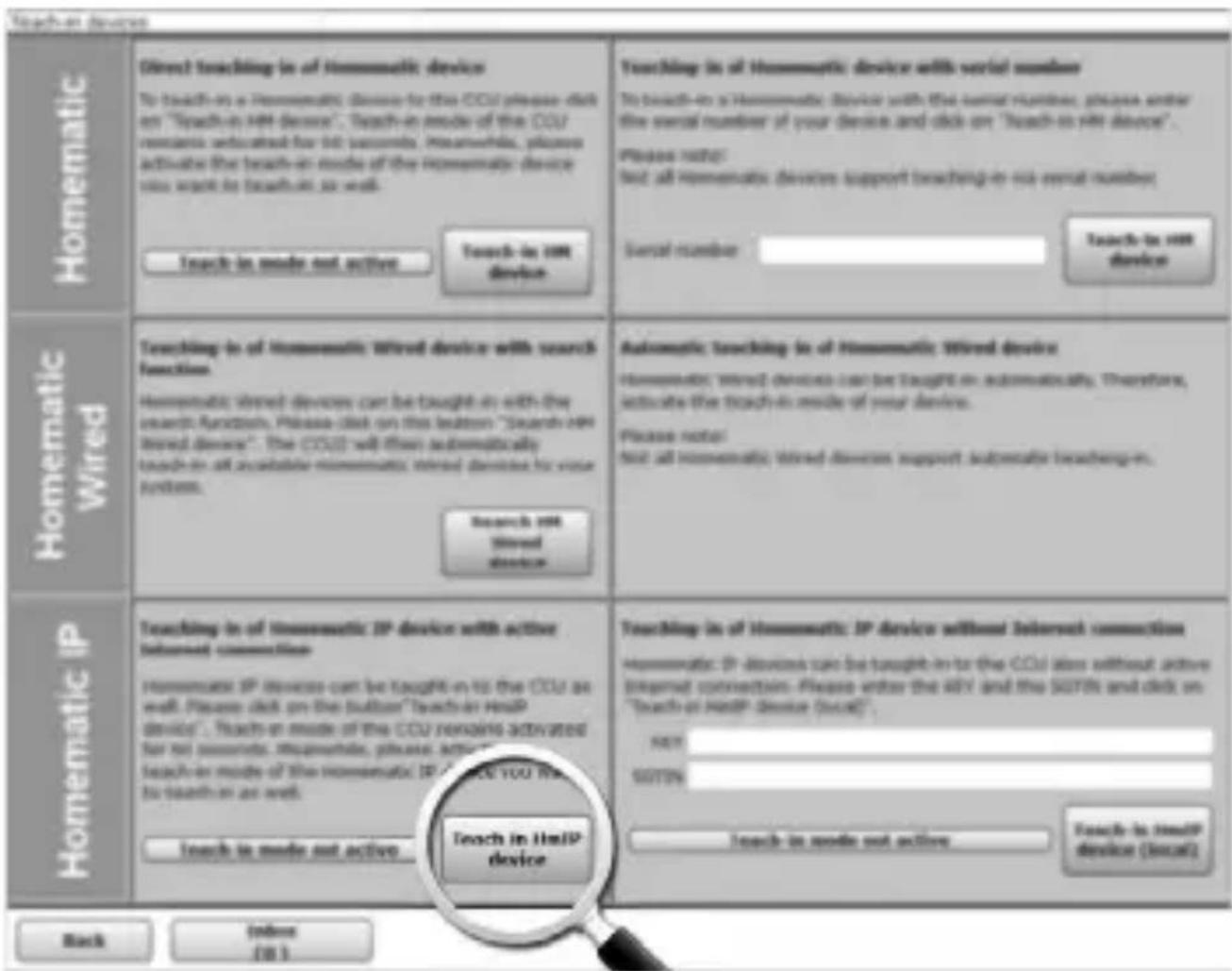
Homematic Direct touching in of Homematic device To touch-in a Homematic device for this CCU please click on "Search-in HH device". Teach-in mode of the CCU remains educated for 10 seconds. Meanwhile, please activate the touch-in mode of the Homematic device you want to touch-in so well. Touch-in mode not active Touch-in HH device Touching in of Homematic wired device with search function. Homematic wired devices can be taught in with the search function. Please click on this button "Search in HH wired device". The CCU will then automatically touch-in all accessible Homematic wired devices for your system. Search in HH Mixed device Automatic touching in of Homematic Wired device Homematic wired devices can be taught in automatically. Therefore, activate the touch-in mode of your device. Please note: Not all homematic wired devices support automatic telechings. Homematic IP Touching in of Homematic IP device with active Internet connection Homematic IP devices can be taught in to the CCU as well. Please click on the button "Search-in HHP device". Teach-in mode of the CCU remaining activated for all seconds. Meanwhile, please activate the touch-in mode of the Homematic IP to touch-in as well. Touch-in mode not active Touch in HHP device Touching in of Homematic IP device without Internet connection Homematic IP devices can be taught in to the CCU also without active Internet connection. Please enter the QQY and the SOTIN and click on "Search-in HHIP device (local)". NEXT SOTIN Touch-in mode not active Touch-in mode not active Touch-in wire device (local) Back Index (18)- After connecting to the bus line, the teach-in mode of the blind actuator remains activated for 3 minutes. If the 3 minutes have not yet expired, the device will be connected automatically.

You can manually start the teach-in mode for another 3 minutes by pressing the system button (A) briefly (see figure 5).
• After a short time, the newly connected device appears in the inbox of your software interface.
Newly connected devices and the corresponding channels are ready for operation and configuration only after they have been configured in the inbox. You will find further information in the Homematic IP Wired Installation Guide, available for download at www.eQ-3.com.

For operation without Internet connection, please select the option "Teaching-in of Homematic IP device without Internet connection". Please enter the SGTIN and key of the device into the corresponding fields. You will find the SGTIN and the key on the supplied sticker. Please keep the sticker in safe place.
5.4.2 Connecting to the Homematic IP cloud via Wired Access Point
If you want to control your Homematic IP Wired devices flexibly via smartphone app, they can be connected to the Homematic IP cloud. To do this, please proceed as follows:
- Open the Homematic IP app on your smartphone.
- Connect the Homematic IP Wired Access Point via the smartphone app to the Homematic IP cloud, as described in the corresponding user manual
- Select the menu item "Teach-in device".
• After connecting to the bus line, the teach-in
mode of the blind actuator remains activated for 3 minutes.

You can manually start the teach-in mode for another 3 minutes by pressing the system button (A) briefly (see figure 5).
- Your device will automatically appear in the Homematic IP app.
- To confirm, please enter the last four digits of the device number (SGTIN) in your app or scan the QR code. Therefore, please see the sticker supplied or attached to the device.
- Please wait until teach-in is completed.
- If connecting was successful, the LED (A) lights up green. The device is now ready for use.
- If the LED lights up red, please try again.
- Select the desired solution for your device.
- In the app, give the device a name and allocate it to a room.

If you are already using Homematic IP devices in your smart home system or if you want to combine your Homematic IP Wired devices with wireless Homematic IP components, you can also connect the Homematic IP Wired devices to an (installed) Access Point. Therefore, connect the Homematic IP Wired Access Point to the
(installed) Homematic IP Access Point, as described in the operating. Afterwards, please proceed as described above to connect the blind actuator.
6 Operation
Via the following push-buttons, simple operating functions are available directly on the device:
- system button (A)
- channel button (B)
- select button (C)
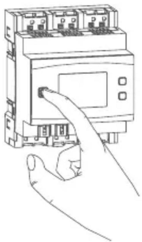
System button
By pressing the system button briefly (see figure 5), you can activate the LCD background lighting of all devices connected to the bus.
Channel button
By pressing the channel button briefly (see figure 6), you can select the desired channel. On each button press, you can switch to the next channel.
The selected channel is indicated by the flashing symbol. The current height (☐) and slats positions (☐) of the selected channel are shown in the display (alternating).
After switching on the blind actuator, the blinds/shutters/awnings are in an unknown position. The current height and slats position of a channel until reaching a limit switch cannot be displayed. During this time, the current moving direction will be displayed:
| Symbol Meaning | |
| --- | Move down |
| --- | Moved up |
| --- | Stop |
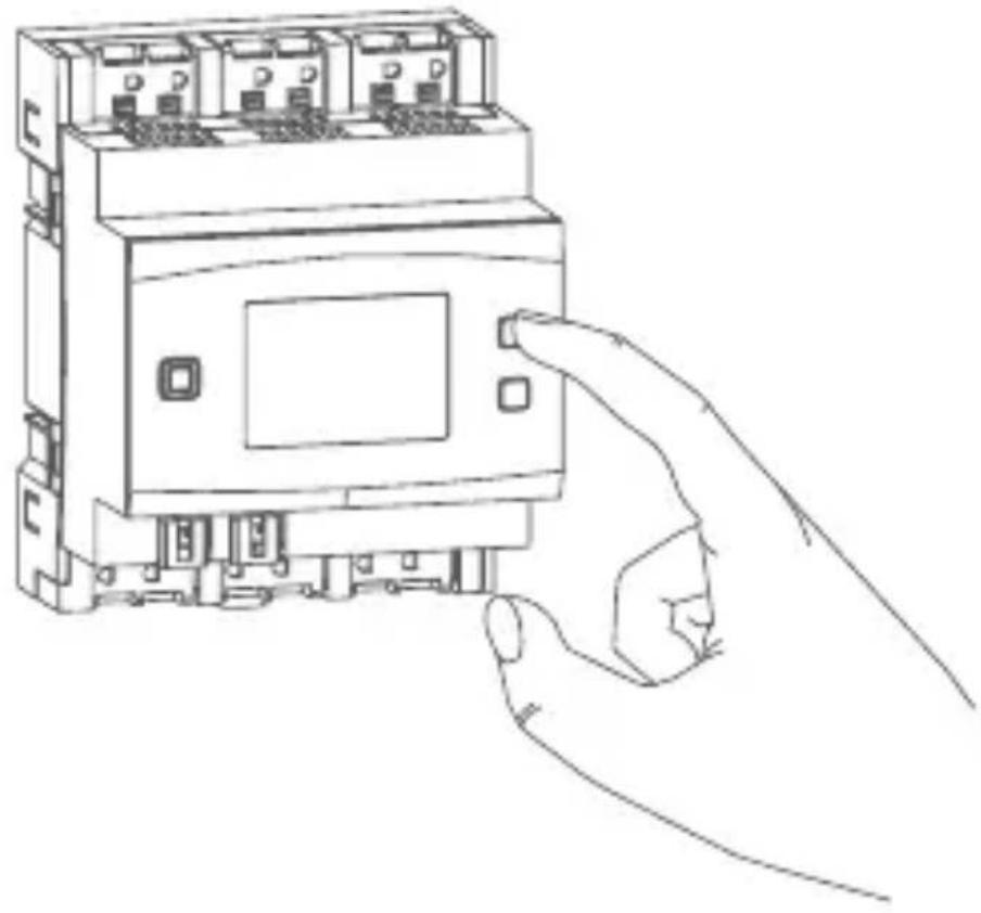
Select button
After selecting a channel via the channel button (see Channel button), you can select the channel condition by briefly pressing the select button (see figure 7) (move down - stop - move up - stop etc.). On each button press, you can switch to the next condition.
If you have not selected a channel, you can select the following options in the LC display by pressing the Select button briefly:
- bus supply voltage (in V)
• temperature in blind actuator (in °C) - empty display
7 Error codes and flashing sequences
| Flashing code / LC display | Meaning Solution | |
| Short orange flashing (every 10 s) | Teach-in mode active | Please enter the last four numbers of the device serial number to confirm (see „5.4 Teaching-in“ on page 47). |
| 6x long red flashing | Device defective | Please see your app for error message or contact your retailer. |
| 1x orange and 1 x green lighting | Test display Once | ce the test display has stopped, you can continue. |
| E10 Temperature | too high | Reduce the connected load and let the device cool down. |
| E11 Under-voltage | (bus voltage too low) | Check the voltage supply and adjust the voltage supply in accordance with the number of devices connected. |
8 Restore factory settings
The factory settings of the device can be restored. If you do this, you will lose all your settings.
To restore the factory settings of the blind actuator, please proceed as follows:
- Press and hold down the system button (A) for 4 seconds until the LED (A) quickly starts flashing orange (see figure 5).
- Release the system button again.
- Press and hold down the system button again for 4 seconds, until the LED lights up green.
- Release the system button to finish the procedure.
The device will perform a restart.
9 Maintenance and cleaning
The product does not require any maintenance. Enlist the help of an expert to carry out any maintenance or repairs.
The mains voltage must be disconnected before the device is removed (trip the miniature circuit-breaker). Only qualified electricians (to VDE 0100) are permitted to carry out work on the 230 V mains.
Clean the device using a soft, lint-free cloth that is clean and dry. Do not use any detergents containing solvents, as they could corrode the plastic housing and label.
10 Technical specifications
Device short description: HmIPW-DRBL4
Supply voltage: 24 VDC, +-5 %, SELV
Current consumption: 100 mA max./2.5 mA
(typically)
Standby power
consumption: 60 mW
Load type: motor load
Relay: changeover contact,

μ contact
Switching voltage: 230 V\~
Current carrying capacity
(channel): 2.2 A
Power loss of the device
for thermal calculation: 2.8 W max.
Cable type and cross
section: rigid and flexible cable,
0.75-2.5 mm²
Installation: mounting rail (DIN rail)
according to EN 60715
Degree of protection: IP20
Ambient temperature: -5 to +40 °C
Dimensions (W x H x D): 72 x 90 x 69 mm
(4 WM width)
Weight: 230 g
Subject to technical changes.
Instructions for disposal
Do not dispose of the device with regular domestic waste! Electronic equipment must be disposed of at local collection points for waste electronic equipment in compliance with the Waste Electrical and Electronic Equipment Directive.
Information about conformity

The CE sign is a free trading sign addressed exclusively to the authorities and does not include any warranty of any properties.

For technical support, please contact your retailer.
Free download of the Homematic IP app!

text_image
QR code image containing encoded data, no visible human-readable text

text_image
QR code image containing encoded data, no visible human-readable text
text_image
ANDROID APPON Google playBevollmächtigter des Herstellers: Manufacturer's authorised representative:

eQ-3 AG
Maiburger Straße 29 26789 Leer / GERMANY
www.eQ-3.de